US20180098673A1 - Glotite disinfecting wips dispencer/container - Google Patents
Glotite disinfecting wips dispencer/container Download PDFInfo
- Publication number
- US20180098673A1 US20180098673A1 US15/288,082 US201615288082A US2018098673A1 US 20180098673 A1 US20180098673 A1 US 20180098673A1 US 201615288082 A US201615288082 A US 201615288082A US 2018098673 A1 US2018098673 A1 US 2018098673A1
- Authority
- US
- United States
- Prior art keywords
- container
- dispenser
- glotite
- wipes
- cover
- Prior art date
- Legal status (The legal status is an assumption and is not a legal conclusion. Google has not performed a legal analysis and makes no representation as to the accuracy of the status listed.)
- Abandoned
Links
Images


Classifications
-
- A—HUMAN NECESSITIES
- A47—FURNITURE; DOMESTIC ARTICLES OR APPLIANCES; COFFEE MILLS; SPICE MILLS; SUCTION CLEANERS IN GENERAL
- A47K—SANITARY EQUIPMENT NOT OTHERWISE PROVIDED FOR; TOILET ACCESSORIES
- A47K10/00—Body-drying implements; Toilet paper; Holders therefor
- A47K10/24—Towel dispensers, e.g. for piled-up or folded textile towels; Toilet paper dispensers; Dispensers for piled-up or folded textile towels provided or not with devices for taking-up soiled towels as far as not mechanically driven
- A47K10/32—Dispensers for paper towels or toilet paper
- A47K10/34—Dispensers for paper towels or toilet paper dispensing from a web, e.g. with mechanical dispensing means
- A47K10/38—Dispensers for paper towels or toilet paper dispensing from a web, e.g. with mechanical dispensing means the web being rolled up with or without tearing edge
-
- A—HUMAN NECESSITIES
- A47—FURNITURE; DOMESTIC ARTICLES OR APPLIANCES; COFFEE MILLS; SPICE MILLS; SUCTION CLEANERS IN GENERAL
- A47K—SANITARY EQUIPMENT NOT OTHERWISE PROVIDED FOR; TOILET ACCESSORIES
- A47K10/00—Body-drying implements; Toilet paper; Holders therefor
- A47K10/24—Towel dispensers, e.g. for piled-up or folded textile towels; Toilet paper dispensers; Dispensers for piled-up or folded textile towels provided or not with devices for taking-up soiled towels as far as not mechanically driven
- A47K10/32—Dispensers for paper towels or toilet paper
- A47K10/46—Dispensers for paper towels or toilet paper with means for storing soiled towels
-
- B—PERFORMING OPERATIONS; TRANSPORTING
- B65—CONVEYING; PACKING; STORING; HANDLING THIN OR FILAMENTARY MATERIAL
- B65D—CONTAINERS FOR STORAGE OR TRANSPORT OF ARTICLES OR MATERIALS, e.g. BAGS, BARRELS, BOTTLES, BOXES, CANS, CARTONS, CRATES, DRUMS, JARS, TANKS, HOPPERS, FORWARDING CONTAINERS; ACCESSORIES, CLOSURES, OR FITTINGS THEREFOR; PACKAGING ELEMENTS; PACKAGES
- B65D11/00—Containers having bodies formed by interconnecting or uniting two or more rigid, or substantially rigid, components made wholly or mainly of plastics material
- B65D11/10—Containers having bodies formed by interconnecting or uniting two or more rigid, or substantially rigid, components made wholly or mainly of plastics material of polygonal cross-section and all parts being permanently connected to each other
-
- B—PERFORMING OPERATIONS; TRANSPORTING
- B65—CONVEYING; PACKING; STORING; HANDLING THIN OR FILAMENTARY MATERIAL
- B65D—CONTAINERS FOR STORAGE OR TRANSPORT OF ARTICLES OR MATERIALS, e.g. BAGS, BARRELS, BOTTLES, BOXES, CANS, CARTONS, CRATES, DRUMS, JARS, TANKS, HOPPERS, FORWARDING CONTAINERS; ACCESSORIES, CLOSURES, OR FITTINGS THEREFOR; PACKAGING ELEMENTS; PACKAGES
- B65D43/00—Lids or covers for rigid or semi-rigid containers
- B65D43/14—Non-removable lids or covers
- B65D43/16—Non-removable lids or covers hinged for upward or downward movement
- B65D43/163—Non-removable lids or covers hinged for upward or downward movement the container and the lid being made separately
- B65D43/169—Non-removable lids or covers hinged for upward or downward movement the container and the lid being made separately the lid, the hinge and the element connecting them to the container being made of one piece
-
- B—PERFORMING OPERATIONS; TRANSPORTING
- B65—CONVEYING; PACKING; STORING; HANDLING THIN OR FILAMENTARY MATERIAL
- B65D—CONTAINERS FOR STORAGE OR TRANSPORT OF ARTICLES OR MATERIALS, e.g. BAGS, BARRELS, BOTTLES, BOXES, CANS, CARTONS, CRATES, DRUMS, JARS, TANKS, HOPPERS, FORWARDING CONTAINERS; ACCESSORIES, CLOSURES, OR FITTINGS THEREFOR; PACKAGING ELEMENTS; PACKAGES
- B65D83/00—Containers or packages with special means for dispensing contents
- B65D83/08—Containers or packages with special means for dispensing contents for dispensing thin flat articles in succession
- B65D83/0805—Containers or packages with special means for dispensing contents for dispensing thin flat articles in succession through an aperture in a wall
- B65D83/0811—Containers or packages with special means for dispensing contents for dispensing thin flat articles in succession through an aperture in a wall with means for assisting dispensing
- B65D83/0841—Containers or packages with special means for dispensing contents for dispensing thin flat articles in succession through an aperture in a wall with means for assisting dispensing and for cutting interconnected articles
-
- B—PERFORMING OPERATIONS; TRANSPORTING
- B65—CONVEYING; PACKING; STORING; HANDLING THIN OR FILAMENTARY MATERIAL
- B65D—CONTAINERS FOR STORAGE OR TRANSPORT OF ARTICLES OR MATERIALS, e.g. BAGS, BARRELS, BOTTLES, BOXES, CANS, CARTONS, CRATES, DRUMS, JARS, TANKS, HOPPERS, FORWARDING CONTAINERS; ACCESSORIES, CLOSURES, OR FITTINGS THEREFOR; PACKAGING ELEMENTS; PACKAGES
- B65D83/00—Containers or packages with special means for dispensing contents
- B65D83/08—Containers or packages with special means for dispensing contents for dispensing thin flat articles in succession
- B65D83/0847—Containers or packages with special means for dispensing contents for dispensing thin flat articles in succession through an aperture at the junction of two walls
-
- B—PERFORMING OPERATIONS; TRANSPORTING
- B65—CONVEYING; PACKING; STORING; HANDLING THIN OR FILAMENTARY MATERIAL
- B65D—CONTAINERS FOR STORAGE OR TRANSPORT OF ARTICLES OR MATERIALS, e.g. BAGS, BARRELS, BOTTLES, BOXES, CANS, CARTONS, CRATES, DRUMS, JARS, TANKS, HOPPERS, FORWARDING CONTAINERS; ACCESSORIES, CLOSURES, OR FITTINGS THEREFOR; PACKAGING ELEMENTS; PACKAGES
- B65D83/00—Containers or packages with special means for dispensing contents
- B65D83/08—Containers or packages with special means for dispensing contents for dispensing thin flat articles in succession
- B65D83/0888—Containers or packages with special means for dispensing contents for dispensing thin flat articles in succession with provision for used articles
-
- A—HUMAN NECESSITIES
- A47—FURNITURE; DOMESTIC ARTICLES OR APPLIANCES; COFFEE MILLS; SPICE MILLS; SUCTION CLEANERS IN GENERAL
- A47K—SANITARY EQUIPMENT NOT OTHERWISE PROVIDED FOR; TOILET ACCESSORIES
- A47K10/00—Body-drying implements; Toilet paper; Holders therefor
- A47K10/24—Towel dispensers, e.g. for piled-up or folded textile towels; Toilet paper dispensers; Dispensers for piled-up or folded textile towels provided or not with devices for taking-up soiled towels as far as not mechanically driven
- A47K10/32—Dispensers for paper towels or toilet paper
- A47K2010/3266—Wet wipes
Definitions
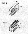
- FIG. 3 a flat plate attached to top portion of container or dispenser 1 B and consists of two horizontal and vertical lines. It has two small slots, 28 and 29 , on top left, see FIG. 3 :
- FIG. 3 a square empty container or dispenser
- container 1 C a small container that will attach to container or dispenser 1 B from bottom of both containers 1 B and 1 C.
- the interior of container 1 C is an empty space, see FIG. 3 :
- top portion of container 1 A in FIG. 4 shows the components in the panel:
- FIG. 4 shows empty container box 1 C with its:
- the panel 1 D shows its components and attachment in FIG. 4 :
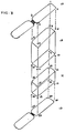
- FIG. 10-13 represent container or dispenser 1 A's:
- the second part of Glotite is container 1 C which has an empty space inside of its interior designed to store used wipes.
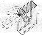
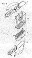
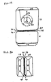
- FIG. 2 shows Glotite container from top right angle view.
- FIG. 3 shows the view of Glotite assembly only, not all external and internal parts ⁇ and components ⁇ .
- Assembly of Glotite container consist of four parts: ⁇ a flat panel that attaches to container or dispenser 1 B ⁇ 1 A, ⁇ a larger container or dispenser ⁇ 1 B, ⁇ a smaller container that attaches to container 1 B ⁇ 1 C, ⁇ and flat panel with its attachments ⁇ 1 D.
- 1 A [the flat panel] is the part that goes to the top portion of ⁇ container or dispenser ⁇ 1 B. 1 A snaps in securely to the top of container or dispenser 1 B by threads built around the ⁇ interior ⁇ flat panel. 1 A with its four corners and lines; 1 , 2 , 3 , 4 snaps at ⁇ four corners ⁇ 5 , 6 , 7 , 8 location of 1 B.
- 1 B is the main unit ⁇ where 1 B ⁇ ⁇ and 1 C will attach to it as an accessory to make it as one unit or product ⁇ .
- 1 C ⁇ smaller container ⁇ will attach to 1 B container by its four lines and corners; 13 , 14 , 15 , 16 to 1 B securely. This will be explained in later pages
- 1 D will snap by its four corners and lines to 1 C at its four corners; 17 , 18 , 19 , 20 .
- FIG. 4 on page 4 of drawings gives a view of non-assembly of ⁇ Glotite ⁇ ⁇ Glotite's ⁇ four different parts; 1 A, 1 B, 1 C and 1 D.
- 1 A is a flat panel and has threads inward around it to enable it to snap easily and securely to the top portion of container [or dispenser] 1 B.
- 1 A has an open slot, 28 , to allow wipes to come upward through it and starch the wet wipes over another open slot, 29 , which is longer in length and has a blade, 30 , on it cut the desired wipes for use.
- joiner, 27 is connected by joiner, 27 , to its cover, 25 , which has a small bumpy pin, 26 , on its opening front and can easily be open by a push of finger upward and can be closed by a finger either by pushing down cover 25 or the pin 26 .
- Cover 25 is about ⁇ 0.4′′ ⁇ ⁇ 0.4-inch-deep ⁇ inside which provides comfortable setting to panel 1 A when is closed.
- Part 25 keeps the blade and fresh un cut ⁇ wip ⁇ ⁇ wipes ⁇ out of touch and securely covers them.
- Arrow 31 indicates the opening direction from right to left and arrow 32 the closing direction of 25 from left to right.
- the cap or cover 25 will snap securely to 1 B to keep the small exposed ⁇ wip ⁇ ⁇ wipe ⁇ coming out through slot 28 fresh for net use.
- Container Inside container is empty spaced to hold ⁇ the ⁇ ⁇ wips ⁇ wipes. It is open from top and sealed from bottom to enable to snap flat panel 1 A on its top and connect container 1 C to its bottom by built in sliding slots horizontally at the bottom of container 1 B and 1 C exterior by 37 and 38 of 1 B to 39 and 40 of 1 C.
- 1 B also has a sliding slots 33 on its right-hand side of its back exterior and 36 which located vertically on the left-hand side in the exterior. These two sliders will allow another Glotite container to be connected back to back. The reason is to carry two containers as on unit rather than separate ones. It's a matter of continence and manageability.
- 1 B has two other sliding slots for different functionality in its interior ⁇ on ⁇ located vertically inside the back panel and is ⁇ starch ⁇ ⁇ starched ⁇ to the middle section and ⁇ ther ⁇ ⁇ the other ⁇ vertically located in the ⁇ back front ⁇ ⁇ back-front ⁇ panel starching to the middle section.
- Container 1 C is an accessory attached to container 1 B to make it as one unit. It is ⁇ and ⁇ ⁇ an ⁇ empty container to allow user to store ⁇ wips ⁇ ⁇ wipes ⁇ after usage and store them inside where trashcans ⁇ is ⁇ ⁇ would not be ⁇ immediately available.
- the cover at the bottom easily snaps out by finger through pushing its front pin 48 upward to open the cover to dispose the used ⁇ wips ⁇ ⁇ wipes ⁇ then snap or close the cover back to the original position for the next use.
- 1 C in FIG. 4 consists of open slot at its bottom part, 42 , to allow used wet ⁇ wips ⁇ ⁇ wipes ⁇ to be stored but the bottom part is sealed and has horizontal sliding ⁇ slots ⁇ ⁇ slot ⁇ 39 which will slide to 37 of 1 B, and 40 of container 1 C which slide in 38 of 1 B.
- the bottom portion of 1 C ⁇ in FIG. 4 ⁇ is shaded to show that that part is sealed.
- the sides of container 1 C are shown by 41 and 43 .
- the only part of 1 C which is open to accept flat panel 1 D and used wet ⁇ wips ⁇ ⁇ wipes ⁇ is 42 .
- Flat panel 1 D has inward threads around it and is to allow 1 D to snap to 42 of container 1 C. This option might be eliminated if joiner constructed directly to the left side of 1 C shown by 43 .
- 1 D flat panel is attached to 46 cover by joiner 44 to allow 46 to cover 42 to keep the use ⁇ wips ⁇ ⁇ wipe ⁇ in its place.
- the cover 46 has a pin in front of it 48 for easy opening of the cover. Cover 46 also has two separate small bumps on the exterior to allow Glotite to sit vertically on the surface and is shown by 45 and 47 .
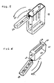
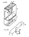
- FIG. 5 gives a view of containers 1 B and 1 C which are detached from each other to indicate the assembled parts on their appropriate places.
- 1 A panel is attached to container 1 B from top snapped securely on the top of 1 B container. It also shows its cover, 25 , connected to 1 A in another end by joiner.
- the arrow 31 shows the direction of its opening cover and arrow 32 shows the closing direction from left to right.
- the pin, 26 shows it is attached to the opening side of 25 to let the user to push it upward by ⁇ tomb ⁇ ⁇ thumb ⁇ .
- the sliders 33 and 36 are ⁇ located ⁇ in the back exterior panel of container 1 B to allow another container to be attach to it.
- Sliding slot 34 located in the middle in the back exterior and sliding slot 35 located in the middle of the front in its interior to allow to insert ⁇ wips ⁇ wipes.
- Sliding slot 37 located horizontally in its upper and sliding slot 38 located horizontally in its lower exterior side at the bottom of container 1 B. This will allow 1 C to be attached to 1 B, 37 and 38 , through its own sliding slots of 39 and 40 .
- Sliding slot 39 will slide through 37 and sliding slot 40 goes through sliding slot 38 of container 1 B at the same time.
- the ⁇ right hand ⁇ ⁇ right-hand ⁇ side, 41 , and left hand side of 1 C 43 and 42 which is the top portion of container 1 C allow used ⁇ wips ⁇ ⁇ wipes ⁇ to be stored and close by cover 46 .
- Cover 46 can be easily open by pushing pin 48 upward by the right thumb.
- the cover 46 is connected to 1 C to close and open the 46 by its pin 48 .
- the small little bumps 47 and 45 are on the exterior if 46 to allow Glotite to stand vertical on a surface easily.
- 49 and 50 are the ⁇ arows ⁇ ⁇ arrows ⁇ that indicates the directions of opening from right to left and the direction of closing cover from left to right in downward position to secure the used ⁇ wips ⁇ ⁇ wipes ⁇ and to dispose them.
- FIG. 7 views Glotite from ⁇ top ⁇ left angle ⁇ , top ⁇ showing interior and exterior of container 1 B itself without ⁇ proving ⁇ ⁇ providing ⁇ other parts.
- the cap or cover 25 shows the closed position on the top of container 1 B.
- Cover 25 has ⁇ 0.4′′ ⁇ ⁇ 0.4 inch ⁇ deep interior to allow to sit on top of 1 B ⁇ comfortibility ⁇ ⁇ comfortably ⁇ to provide space needed to secure top components easily.
- the bottom of container 1 B is shaded in dark.
- Container 1 C in FIG. 8 which is shaded on top shows the bottom and interior 46 positioned at the bottom.
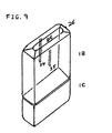
- Container 1 B FIG. 9 , shows left side view of its top 25 and its pin 26 in closing position with sliding slots 34 on the left in back interior and 35 sliding slot in the front panel's interior right in the middle.
- the two container 1 B and 1 C connected from bottom through their exterior sliding slots.
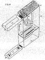
- Glotite 1 B is attached to container 1 C connected from top side view to show its cover 25 with its pin 26 in open position, and to emphasize the way wet ⁇ wips ⁇ ⁇ wipes ⁇ pulley is connected to sliding slots 34 and 35 in the interior of container 1 B.
- the sliding slot 34 located in the interior back side of 1 B and slot 35 in the back side of 1 B interior front panel.
- Pulley 51 ⁇ has been slided ⁇ ⁇ slides ⁇ to 34 and 35 from top by its pin sticking out from its side, 52 and 53 , in which the pulley 51 will slide down all the way to the end of 34 and 35 as wet ⁇ wips ⁇ ⁇ wipes ⁇ pulled out.
- FIG. 11 and FIG. 12 shows pulley's pins in different position and sides.
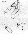
- the top portion of container 1 C in FIG. 13 is in upward position to show the exterior from left angle.
- the little bumps, 45 and 47 are ⁇ located ⁇ in the exterior of 46 with its pin 48 on the right side.
- FIG. 14 The correct position of container 1 C is displayed in FIG. 14 where its bottom is in upward position and is shaded in dark with its sliding slots shown horizontally, 39 and 40 , to represent the sealed part of 1 C.
- the top interior, 46 is at the bottom in correct position with. its little bombs 45 and 47 on top of it to allow Glotite to sit upward position.
- Glotite 1 B in FIG. 15 which is the main unit has two sliding slots positioned Horizontally, 37 and 38 , in its bottom exterior to allow 1 C to be connected.
- top ⁇ , ⁇ side and interior of 1 B in FIG. 15 gives a view from top left hand side angle.
- the cap or cover 25 is in open position with its opening pin 26 on its left front.
- the arrow 31 shows the direction of opening position from right to left and arrow 32 indicates the closing position from left to right.
- 1 A flat panel is attached to 1 B and is secured by its build in threads in 1 A and 1 B.
- the slider slots 33 on the ⁇ right hand ⁇ ⁇ right-hand ⁇ side of back exterior and 36 on the ⁇ left hand ⁇ ⁇ left-hand ⁇ side of back exterior are shown in FIG. 15 to be used any time user feels to attach another Glotite back to back to another unit.
- FIG. 15 only sliding slot 34 is shown to show pulley 51 with its pin 53 and its ⁇ wips ⁇ ⁇ wipes ⁇ 54 attachment to give a different view.
- FIG. 16 shows the same FIG as of FIG. 15 with only difference that container 1 C is attached to 1 B in open position of their caps and ⁇ cover ⁇ ⁇ covers ⁇ .
- the cap or cover 25 is open with its pin 26 on its ⁇ let ⁇ ⁇ left, ⁇ right in the middle.
- the interior viewed from let hand side from top with one sliding slot 33 on the exterior right hand side of 1 B back panel and the other sliding slot 36 on the ⁇ [back panel ⁇ ⁇ back-panel ⁇ exterior on far left.
- the interior cap or cover 25 is ⁇ 0.4′′ ⁇ ⁇ 0.4 inch ⁇ deep that allows a secure and comfortable space for parts on top of flat panel 1 A.
- container 1 C is attached to 1 B through ⁇ FIG. 16 ⁇ their sliding slots of 37 and 38 of 1 B and 39 and 40 of container 1 C.
- Both 1 B and 1 C bottom position are sealed to enable to construct sliders 37 , 38 , 39 , and 40 on their exterior horizontally.
- the top portion of 1 C is an open space where cap or cover 40 is open and the top exposed.
- the cover is open with its pin to allow user to open by his/her ⁇ tomb ⁇ ⁇ thump ⁇ the pin 48 easily.
- the cover 46 also has two bumps 47 and 45 in the exterior to allow Glotite with attached 1 C to sit vertically and comfortably on the surface.
- FIG. 17 is exactly as FIG. 15 except that the cover 25 shows in close position.
- the interior components show cap or cover 25 with its opening pin 26 and sliding slot 34 for pulley where pulley 51 with its pin 53 , the ⁇ right hand ⁇ ⁇ right-hand ⁇ side pin, is attached to the bottom end of 34 .
- the ⁇ wip ⁇ ⁇ wipe ⁇ is wrapped around pulley 51 and moves in circular motion as the ⁇ wip ⁇ ⁇ wipe ⁇ is pulled upward from top through slot 28 over slot 29 to be cut by blade 30 .
- FIG. 18 shows closed cover of container 1 B with its exposed interior components. It is exactly as FIG. 17 with only two difference: one ⁇ wip ⁇ ⁇ wipe ⁇ 54 is cut at cutting slot 29 and the rest of the ⁇ wip ⁇ ⁇ wipe ⁇ as shown is no longer there. the other difference i ⁇ that container 1 C is added.
- FIG. 18 shows container 1 B and 1 C connection points at sliding slots 37 , 38 , 39 and 40 where 1 C joins to 1 B from bottom by sliding exterior sliders 38 and 37 Into the bottom exterior of 1 B 39 and 40 .
- Container 1 B in FIG. 19 is attached to its accessory container 1 C at the bottom. It shows front view of 1 B and 1 C where 1 B cover 25 shows upward on top and 1 C cover 46 shows down ward and in closed position.
- FIG. 19 shows sliding slot 34 from front view with pulley 51 and one of its pin 53 with its wrapped around ⁇ wip ⁇ ⁇ wipe ⁇ 54 attached to it.
- the pulley with wet ⁇ wips ⁇ ⁇ wipes ⁇ is pulled upward to show where the other side of ⁇ wip ⁇ ⁇ wipe ⁇ 54 will end up.
- the two containers are joined by their sliders 37 , 38 , 39 and 40 horizontally.
- FIG. 20 two identical Glotite containers marked by 1 B and 2 B been attached by their ⁇ back cover ⁇ ⁇ back-cover ⁇ sliding slots 37 , 38 , 39 and 40 . It shows the above view how they joined and looked like. Their caps are also shown in the FIG. 20 .
- FIG. 21 shows container 1 B from front view with its cover 25 on top and horizontal sliding slots 37 and 38 at the bottom.
- Pulley 51 with its one of its pin 53 with its wrapped around wet ⁇ wip ⁇ ⁇ wipe ⁇ 54 is positioned at bottom end of sliding slot 34 which designed specifically to hold pulley securely without moving the pulley upward ⁇ When ⁇ the ⁇ wips ⁇ ⁇ wipes ⁇ 54 from top 1 A.
- the interior back panel of sliding slots of 1 B and 2 B shown in FIG. 22 located right in the middle section with pulley sliders constructed differently than back exterior sliders in that the pulley sliders locks the pulley at the end to prevent pulley to be pulled up.
- FIG. 23 shows the side angle ⁇ wiew ⁇ ⁇ view ⁇ from front shows on FIG. 23 ⁇ . ⁇ ⁇ the ⁇ sliding slots of 34 and 35 located in interior of 1 B back and front panels.
- the pulley 51 is hanging right in the middle connected to 34 and 35 by its pins 53 and 52 .
- the pulley will rotate freely in circular motion as it turns.
- the FIG. 23 shows the cover from above.
- FIG. 24 shows container 1 B front view with its interior exposed. Cover 25 ⁇ with ⁇ ⁇ with ⁇ its opening pin 26 located on top.
- the sliding slots 37 and 38 are horizontally at the bottom.
- the interior back side 34 is starched to the middle to hold pulley by its pin 53 securely with pulley's wet ⁇ wips ⁇ ⁇ wipes ⁇ wrapped around it to move in circular motion freely.
- the ⁇ wips ⁇ ⁇ wipes ⁇ comes ⁇ though ⁇ ⁇ through ⁇ open slot 28 goes over longer slot 29 to be cut by its blade 30 .
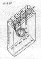
- FIG. 25 A completed view of Glotite disinfecting ⁇ wips ⁇ ⁇ wipes ⁇ container is shown on FIG. 25 with its closed cap on top and 1 C at its bottom connected by their slnts 37 , 38 , 39 and 40
- Container 1 C is in correct position where top with its cover 46 facing downward with exposed joiner 44 on the ⁇ left hand ⁇ ⁇ left-hand ⁇ side and opening pin 48 on the right.
- Joiner 44 attaches cover 46 to the top of the 1 C by snapping into it.
- Joiner 44 is flexible of soft plastics material enables cover to open and close while cover 46 is in ⁇ in place ⁇ tacked.
- Container 1 C is designed to accompany container 1 B as an empty space to store used and unclean ⁇ wips ⁇ ⁇ wipes ⁇ in its compartment when ⁇ trash can ⁇ ⁇ trashcans ⁇ ⁇ is ⁇ ⁇ are ⁇ not available immediately. The used ⁇ wips ⁇ ⁇ wipes ⁇ can be taken out by opening cover 46 to dispose of it. Then close the cover 46 for later use.
- Container 1 C is washable and reusable.
- Container 1 B is the main unit that houses fresh wet ⁇ wips ⁇ ⁇ wipes ⁇ in its compartment designed for this purpose.
- the FIG. 25 shows closed cover in its external setting with its pin. Its opening pin 51 ⁇ is ⁇ in front right hand side of it. The pin enables user to open upward by pressing his/her ⁇ tumb ⁇ ⁇ thumb ⁇ against it. To close the cover 25 one need to push cover 25 downward from left to right with his/her finger.
- FIG. 25 the internal components are exposed to show how the components inside will look, work and ⁇ are ⁇ located.
- Another sliding slot 35 is constructed on the interior panel of front interior back side panel the same way as ⁇ (34) ⁇ ⁇ 34 ⁇ and all the way to the middle section to enable ⁇ other ⁇ ⁇ another ⁇ end of 51 which is 53 to sit at the end of ⁇ this ⁇ ⁇ these ⁇ two narrow straight lines with closed end with ⁇ 0.1′′ ⁇ ⁇ 0.1 inch ⁇ deep inside to allow 51 easily rotate on 34 and 35 by 51 ends pins, 52 and 53 , see FIG. 25 .
- FIG. 26 shows only where the pulley 51 with its left pin 52 and right pin ⁇ 53 ⁇ will sit and rotates.
- FIG. 26 shows front side view of container 1 B with its interior sliding clots purposefully constructed to hold a pulley with its ⁇ wips ⁇ ⁇ wipes ⁇
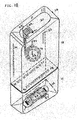
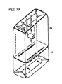
- FIG. 27 shows the drawing of a completed internal view from top left hand side to show viewers the components of container 1 B and 1 C as one unit or product. Specification not shown here intentionally because it was viewed in FIG. 4 and FIG. 25 . And ⁇ also ⁇ [also, ⁇ to show a more softer view of the product.
- FIG. 28 ⁇ on page 18 ⁇ shows the external view of Glotite product where container 1 B and container 1 C combined.
Landscapes
- Engineering & Computer Science (AREA)
- Mechanical Engineering (AREA)
- Health & Medical Sciences (AREA)
- Public Health (AREA)
- Closures For Containers (AREA)
Abstract
The Glotite Disinfecting Wet Wipes Container/Dispenser consist of four parts: 1A, 1B, 1C, and 1D.
Container 1B which is the main unit accepts 1A to its top portion securely. Container or dispenser 1B houses wipes wrapped around a pulley. Flat panel 1A is the portion that wipes will be pulled from to used. Container 1C is the empty container that will attach to the bottom of the container or dispenser 1B through their external sliding slots vertically positioned at the bottom of the container 1B and 1C.
Container 1B and 1C have cover 25 and 46 respectively. Cover 25 is used to open the lid or the cover to enable one to pull out the wipes to use. Container 1C's 46 used to open the lid to store the used wipes and close it after storing wipes.
Description
- 1A, a flat plate attached to top portion of container or
dispenser 1B and consists of two horizontal and vertical lines. It has two small slots, 28 and 29, on top left, seeFIG. 3 : -
- 1: top right hand corner
- 2: top left hand corner
- 3: bottom right hand corner
- 4: bottom left hand corner
- 1B, a square empty container or dispenser, see
FIG. 3 : -
- 5: top right corner where 1 will attach to it
- 6: lower right hand corner where 3 will attach to it
- 7: lower to left corner where 4 will attach to it
- 8: top left corner where corner 2 will attach to it
- 9: top bottom corner of container or
dispenser 1B will connect corner 14 - 10: lower bottom corner of container or
dispenser 1B wherecorner 13 will attach to it - 11: lower
left bottom 1B where corner 15 will attach to it - 12: upper bottom left corner of 1B where
corner 16 of container ordispenser 1C will attach to it.
- 1C, a small container that will attach to container or
dispenser 1B from bottom of bothcontainers container 1C is an empty space, seeFIG. 3 : -
- 13: lower
top corner container 1C where will attach to the corner of 1B to it - 14: upper right corner of 1C where will attach to
corner 9 of Container ordispenser 1B - 15: lower top left corner of 1C where will join to the corner 11 of 1B
- 16: upper top
right corner 1C will attach to corner 12 of 1B - 17: lower right corner bottom of 1C where corner 21 of flat panel of 1D will be attach
- 18: upper right corner of
container 1C will attach to thecorner 22 in upper right corner of 1D - 19: lower left corner of
container 1C will attach to lowerleft corner 23 of panel 1D - 20: lower right corner of
container 1C will attach to upperright corner 24 of 1D
- 13: lower
- 1D, a flat panel just like flat panel 1A of container or
dispenser 1B where It is attached to the bottom ofcontainer 1C, seeFIG. 3 : -
- 21: lower right corner of 1D will attach to upper
right corner 17 of container ordispenser 1C - 22: upper right corner of 1D will attach to upper right bottom corner of container of 18 of
container 1C - 23: lower left corner of 1D will attach to the bottom lower left corner of
container 1C - 24: upper right corner of 1D will attach to lower
left corner 20 ofcontainer 1C
- 21: lower right corner of 1D will attach to upper
- top portion of container 1A in
FIG. 4 shows the components in the panel: -
- 25: cap or cover of panel 1A in
container 1B - 26: a tip or pin on the right-hand side of container or dispenser 1A where it is designed to help user to open the cover by their tip of finger
- 27: joiner that connects container or dispenser 1A to 25
- 28: a horizontal slot will allow wipes to come out through it
- 29: a small horizontal slot or space that will allow a small blade to move freely on it from right to left and left to right
- 30: a small sharp blade on 29
- 31: shows and indicates the direction of 25 open position
- 32: shows and indicates the closing direction of 25
- 25: cap or cover of panel 1A in
- container or
dispenser 1B inFIG. 4 shown with its: -
- 33: vertical sliding slot located in the back side exterior and on the right hand side
- 34: vertical sliding slot allows pulley's pin to enter downward
- 35: vertical sliding slot located in the back of front panel of container or
dispenser 1B in the middle - 36: sliding slot located in the right-hand side and in the back panel of
container 1B exterior - 37: horizontal sliding slot at the bottom of container or
dispenser 1B - 38: horizontal sliding slot at the bottom of container or
dispenser 1B
-
FIG. 4 showsempty container box 1C with its: -
- 39: horizontal sliding slot at the bottom
- 40: horizontal sliding slot at the bottom
- 41: right side of
container 1C - 42: open space on top of the container at the bottom position
- 43: left side of the
container 1C
- the panel 1D shows its components and attachment in
FIG. 4 : -
- 44: joiner that joins panel D to cap or cover 46
- 45: a flat bump on the left-
hand side 46 along with anotherflat bump 47 on the right - 46: cove of panel 1D
- 47: a flat bump on the right-hand side of
cover 46 - 48: a tip or pin to assist users to open
cover 46 easily with tomb - 49: shows the closing direction of 46
- 50: shows the direction of
cover 46
-
FIG. 10-13 represent container or dispenser 1A's: -
- 51:
pulley 51 pulley'spin - 52: one of pulley's pin sticking out from its side
- 53: another pulley's pin sticking out from the other side of it
- 51:
- wet wipes in circular motion inside container or
dispenser 1B, as shown InFIG. 15 , with its: -
- 54: wet wipes wrapped around pulley 51)
- Glotite disinfecting wipes container is cleaning hands, surface and objects. It consists of two parts:
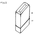
container 1B which is the main unit that holds the wipes in its interior section right in the middle of it. It is a larger unit, 2 inches in height, 2-inch in width and 0.14=⅛ inches deep in square shape as shown inFIG. 1 in drawing section. - The second part of Glotite is
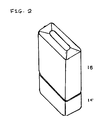
container 1C which has an empty space inside of its interior designed to store used wipes.FIG. 2 shows Glotite container from top right angle view. -
FIG. 3 shows the view of Glotite assembly only, not all external and internal parts {and components}. Assembly of Glotite container consist of four parts: {a flat panel that attaches to container ordispenser 1B} 1A, {a larger container or dispenser} 1B, {a smaller container that attaches tocontainer 1B} 1C, {and flat panel with its attachments} 1D. - 1A [the flat panel] is the part that goes to the top portion of {container or dispenser} 1B. 1A snaps in securely to the top of container or
dispenser 1B by threads built around the {interior} flat panel. 1A with its four corners and lines; 1,2,3,4 snaps at {four corners} 5,6,7,8 location of 1B. - As mentioned previously 1B is the main unit {{where 1B}} {and 1C will attach to it as an accessory to make it as one unit or product}.
- 1C {smaller container} will attach to 1B container by its four lines and corners; 13,14,15,16 to 1B securely. This will be explained in later pages
- 1D will snap by its four corners and lines to 1C at its four corners; 17,18,19, 20.
-
FIG. 4 onpage 4 of drawings gives a view of non-assembly of {{Glotite}} {Glotite's} four different parts; 1A, 1B, 1C and 1D. - 1A is a flat panel and has threads inward around it to enable it to snap easily and securely to the top portion of container [or dispenser] 1B.
- 1A has an open slot, 28, to allow wipes to come upward through it and starch the wet wipes over another open slot, 29, which is longer in length and has a blade, 30, on it cut the desired wipes for use.
- 1A is connected by joiner, 27, to its cover, 25, which has a small bumpy pin, 26, on its opening front and can easily be open by a push of finger upward and can be closed by a finger either by pushing down
cover 25 or thepin 26. -
Cover 25 is about {{0.4″}} {0.4-inch-deep} inside which provides comfortable setting to panel 1A when is closed. -
Part 25 keeps the blade and fresh un cut {{wip}} {wipes} out of touch and securely covers them.Arrow 31 indicates the opening direction from right to left andarrow 32 the closing direction of 25 from left to right. - The cap or cover 25 will snap securely to 1B to keep the small exposed {{wip}} {wipe} coming out through
slot 28 fresh for net use. - Inside container is empty spaced to hold {the} {{wips}} wipes. It is open from top and sealed from bottom to enable to snap flat panel 1A on its top and connect
container 1C to its bottom by built in sliding slots horizontally at the bottom ofcontainer - 1B also has a sliding
slots 33 on its right-hand side of its back exterior and 36 which located vertically on the left-hand side in the exterior. These two sliders will allow another Glotite container to be connected back to back. The reason is to carry two containers as on unit rather than separate ones. It's a matter of continence and manageability. - 1B has two other sliding slots for different functionality in its interior {{on}} located vertically inside the back panel and is {{starch}} {starched} to the middle section and {{ther}} {the other} vertically located in the {{back front}} {back-front} panel starching to the middle section.
-
Container 1C is an accessory attached tocontainer 1B to make it as one unit. It is {{and}} {an} empty container to allow user to store {{wips} {wipes} after usage and store them inside where trashcans {{is}} {would not be} immediately available. The cover at the bottom easily snaps out by finger through pushing itsfront pin 48 upward to open the cover to dispose the used {{wips}} {wipes} then snap or close the cover back to the original position for the next use. - 1C in
FIG. 4 consists of open slot at its bottom part, 42, to allow used wet {{wips}} {wipes} to be stored but the bottom part is sealed and has horizontal sliding {{slots}} {slot} 39 which will slide to 37 of 1B, and 40 ofcontainer 1C which slide in 38 of 1B. The bottom portion of 1C {inFIG. 4 } is shaded to show that that part is sealed. The sides ofcontainer 1C are shown by 41 and 43. The only part of 1C which is open to accept flat panel 1D and used wet {{wips}} {wipes} is 42. - Flat panel 1D has inward threads around it and is to allow 1D to snap to 42 of
container 1C. This option might be eliminated if joiner constructed directly to the left side of 1C shown by 43. - 1D flat panel is attached to 46 cover by joiner 44 to allow 46 to cover 42 to keep the use {{wips}} {wipe} in its place. The
cover 46 has a pin in front of it 48 for easy opening of the cover.Cover 46 also has two separate small bumps on the exterior to allow Glotite to sit vertically on the surface and is shown by 45 and 47. -
FIG. 5 gives a view ofcontainers - 1A panel is attached to
container 1B from top snapped securely on the top of 1B container. It also shows its cover, 25, connected to 1A in another end by joiner. Thearrow 31 shows the direction of its opening cover andarrow 32 shows the closing direction from left to right. The pin, 26, shows it is attached to the opening side of 25 to let the user to push it upward by {{tomb}} {thumb}. - The
sliders container 1B to allow another container to be attach to it. - Sliding
slot 34 located in the middle in the back exterior and slidingslot 35 located in the middle of the front in its interior to allow to insert {{wips}} wipes. Slidingslot 37 located horizontally in its upper and slidingslot 38 located horizontally in its lower exterior side at the bottom ofcontainer 1B. This will allow 1C to be attached to 1B, 37 and 38, through its own sliding slots of 39 and 40. Slidingslot 39 will slide through 37 and slidingslot 40 goes through slidingslot 38 ofcontainer 1B at the same time. - In
FIG. 6 sliding slots of 39 and 40 at 1C's bottom that will slide to 37 and 38 at the same time becomes one with different functionality. - The {{right hand}} {right-hand} side, 41, and left hand side of
1 C container 1C allow used {{wips}} {wipes} to be stored and close bycover 46. -
Cover 46 can be easily open by pushingpin 48 upward by the right thumb. - The
cover 46 is connected to 1C to close and open the 46 by itspin 48. - The small
little bumps -
FIG. 7 views Glotite from {top} left angle {{, top}} showing interior and exterior ofcontainer 1B itself without {{proving}} {providing} other parts. - The cap or cover 25 shows the closed position on the top of
container 1B.Cover 25 has {{0.4″}} {0.4 inch} deep interior to allow to sit on top of 1B {{comfortibility}} {comfortably} to provide space needed to secure top components easily. - The bottom of
container 1B is shaded in dark. -
Container 1C inFIG. 8 which is shaded on top shows the bottom and interior 46 positioned at the bottom. -
Container 1B,FIG. 9 , shows left side view of its top 25 and itspin 26 in closing position with slidingslots 34 on the left in back interior and 35 sliding slot in the front panel's interior right in the middle. The twocontainer -
Glotite 1B,FIG. 10 , is attached tocontainer 1C connected from top side view to show itscover 25 with itspin 26 in open position, and to emphasize the way wet {{wips}} {wipes} pulley is connected to slidingslots container 1B. - The sliding
slot 34 located in the interior back side of 1B andslot 35 in the back side of 1B interior front panel. - Pulley 51 {{has been slided}} {slides} to 34 and 35 from top by its pin sticking out from its side, 52 and 53, in which the
pulley 51 will slide down all the way to the end of 34 and 35 as wet {{wips}} {wipes} pulled out. -
FIG. 11 andFIG. 12 shows pulley's pins in different position and sides. - The top portion of
container 1C inFIG. 13 is in upward position to show the exterior from left angle. The little bumps, 45 and 47, are {{located}} in the exterior of 46 with itspin 48 on the right side. - It also shows exterior of sliding 39 and 40 at the bottom position of 1C.
- The correct position of
container 1C is displayed inFIG. 14 where its bottom is in upward position and is shaded in dark with its sliding slots shown horizontally, 39 and 40, to represent the sealed part of 1C. - The top interior, 46, is at the bottom in correct position with. its
little bombs -
Glotite 1B inFIG. 15 which is the main unit has two sliding slots positioned Horizontally, 37 and 38, in its bottom exterior to allow 1C to be connected. - The top {{,}} side and interior of 1B in
FIG. 15 gives a view from top left hand side angle. - The cap or cover 25 is in open position with its
opening pin 26 on its left front. - The
arrow 31 shows the direction of opening position from right to left andarrow 32 indicates the closing position from left to right. - 1A flat panel is attached to 1B and is secured by its build in threads in 1A and 1B. On the 1A panel there are 28 and 29 located horizontally on the top left hand side to allow {{wips}} {wipes} to come through 28 to be pulled toward 29 which has {a} blade built on it, 30, to be cut by moving blade direction from either left to right to right to left.
- After cutting the {{wip}} {wipe} very small portion of {{wip}} {wipe} 54 will remain in
slot 28 for next time usage. The cap or cover will protect the freshness of the remaining {{wip/s}} {wipe/s}. - The
slider slots 33 on the {{right hand}} {right-hand} side of back exterior and 36 on the {{left hand}} {left-hand} side of back exterior are shown inFIG. 15 to be used any time user feels to attach another Glotite back to back to another unit. inFIG. 15 only slidingslot 34 is shown to showpulley 51 with itspin 53 and its {{wips}} {wipes} 54 attachment to give a different view. -
FIG. 16 shows the same FIG as ofFIG. 15 with only difference thatcontainer 1C is attached to 1B in open position of their caps and {{cover}} {covers}. - the cap or cover 25 is open with its
pin 26 on its {{let}} {left,} right in the middle. The interior viewed from let hand side from top with one slidingslot 33 on the exterior right hand side of 1B back panel and the other slidingslot 36 on the {[back panel}} {back-panel} exterior on far left. - In the back panel of interior of 1B sliding slot lays vertically from top to the middle of the back panel of
container 16. The slidingslide 34 will holdpulley 51 with its {{wips}} {wipes} wrapped around it through pulley's sticking out pin form itsside 53. - Only one sliding
slot 34 and only one pulley'spin 53 with wet {{wip}} {wipe} 54 is shown from certain angle to show the connection. The pulley moves freely at the end of sliding slot and gets locked at the bottom to prevent pulley moving upward but still move in circular motion from left to right to allow {{wips}} {wipes} to be pulled upward throughopen slot 28 and to pulled over anotherslot 29 to be cut by itsblade 30. Theblade 30 will go any direction horizontally. - The interior cap or cover 25 is {{0.4″}} {0.4 inch} deep that allows a secure and comfortable space for parts on top of flat panel 1A.
-
container 1C is attached to 1B through {FIG. 16 } their sliding slots of 37 and 38 of 1B and 39 and 40 ofcontainer 1C. - Both 1B and 1C bottom position are sealed to enable to construct
sliders - the cover is open with its pin to allow user to open by his/her {{tomb}} {thump} the
pin 48 easily. Thecover 46 also has twobumps -
FIG. 17 is exactly asFIG. 15 except that thecover 25 shows in close position. The interior components show cap or cover 25 with itsopening pin 26 and slidingslot 34 for pulley wherepulley 51 with itspin 53, the {{right hand}} {right-hand} side pin, is attached to the bottom end of 34. The {{wip}} {wipe} is wrapped aroundpulley 51 and moves in circular motion as the {{wip}} {wipe} is pulled upward from top throughslot 28 overslot 29 to be cut byblade 30. -
FIG. 18 shows closed cover ofcontainer 1B with its exposed interior components. It is exactly asFIG. 17 with only two difference: one {{wip}} {wipe} 54 is cut at cuttingslot 29 and the rest of the {{wip}} {wipe} as shown is no longer there. the other difference iϵ thatcontainer 1C is added. -
FIG. 18 showscontainer slots exterior sliders 1 B - It also shows the used {{wips}} {wipes} 54 stored inside the interior of 1C where cap or cover 46 is closed {{.}} for functionality of 1B interior component, see
FIG. 16 . InFIG. 18 the interior components are exposed through, left side view,external cover 25. -
Container 1B inFIG. 19 is attached to itsaccessory container 1C at the bottom. It shows front view of 1B and 1C where 1B cover 25 shows upward on top and 1C cover 46 shows down ward and in closed position. - When user wants to store a used {{wip/s}} {wipes} after cleaning simply Flips the Glotite over in reverse, that is 1B will end up in downward position and 1C In upward position to allow used {{wip}} {wipe} to be placed inside the
container 1C. - The
FIG. 19 shows sliding slot 34 from front view withpulley 51 and one of itspin 53 with its wrapped around {{wip}} {wipe} 54 attached to it. The pulley with wet {{wips}} {wipes}} is pulled upward to show where the other side of {{wip}} {wipe} 54 will end up. - The two containers are joined by their
sliders - In
FIG. 20 two identical Glotite containers marked by 1B and 2B been attached by their {{back cover}} {back-cover} slidingslots FIG. 20 . -
FIG. 21 showscontainer 1B from front view with itscover 25 on top and horizontal slidingslots Pulley 51 with its one of itspin 53 with its wrapped around wet {{wip}} {wipe} 54 is positioned at bottom end of slidingslot 34 which designed specifically to hold pulley securely without moving the pulley upward {{When}} the {{wips}} {wipes} 54 from top 1A. - Two identical wet {{wips}} {wipes} containers marked by 1B and 2B on
FIG. 22 attached together by their sliding slots positioned horizontally at their slots marked for both 37 and 38. Since the attachment will be from their bottom therefore {{on}} {one} will be upward and one downward. - The interior back panel of sliding slots of 1B and 2B shown in
FIG. 22 located right in the middle section with pulley sliders constructed differently than back exterior sliders in that the pulley sliders locks the pulley at the end to prevent pulley to be pulled up. - The side angle {{wiew}} {view} from front shows on
FIG. 23 {{.}} {the} sliding slots of 34 and 35 located in interior of 1B back and front panels. Thepulley 51 is hanging right in the middle connected to 34 and 35 by itspins FIG. 23 shows the cover from above. -
FIG. 24 showscontainer 1B front view with its interior exposed. Cover 25 {{with}} {with} itsopening pin 26 located on top. The slidingslots side 34 is starched to the middle to hold pulley by itspin 53 securely with pulley's wet {{wips}} {wipes} wrapped around it to move in circular motion freely. The {{wips}} {wipes} comes {{though}} {through}open slot 28 goes overlonger slot 29 to be cut by itsblade 30. - A completed view of Glotite disinfecting {{wips}} {wipes} container is shown on
FIG. 25 with its closed cap on top and 1C at its bottom connected by theirslnts -
Container 1C is in correct position where top with itscover 46 facing downward with exposed joiner 44 on the {{left hand}} {left-hand} side andopening pin 48 on the right. - Joiner 44 attaches
cover 46 to the top of the 1C by snapping into it. Joiner 44 is flexible of soft plastics material enables cover to open and close whilecover 46 is in {{in place}} tacked.Container 1C is designed to accompanycontainer 1B as an empty space to store used and unclean {{wips}} {wipes} in its compartment when {{trash can}} {trashcans} {{is}} {are} not available immediately. The used {{wips}} {wipes} can be taken out by openingcover 46 to dispose of it. Then close thecover 46 for later use.Container 1C is washable and reusable. -
Container 1B is the main unit that houses fresh wet {{wips}} {wipes} in its compartment designed for this purpose. TheFIG. 25 shows closed cover in its external setting with its pin. Its opening pin 51 {is} in front right hand side of it. The pin enables user to open upward by pressing his/her {{tumb}} {thumb} against it. To close thecover 25 one need to pushcover 25 downward from left to right with his/her finger. - In
FIG. 25 the internal components are exposed to show how the components inside will look, work and {are} located. - On interior back panel there is a straight two line very close to each other is constructed all the way to the middle of the back panel. But their end is close and and joined together to enable this sliding
slot 34 to hold theleft pin 52 of {{wips}} {wipes}pulley 51 to hold securely without 51 getting pushed and moved upward. It {{also}} {also,} enables pulley to move in circular motion from left to right as {{wips}} {wipes} is pulled upward through a smallhorizontal opening 28, seeFIG. 15-17 . - The {{wip}} {wipe} from
slot 28 is pulled over another larger in length with blade on it to be cut seeFIG. 17 . - Another sliding
slot 35 is constructed on the interior panel of front interior back side panel the same way as {{(34)}} {34} and all the way to the middle section to enable {{other}} {another} end of 51 which is 53 to sit at the end of {{this}} {these} two narrow straight lines with closed end with {{0.1″}} {0.1 inch} deep inside to allow 51 easily rotate on 34 and 35 by 51 ends pins, 52 and 53, seeFIG. 25 . - We also see two sliding slots on
container 1B exterior back panel one 36 on the left and another one on the {{right hand}} {right-hand} side of the panel. This slidindslots in the back exterior of 1B Glotite enables to slide and attach another Glotite for easy carrying and convenience, seeFIGS. 25 and 20 . -
FIG. 26 shows only where thepulley 51 with itsleft pin 52 and right pin {53} will sit and rotates. - Sliding slots located on the middle of exterior back panel coming down straight to the middle section with closed end, see
FIG. 26 . - Inside 34 is {{0.1″}} {0.1 inch} deep to allow 34 to hold the
pin 52. Sliding slot is constructed the same way but on the back of front panel in its interior. The end allow {{other}} {another} end of 51 which is 53 to sit locked and {{be able to}} {can} rotate easily in circular motion from left to right as {{wips}} {wipes} on the pulley is pulled upward. -
FIG. 26 shows front side view ofcontainer 1B with its interior sliding clots purposefully constructed to hold a pulley with its {{wips}} {wipes} -
FIG. 27 shows the drawing of a completed internal view from top left hand side to show viewers the components ofcontainer FIG. 4 andFIG. 25 . And {{also}} [also,} to show a more softer view of the product. -
FIG. 28 {{on page 18}} shows the external view of Glotite product wherecontainer 1B andcontainer 1C combined. - These two last figures {{on
page 17 and 18} represent the container Glotite with wet {{wips}} {wipes} in 1B interior will sell to public for sanitizing hands, surface and objects safely. -
Drawing Index FIGS. Description page # 1 External view from left hand side 1 2 External view from right hand side 2 3 External components assembly 3 4 Components identification/internal parts 4 5 Container/dispenser 1B with open cover 25 5 6 Container 1C with open cover 46 5 7 Container/dispenser 1B with closed cover 25 6 8 Container 1C with closed cover 46 6 9 Glotite 1B with its Glotite accessory 1C 7 as one unit 10 Internal view of pulley 51 in container/ 8 dispenser 1B 11 View of pulley 8 12 Another view of pulley 8 13 Container 1C in upward position 9 14 Container 1C in downward position 9 15 internal view of container/dispenser 1B with 10 wipes 16 Internal view of container/dispenser 1B with 11 attached container 1C 17 Internal view of container 1B with wipes 12 in closed cap or cover 18 Internal view of container/dispenser 1B 13 with wipes attached to container1C 19 Front view of container/dispenser 1B with 14 its wipes inside with attached container 1C 20 Frontal view of container/dispenser 1B 14 attached to another one 21 Frontal view of container/dispenser 1B 15 22 Frontal view of two identical containers 1B 15 attached horizontally 23 Frontal internal view of container/dispenser 16 1B with pulley 51 inside 24 Frontal view of container/dispenser 1B with 16 pulley and container's closed cap/cover 25 25 A completed view of container/dispenser 1B 17 with its attachment 1C 26 Frontal view of pulley inside the container/ 17 dispenser 1B left angle
Claims (1)
1. Glotite disinfecting wet wipes container or dispenser is designed to be in two parts. The main and larger unit, 1B, is 2 inch in height, 2 inch in width and 0.14=⅛ deep. This container carries wet wipes wrapped around a pulley which is hanging right in the middle of Glotite interior by its two left and right sticking out pins to the interior back and front panels 1 in vertical position to be pulled up through a small horizontal opening, see FIG. 17 numbered 28, and cuts through a small blade, FIG. 17 numbered 30, located on horizontal slot in FIG. 17 numbered 29.
The second part, 1C, is invented be part of container 1B as a carrier of used wet wipes when one needed to store used wipes, and dispose them later. This empty container or dispenser 1C is 1 inch in height, 1 inch in width and 0.14=⅛ inch deep.
None of figures from 1 through 8 represent the actual size of the containers 1B and 1C. The two parts of Glotite act as one unit. The figures to show how the Glotite looks like and how they work and how technically is represented regardless of the figures sizes. Glotite physical representation shown from FIG. 1 thru FIG. 28 .
Glotite 1B container or dispenser is designed to be used anywhere, any time and any one (small children with adult supervision) to clean hands, surface and objects. The material of these container or dispenser is plastic and it is hard plastic. Container 1B constructed in such a way to keep this unique small wet wipes fresh at any time. The front panel is the same surface as the back panel except that the back panel has two s slots vertically positioned on its left and right side of its exterior.
The bottom part of container 1B also has two horizontal sliding slots as well. The back slots are designed attach another identical container or dispenser by sliding into other thru this vertical slots. The bottom horizontal sliding slots constructed to attach empty container 1C to the bottom of their ends. These containers or dispensers 1B and 1C can be used independently or together as one unit. But recommended to be used as one unit to give user ore advantage of storing wet wipes when trash is not available immediately.
This unique design in size and features in such a small compact container or dispenser and small wet wipes and its unique portability advantage in hard case makes this invention very useful and in demand by anyone. It is easy to use and to carry in pockets, handbags, bag packs, purses or any convenient places
Since it is small compact hard cased container, and is to clean hands, surface and objects, is perfect product to be used on daily basis at anytime and anywhere especially by kids, who are exposed to germs and bacteria by touching objects by their hands, it makes this product an absolute necessary to keep them safe from those germs and bacteria prevent them getting sick.
Glotite might come in one color or two color or mixture of colors. The price of this Unique product will depend on the cost of producing, manufacturing, retail and marketing factors. This unique product is not available in any retailers including small and big box retailers such as Costco, Walmart, Target, CVS, Sam's Club, Safeway's, Vons and many others.
This unique product, Glotite Disinfecting Wet Wipes container or dispenser, invented solely by me Al Zoghi all its parts and pieces and components, containers 1B and 1C, to be available through the retailers to sell and be marketed nationwide to consumers.
Glotite Disinfecting Wet Wipes container or dispenser is shown by physical drawings pages on drawing section as we advance through the pages.
Both containers designed to be one unit and one product for cleaning solution of hands, surface and objects.
Priority Applications (1)
| Application Number | Priority Date | Filing Date | Title |
|---|---|---|---|
| US15/288,082 US20180098673A1 (en) | 2016-10-07 | 2016-10-07 | Glotite disinfecting wips dispencer/container |
Applications Claiming Priority (1)
| Application Number | Priority Date | Filing Date | Title |
|---|---|---|---|
| US15/288,082 US20180098673A1 (en) | 2016-10-07 | 2016-10-07 | Glotite disinfecting wips dispencer/container |
Publications (1)
| Publication Number | Publication Date |
|---|---|
| US20180098673A1 true US20180098673A1 (en) | 2018-04-12 |
Family
ID=61829604
Family Applications (1)
| Application Number | Title | Priority Date | Filing Date |
|---|---|---|---|
| US15/288,082 Abandoned US20180098673A1 (en) | 2016-10-07 | 2016-10-07 | Glotite disinfecting wips dispencer/container |
Country Status (1)
| Country | Link |
|---|---|
| US (1) | US20180098673A1 (en) |
Cited By (2)
| Publication number | Priority date | Publication date | Assignee | Title |
|---|---|---|---|---|
| CN109229815A (en) * | 2018-09-27 | 2019-01-18 | 天津市艳胜工贸有限公司 | Environment-friendly type wet napkin package |
| GB2575328A (en) * | 2018-07-06 | 2020-01-08 | Lindstrom Ltd | Dispensing and disposal unit |
-
2016
- 2016-10-07 US US15/288,082 patent/US20180098673A1/en not_active Abandoned
Cited By (3)
| Publication number | Priority date | Publication date | Assignee | Title |
|---|---|---|---|---|
| GB2575328A (en) * | 2018-07-06 | 2020-01-08 | Lindstrom Ltd | Dispensing and disposal unit |
| GB2575328B (en) * | 2018-07-06 | 2022-09-28 | Lindstrom Ltd | Dispensing and disposal unit |
| CN109229815A (en) * | 2018-09-27 | 2019-01-18 | 天津市艳胜工贸有限公司 | Environment-friendly type wet napkin package |
Similar Documents
| Publication | Publication Date | Title |
|---|---|---|
| USD678763S1 (en) | Square plastic take-out salad container | |
| US10076170B2 (en) | Children's zipper pull | |
| USD641106S1 (en) | Cosmetic case | |
| USD682046S1 (en) | Storage container | |
| US20140251862A1 (en) | Pill containers with registers and methods | |
| US20080272024A1 (en) | Traveler's kitchen kit | |
| US20130233858A1 (en) | Container used for dispensing solid and liquid food items | |
| USD832656S1 (en) | Lunch box | |
| US7117991B2 (en) | Portable carrier | |
| US20180098673A1 (en) | Glotite disinfecting wips dispencer/container | |
| US20200348066A1 (en) | Ice cube tray | |
| JP3136919U (en) | Food container | |
| USD625597S1 (en) | Lidded container | |
| USD850813S1 (en) | Container for storing and dispensing liquid soap, shampoo and other cleaning substances | |
| CN211400495U (en) | Multifunctional storage basket | |
| KR20190049313A (en) | Toys detachable storage box | |
| US20220071363A1 (en) | Storage bag | |
| US576073A (en) | Dust-pan | |
| CN208080877U (en) | A kind of project cost storage device | |
| KR20100003482U (en) | Matting bag | |
| JP6419648B2 (en) | Pull-out storage case | |
| AU2006100021A4 (en) | Container openable and closable in different ways | |
| US20070079716A1 (en) | Rubber stamp package | |
| KR200491169Y1 (en) | Pouch for containing baby product | |
| US20140124526A1 (en) | Diaper and Wipe Dispenser |
Legal Events
| Date | Code | Title | Description |
|---|---|---|---|
| STPP | Information on status: patent application and granting procedure in general |
Free format text: NON FINAL ACTION MAILED |
|
| STCB | Information on status: application discontinuation |
Free format text: ABANDONED -- FAILURE TO RESPOND TO AN OFFICE ACTION |