US20180098505A1 - Baler with lockout valve - Google Patents
Baler with lockout valve Download PDFInfo
- Publication number
- US20180098505A1 US20180098505A1 US15/292,002 US201615292002A US2018098505A1 US 20180098505 A1 US20180098505 A1 US 20180098505A1 US 201615292002 A US201615292002 A US 201615292002A US 2018098505 A1 US2018098505 A1 US 2018098505A1
- Authority
- US
- United States
- Prior art keywords
- connecting rod
- baler
- plunger
- configuration
- fluid
- Prior art date
- Legal status (The legal status is an assumption and is not a legal conclusion. Google has not performed a legal analysis and makes no representation as to the accuracy of the status listed.)
- Granted
Links
- 239000012530 fluid Substances 0.000 claims abstract description 122
- 230000007423 decrease Effects 0.000 claims description 14
- 230000006835 compression Effects 0.000 description 47
- 238000007906 compression Methods 0.000 description 47
- 239000000463 material Substances 0.000 description 21
- 238000000034 method Methods 0.000 description 6
- 230000003247 decreasing effect Effects 0.000 description 3
- 230000005355 Hall effect Effects 0.000 description 2
- 230000001419 dependent effect Effects 0.000 description 2
- 230000003287 optical effect Effects 0.000 description 2
- 230000015572 biosynthetic process Effects 0.000 description 1
- 238000004364 calculation method Methods 0.000 description 1
- 238000006243 chemical reaction Methods 0.000 description 1
- 238000002485 combustion reaction Methods 0.000 description 1
- 230000008602 contraction Effects 0.000 description 1
- 238000006073 displacement reaction Methods 0.000 description 1
- 239000000446 fuel Substances 0.000 description 1
- 238000003306 harvesting Methods 0.000 description 1
- 238000004904 shortening Methods 0.000 description 1
- 239000010902 straw Substances 0.000 description 1
Images
Classifications
-
- A—HUMAN NECESSITIES
- A01—AGRICULTURE; FORESTRY; ANIMAL HUSBANDRY; HUNTING; TRAPPING; FISHING
- A01F—PROCESSING OF HARVESTED PRODUCE; HAY OR STRAW PRESSES; DEVICES FOR STORING AGRICULTURAL OR HORTICULTURAL PRODUCE
- A01F15/00—Baling presses for straw, hay or the like
- A01F15/04—Plunger presses
-
- A—HUMAN NECESSITIES
- A01—AGRICULTURE; FORESTRY; ANIMAL HUSBANDRY; HUNTING; TRAPPING; FISHING
- A01F—PROCESSING OF HARVESTED PRODUCE; HAY OR STRAW PRESSES; DEVICES FOR STORING AGRICULTURAL OR HORTICULTURAL PRODUCE
- A01F15/00—Baling presses for straw, hay or the like
- A01F15/04—Plunger presses
- A01F15/046—Plunger presses with press-boxes
-
- A—HUMAN NECESSITIES
- A01—AGRICULTURE; FORESTRY; ANIMAL HUSBANDRY; HUNTING; TRAPPING; FISHING
- A01F—PROCESSING OF HARVESTED PRODUCE; HAY OR STRAW PRESSES; DEVICES FOR STORING AGRICULTURAL OR HORTICULTURAL PRODUCE
- A01F15/00—Baling presses for straw, hay or the like
- A01F15/08—Details
- A01F15/0825—Regulating or controlling density or shape of the bale
-
- A—HUMAN NECESSITIES
- A01—AGRICULTURE; FORESTRY; ANIMAL HUSBANDRY; HUNTING; TRAPPING; FISHING
- A01F—PROCESSING OF HARVESTED PRODUCE; HAY OR STRAW PRESSES; DEVICES FOR STORING AGRICULTURAL OR HORTICULTURAL PRODUCE
- A01F15/00—Baling presses for straw, hay or the like
- A01F15/04—Plunger presses
- A01F15/042—Plungers
-
- A—HUMAN NECESSITIES
- A01—AGRICULTURE; FORESTRY; ANIMAL HUSBANDRY; HUNTING; TRAPPING; FISHING
- A01F—PROCESSING OF HARVESTED PRODUCE; HAY OR STRAW PRESSES; DEVICES FOR STORING AGRICULTURAL OR HORTICULTURAL PRODUCE
- A01F15/00—Baling presses for straw, hay or the like
- A01F15/08—Details
- A01F15/10—Feeding devices for the crop material e.g. precompression devices
- A01F15/101—Feeding at right angles to the compression stroke
- A01F2015/102—Feeding at right angles to the compression stroke the pressing chamber is fed from the bottom side
Definitions
- the present disclosure relates to an agricultural baler having a compression system for forming bales of crop.
- balers have been used for harvesting hay for many years. Their primary advantage over other types of balers is that they densify the crop into large rectangular-shaped bales that minimizes both shipping and storage costs.
- the disclosure provides a baler including a frame, a feed system coupled to the frame, a baling chamber, a gearbox, a crank arm driven by the gearbox, a plunger at least partially positioned within and reciprocally movable with respect to the baling chamber, and a connecting rod extending between and coupled to both the crank arm and the plunger, where the connecting rod defines a connector length, and where the connecting rod defines a fluid volume therein.
- the baler also includes a hydraulic system in operable communication with the connecting rod including a pump, a first feed line extending between and in fluid communication with the fluid volume of the connecting rod and the pump, and a lockout valve adjustable between a first configuration in which the fluid volume is in fluid communication with the pump, and a second configuration in which the fluid volume is not in fluid communication with the pump.
- a hydraulic system in operable communication with the connecting rod including a pump, a first feed line extending between and in fluid communication with the fluid volume of the connecting rod and the pump, and a lockout valve adjustable between a first configuration in which the fluid volume is in fluid communication with the pump, and a second configuration in which the fluid volume is not in fluid communication with the pump.
- the disclosure provides a baler including a frame, a feed system coupled to the frame, a baling chamber, a gearbox, a crank arm driven by the gearbox, a plunger at least partially positioned within and reciprocally movable with respect to the baling chamber, and a connecting rod extending between and coupled to both the crank arm and the plunger, where the connecting rod defines a connector length, and where the connecting rod defines a fluid volume therein.
- the baler also includes a hydraulic system in fluid communication with the fluid volume, the hydraulic system having a hydraulic pump, and wherein the hydraulic system is adjustable between a first configuration, in which the hydraulic pump is fluidly isolated from the fluid volume of the connecting rod, and a second configuration, in which the hydraulic pump is in fluid communication with the fluid volume of the connecting rod.
- the disclosure provides a baler including a frame, a feed system coupled to the frame, a baling chamber, a gearbox, a plunger at least partially positioned within and reciprocally movable with respect to the baling chamber, and a connecting rod extending between and coupled to both the crank arm and the plunger, where the connecting rod defines a connector length, and where the connecting rod further defines a first fluid volume and a second fluid volume therein.
- the baler also includes a hydraulic system in fluid communication with the first fluid volume and the second fluid volume of the connecting rod, the hydraulic system including a hydraulic pump, and where the hydraulic system is adjustable between an extension stage in which the hydraulic pump provides fluid to the first fluid volume of the connecting rod, a locked stage in which the hydraulic pump is fluidly isolated from at least one of the first fluid volume and the second fluid volume of the connecting rod, and a retraction stage in which the hydraulic pump provides fluid to the second fluid volume of the connecting rod.
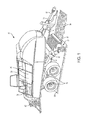
- FIG. 1 is a perspective view of a machine, such as a baler, having a variable-length connector rod in accordance with one implementation of the present disclosure.
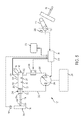
- FIG. 2 is a schematic view of the baler of FIG. 1 illustrating the compression assembly, the pickup assembly, and the controller.
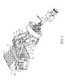
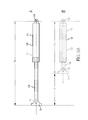
- FIG. 3 is a perspective view of the compression assembly of the baler of FIG. 1 .
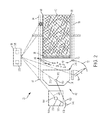
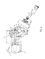
- FIG. 4 is a side view of the compression assembly of the baler of FIG. 1 .
- FIG. 5 is a schematic view of the hydraulic assembly of the baler of FIG. 1 .
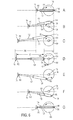
- FIG. 6 illustrates the variable-length connecting rod of FIG. 2 in various positions corresponding to a first stroke profile.
- FIG. 6A illustrates the variable-length connecting rod of FIG. 2 in an extended and retracted configuration.
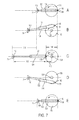
- FIG. 7 illustrates the variable-length connecting rod of FIG. 2 in various positions corresponding to a second stroke profile.
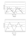
- FIG. 8 is a chart correlating the connecting rod length for a given crank position with respect to the first stroke profile.
- FIG. 9 is a chart correlating the connecting rod length for a given crank position with respect to the second stroke profile.
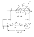
- FIG. 10 illustrates an alternative implementation of the variable-length connecting rod in various positions.
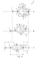
- FIG. 11 illustrates an alternative implementation of the variable-length connecting rod in various positions.
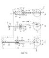
- FIG. 12 illustrates an alternative implementation of the variable-length connecting rod in various positions.
- variable length connecting rods permit the baler to achieve larger compression forces at the plunger face while limiting the forces experienced by the gearbox of the baler.
- the disclosed baler is able to produce denser bales for a given gearbox design.
- the variable length connecting rods permit the baler to increase the plunger throw (described below) for a given crank arm dimension.
- the variable length connecting rods permit the baler to finely tune the reciprocating motion of the plunger, or plunger stroke, with respect to the baling chamber.
- a baler 10 includes a frame 14 , a set of wheels 18 mounted on the frame 14 , a feed system 22 coupled to the frame 14 , a compression system 26 having a plunger assembly 82 ( FIG. 2 ) to receive and compress crop material 54 provided by the feed system 22 , and a controller 38 ( FIGS. 2 and 5 ) to monitor and direct the baling operation.
- the baler 10 is a square baler for forming bales 42 of a crop, such as hay, straw, or other biomasses.
- the frame 14 of the baler 10 includes a tow bar 46 extending from the frame 14 and connectable to a towing vehicle (not shown), such as an agricultural tractor or other vehicle.
- the baler 10 also includes a power takeoff shaft 50 connectable to the towing vehicle to transmit a rotating drive force from the towing vehicle to various components of the baler 10 .
- the baler 10 may have a dedicated power supply and/or prime mover (not shown), such as an engine, motor, battery, fuel cell, etc., for driving the wheels 18 and for driving and/or powering the various components of the baler 10 .
- the feed system 22 of the baler 10 is configured to pick up crop material 54 from a support surface 58 and convey it to the compression system 26 .
- the feed system 22 includes a pickup assembly 62 for receiving the crop material 54 from the support surface 58 , and a delivery assembly 64 for directing the collected crop material 54 to the compression system 26 .
- the pickup assembly 62 includes a roller baffle 66 oriented generally perpendicular to the direction of travel for picking up the crop material 54 and placing it in the baler 10 .
- the delivery assembly 64 of the feed system 22 directs the crop material 54 collected by the pickup assembly 62 to the compression system 26 .
- the delivery assembly 64 is configured to direct a metered amount of crop material 54 into the baling chamber 70 during every stroke of the plunger 74 (described below).
- the delivery assembly 64 is adjustable, permitting different amounts of crop material 54 to be fed into the compression system 26 at a given time (i.e., the “feed rate”).
- the feed system 22 is configured to receive one or more signals from the controller 38 causing it to increase or decrease the amount of crop material 54 being delivered to the compression system 26 on a particular stroke.
- the compression system 26 of the baler 10 includes the baling chamber 70 in communication with the feed system 22 , a bale case 78 at least partially defining the baling chamber 70 , and the plunger assembly 82 positioned at least partially within the baling chamber 70 .
- a metered amount of crop material or flake 54 is positioned within the baling chamber 70 by the feed system 22 whereby the plunger assembly 82 compresses the crop material 54 against already compacted crop material positioned in the bale case 78 , herein referred to as the forming bale 86 .
- the plunger assembly 82 then retracts through the baling chamber 70 as another metered amount of crop material 54 is positioned within the baling chamber 70 by the feed system 22 and the stroke begins again.
- the compression system 26 compresses the newly introduced crop material 54 against the face of the forming bale 86 , causing the forming bale 86 to grow into a densely packed cuboid shape within the bale case 78 .
- the forming bale 86 achieves the desired size and density, it is bound (e.g., by wire) to form the bale 42 .
- the freshly created bale 42 subsequently becomes a support surface against which the next forming bale 86 may begin to form and the process is repeated.
- the bale 42 is ejected from the rear of the baler 10 for subsequent collection.
- the bale case 78 is substantially rectangular in shape having a first open end 90 to receive the plunger 74 therein, and a second open end 94 , opposite the first open end 90 positioned proximate the rear of the baler 10 .
- the bale case 78 acts as a container, holding the forming bale 86 and one or more completed bales 42 against which the compression system 26 compresses the newly introduced crop material 54 from the feed system 22 . While doing so, the bale case 78 applies a compressive or otherwise resistive force against the forming bale 86 and any completed bales 42 to resist motion within the bale case 78 toward the second open end 94 . In particular, it is this resistive force that permits the compressive force of the compression system 26 to compact the crop material 54 within the baling chamber 70 .
- the walls 98 of the bale case 78 are adjustable with respect to one another to vary the amount of resistive force applied to the forming bale 86 and bales 42 .
- the walls 98 of the bale case 78 may move inwardly to apply more pressure to the outside of the forming bale 86 or bale 42 and therefore create a greater resistive force.
- the walls 98 of the bale case 78 may also move outwardly, away from one another, to reduce the pressure on the outside of the forming bale 86 or bale 42 and therefore create less resistive force.
- the greater the resistive force applied to the forming bale 86 and bales 42 the greater the amount of compression that occurs with each stroke of the compression system 26 and the denser the resulting bale 42 .
- the plunger assembly 82 of the compression system 26 includes a gearbox 110 having an output shaft 114 , a pair of crank arms 118 coupled to and rotatable with the output shaft 114 , the plunger 74 movable with respect to the baling chamber 70 , and a pair of variable-length connecting rods 122 each extending between and coupled to both a respective crank arm 118 and the plunger 74 .
- the plunger assembly 82 also includes a hydraulic system 126 ( FIG. 5 ) to at least partially control the length of the connecting rods 122 (i.e., the connector length 162 , described below).
- the gearbox 110 of the plunger assembly 82 receives input from the power takeoff shaft 50 , which in turn is driven by an exterior source, such as a tractor and the like (described above).
- the gearbox 110 may be driven by a stand-alone power system, such as an internal combustion engine.
- the gearbox 110 typically includes a number of gear sets (not shown) to transmit the torque provided by the power takeoff shaft 50 to the output shaft 114 at a given gear ratio.
- the gearbox 110 may have multiple, interchangeable gear sets to permit the gear ratio provided by the gearbox 110 to be changed according to current operating conditions.
- the plunger assembly 82 includes a pair of crank arms 118 positioned on opposite sides of the gearbox 110 and a pair of connecting rods 122 coupled to the crank arms 118 , it is also appreciated that additional crank arms 118 or connecting rods 122 may be present. Still further, a single crank arm 118 and a single connecting rod 122 may be used. In still other implementations, multiple connecting rods 122 may extend from a single crank arm 118 .
- the plunger 74 of the plunger assembly 82 is substantially rectangular in shape and includes compression surface 314 configured to engage flake 54 positioned within the baling chamber 70 , and a fifth mounting point 166 coupled to the fourth mounting point 150 of a respective connecting rod 122 .
- the plunger 74 is positioned within and movable with respect to the baling chamber 70 between an extended position, where the plunger 74 is its furthest distance from the output shaft 114 , and a retracted position, where the plunger 74 is positioned its closest distance to the output shaft 114 .
- the distance between the retracted position and the extended position is defined as the “plunger stroke length 316 .”
- the plunger stroke length 316 is at least partially determined by the crank throw length 144 (described below) and the connector throw length 164 (described below).
- the plunger stroke length 316 at least partially determines the density of the resulting bale 42 and therefore the magnitude of the compression forces applied to the compression surface 314 of the plunger 74 .
- the plunger stroke length 316 is greater than the crank throw length 144 and greater than the connector throw length 164 .
- the plunger 74 is configured to compress crop material 54 located within the baling chamber 70 and positioned between the compression surface 314 and the forming bale 86 .
- the plunger 74 begins each stroke from the retracted position, with a metered amount of crop material or flake 54 positioned within the baling chamber 70 .
- the plunger 74 then moves toward the extended position capturing the newly introduced crop material 54 between itself (i.e., the compression surface 314 ) and the forming bale 86 .
- the flake 54 may be captured between the plunger 74 and the previous bale 42 .
- the moment in which the plunger 74 captures the flake 54 between the compression surface 314 and the forming bale 86 is herein referred to as the “contact point.”
- the plunger 74 continues to move toward the extended position thereby compressing the crop material 54 into the forming bale 86 .
- the plunger 74 begins returning back to the retracted position eventually disengaging from the forming bale 86 and moving away from the bale case 78 .
- the feed system 22 may position a second metered amount of crop material 54 within the baling chamber 70 and the stroke begins anew.
- Each crank arm 118 of the plunger assembly 82 is substantially elongated in shape transferring torque between the output shaft 114 and a respective connecting rod 122 .
- Each crank arm 118 defines a first mounting point 134 and a second mounting point 138 spaced a crank length 142 ( FIG. 6 ) from the first mounting point 134 .
- the first mounting point 134 is coupled to and rotates together with the output shaft 114 of the gearbox 110 while the second mounting point 138 is coupled to a respective connecting rod 122 .
- the first mounting point 134 includes an aperture formed into the crank arm 118 and sized to at least partially receive a portion of the output shaft 114 therein.
- the first mounting point 134 also includes a keyway, splines, and the like causing the output shaft 114 and crank arms 118 to rotate together as a unit.
- each crank arm 118 defines a crank throw length 144 calculated as twice the crank length 142 .
- Each variable-length connecting rod 122 of the plunger assembly 82 is substantially elongated in shape having a third mounting point 146 , and a fourth mounting point 150 spaced a connector length 162 from the third mounting point 146 and movable with respect thereto. More specifically, the third mounting point 146 is movable with respect to the fourth mounting point 150 between an extended position (see Position A of FIG. 6A ), where the connector length 162 is a first length, and a retracted position (see Position B of FIG. 6A ), where the connector length 162 is a second length, less than the first length.
- the difference between the first length (i.e., fully extended) and the second length (i.e., fully retracted) is defined as the connector throw length 164 .
- each connecting rod 122 includes an actuator 124 in the form of a hydraulic cylinder coupled to and extending between the second mounting point 138 of the respective crank arm 118 and the fifth mounting point 166 of the plunger 74 (described below).
- Each actuator 124 includes a cylinder portion 170 of the hydraulic cylinder forms the third mounting point 146 , and a piston portion 174 moveable with respect to the cylinder portion 170 forms the fourth mounting point 150 . ( FIGS. 3 and 4 ). While the illustrated actuator 124 is a hydraulic cylinder, in alternative implementations the actuator 234 ′′ may include a mechanical or pneumatic actuator (not shown).
- the cylinder portion 170 of each actuator 124 is substantially cylindrical in shape including an annular outer wall 182 that at least partially defines an elongated cavity 186 therein.
- the cavity 186 includes a first end 190 proximate the third mounting point 146 , and a second end 194 opposite the first end 190 .
- the cylinder portion 170 also includes a first fluid port 198 in fluid communication with the cavity 186 and positioned proximate the first end 190 thereof.
- the cylinder portion 170 also includes a second fluid port 202 in fluid communication with the cavity 186 and positioned proximate the second end 194 thereof.
- the piston portion 174 of the actuator 124 includes a piston 206 sized to be positioned within and movable axially along the length of the cavity 186 of the cylinder portion 170 between the first end 190 and the second end 194 .
- the piston portion 174 also includes a rod 210 extending axially from the piston 206 , beyond the second end 194 of the cavity 186 , to produce the fourth mounting point 150 .
- the piston 206 of the piston portion 174 contacts and forms a seal with the annular outer wall 182 of the cavity 186 thereby dividing the cavity 186 into a first volume 214 in fluid communication with the first fluid port 198 , and a second volume 218 in fluid communication with the second fluid port 202 .
- each actuator 124 receives hydraulic fluid from the hydraulic system 126 causing the piston portion 174 and the fourth mounting point 150 to move with respect to the cylinder portion 170 and the third mounting point 146 . More specifically, when the actuator 124 receives hydraulic fluid via the first fluid port 198 , fluid flows into the first volume 214 of the cavity 186 causing the first volume 214 to increase in size while fluid is forced out of the second volume 218 causing the second volume 218 to decrease in size. The resulting fluid flow forces the piston 206 toward the second end 194 of the cavity 186 (see Positions A-C of FIG. 6 ) causing the connector length 162 to increase.
- each connecting rod 122 may include linkages, tracks, pulleys, cables, and gearsets, in addition to the actuator 124 (see below).
- the hydraulic system 126 of the plunger assembly 82 includes a pump 290 and a reservoir 294 in fluid communication with the pump 290 .
- the hydraulic system 126 also includes a first feed line 298 extending between and in fluid communication with the pump 290 and the first fluid port 198 of a respective connecting rod 122 , and a second feed line 302 extending between and in fluid communication with the pump 290 and the second fluid port 202 of the same connecting rod 122 .
- the hydraulic system 126 also includes one or more valves (not shown) to direct the output of the pump 290 through either the first feed line 298 and/or the second feed line 302 .
- the pump 290 is a variable displacement pump able to adjust the rate and pressure at which fluid is discharged therefrom.
- the hydraulic system may also include one or more safety valves to direct excess fluid to the reservoir 294 .
- the hydraulic system 126 may also include a lockout valve 306 positioned between and in fluid communication with the first feed line 298 and the first fluid port 198 .
- the lockout valve 306 is adjustable between an unlocked configuration, where the first fluid port 198 is in fluid communication with the pump 290 , and a locked configuration, where the first fluid port 198 is fluidly isolated from the pump 290 .
- the lockout valve 306 is positioned along the length of the first feed line 298 .
- the lockout valve 306 may be formed into the first fluid port 198 or formed integrally with the annular wall 182 of the connecting rod 122 .
- the hydraulic system 126 may include multiple sets of feed lines (i.e., a first feed line 298 and a second feed line 302 ) for each corresponding connecting rod 122 . Still further, the hydraulic system 126 may include a second set of valves (not shown) to permit the hydraulic system 126 to selectively provide fluid to one or more of the connecting rods 122 at any given time. Still further, the hydraulic system 126 may include a plurality of lockout valves 306 to selectively isolate each individual connecting rod 122 .
- the controller 38 of the baler 10 includes a processor 318 , a memory unit 322 in operable communication with the processor 318 , one or more sensors 326 , 330 , 332 sending and receiving signals from the processor 318 , and a user input 334 in operable communication with the processor 318 .
- the processor 318 is also in operable communication with various elements of the hydraulic system 126 including, but not limited to, the pump 290 and one or more valves (not shown).
- the processor 318 receives signals from the one or more sensors 326 , 330 , 332 , combines that information with one or more predetermined control algorithms, and outputs signals to control the motion of the plunger 74 .
- the baler 10 includes a crank arm position sensor 326 , a plunger position sensor 330 , and a pressure transducer 332 .
- the sensors 326 , 330 , 332 may be present individually, in plurality, or in combination.
- the controller 38 may also include additional sensors such as, but not limited to, a connector length sensor (not shown).
- the crank arm position sensor 326 includes a position sensor mounted to a respective crank arm 118 of the plunger assembly 82 and configured to measure the relative position of the crank arm 118 with respect to the gearbox 110 .
- the crank arm position sensor 326 may include a sensor mounted directly to the crank arm 118 , or a sensor mounted on the output shaft 114 .
- Such sensors may include Hall Effect sensors, variable resistance sensors, optical sensors, and the like.
- the plunger position sensor 330 determines the relative position of the plunger 74 with respect to the baling chamber 70 .
- the plunger position sensor 330 may include a sensor mounted directly on the plunger 74 , a sensor mounted to the baling chamber 70 , or a sensor mounted to the output shaft 114 of the gearbox 110 .
- Such sensors may include Hall Effect sensors, variable resistance sensors, optical sensors, and the like.
- the pressure transducer 332 detects the pressure of the hydraulic fluid positioned within the first volume 214 of the cavity 186 of a respective connecting rod 122 . More specifically, the pressure transducer 332 is in fluid communication with the first volume 214 of the cavity 186 . In the illustrated implementation, the pressure transducer 332 is spliced into the first feed line 298 of the hydraulic system 126 . However in alternative implementations, the pressure transducer 332 may be formed into the first fluid port 198 or formed integrally with the annular wall 182 of the connecting rod 122 . Such sensors may include pressure sensors and the like. In still other implementations, the pressure transducer 332 may also be utilized to determine the force applied to the compression surface 314 of the plunger 74 . In such implementations, the processor 318 includes one or more conversion calculations to convert the pressure readings of the pressure transducer 332 into plunger force readings.
- a plurality pressure transducers 332 may be present, each corresponding with a particular connecting rod 122 .
- the processor 318 may take into account the pressure readings from each transducer 332 to calculate an overall or general pressure reading applicable to the total force being applied to the plunger 74 . More specifically, the processor 318 may take into account the pressure readings from each transducer 332 by taking the average thereof, combining the readings together, or placing each reading within a predetermined algorithm. Furthermore, the processor 318 may also calculate a local pressure reading by taking into account a subset of pressure transducers 332 corresponding to a subset of connecting rods 122 .
- the processor 318 may calculate the total force applied to the plunger 74 by utilizing the signals provided by both pressure transducers 332 . Furthermore, the processor 318 may calculate the localized force being applied to a first location of the plunger 74 by only taking into account the pressure transducer 332 corresponding with the connecting rod 122 coupled to the plunger 74 proximate the first location. Still further, the processor 318 may calculate the localized force being applied to a second location of the plunger 74 by only taking into account the pressure transducer 332 corresponding with the connecting rod 122 coupled to the plunger 74 proximate the second location.
- the processor 318 of the baler 10 monitors the motion of the plunger 74 and the crank arm 118 and outputs signals to the hydraulic system 126 to control the extension and contraction of the connecting rod 122 to produce the desired plunger motion or “stroke profile.” More specifically, the processor 318 outputs signals to the pump 290 and valves (not shown) of the hydraulic system 126 to direct the flow of hydraulic fluid toward either the first fluid port 198 or the second fluid port 202 . As the plunger 74 moves along its stroke path, the processor 318 receives a stream of information in the form of signals from the sensors 326 , 330 , 332 positioned throughout the baler 10 .
- the processor 318 may receive data including, but not limited to, the position of the plunger 74 , the rotational position of the crank arm 118 (i.e., the crank position), the connector length 162 , the pressure of the hydraulic fluid, and the like. The processor 318 then compiles the raw information received from the sensors 326 , 330 , 332 and processes it to determine the desired connector length 162 as the stroke progresses.
- each stroke profile may include various quantities and combinations of different stages or steps to produce the desired stroke profile.
- each stroke profile may include an extension stage 338 , a locking stage 340 , a locked compression stage 346 , an unlocking stage 350 , and a retraction stage 354 .
- the timing, frequency, and duration of the various stages are generally dependent upon the relative location of the crank arm 118 or “crank position.”
- the crank position is defined as an axis extending radially outwardly from the first mounting point 134 through the second mounting point 138 .
- the 3 o'clock crank position (Position A of FIG.
- the timing, frequency, and duration of the various stages may also be dependent upon the position of the plunger 74 , the forces exerted on the plunger 74 , the connector length 162 , the hydraulic fluid pressure levels, and the like.
- a first stroke profile begins with the crank arm 118 in the 3 o'clock position, the connecting rod 122 in the retracted position, and the plunger 74 in the retracted position (Position A of FIG. 6 ).
- the crank arm 118 travels in a counter-clockwise direction at a relatively constant rotational speed. In alternative implementations, the rotational speed and direction of the crank arm 118 may be adjusted as necessary.
- the processor 318 monitors and controls the extension stage 338 when the crank arm 118 is in the 3 o'clock position (Position A of FIG. 6 ).
- the processor 318 sends signals to the hydraulic system 126 instructing the pump 290 to direct hydraulic fluid via the first feed line 298 to the first fluid port 198 .
- this causes the third mounting point 146 to move away from the fourth mounting point 150 and the connector length 162 of the connecting rod 122 to increase.
- the connector length 162 continues to increase throughout the duration of the extension stage 338 ( FIG. 8 ) at a speed generally dictated by the rate at which the pump 290 is providing fluid to the first volume 214 .
- the motion of the plunger 74 during the extension stage 338 is determined by a combination of the speed of the rotation of the crank arm 118 (i.e., with the second mounting point 138 moving toward the first open end 90 of the bale case 78 ) and the speed at which the connector length 162 is increasing.
- the extension stage 338 continues until the crank arm 118 reaches the 10 o'clock position (Position C of FIG. 6 ). In alternative implementations, the extension stage 338 lasts until the crank arm 118 reaches between approximately the 12 o'clock position and approximately the 10 o'clock position. In still other implementations, the processor 318 may remain in the extension stage 338 until the contact point (described above) is reached. In still other implementations, the processor 318 may remain in the extension stage 338 until the connector length 162 reaches a predetermined value. In still other implementations, the processor 318 may remain in the extension stage until the fluid pressure within the first volume 214 rises above a predetermined value. In still other implementations, the duration of the extension stage 338 may take into consideration a combination of the factors listed above.
- the processor 318 enters the locking stage 340 (Position C of FIG. 6 ).
- the processor 318 sends a signal to the lockout valve 306 causing it to switch from the unlocked configuration to the locked configuration.
- the first volume 214 of the connecting rod 122 becomes fluidly isolated from the hydraulic system 126 .
- the lockout valve 306 has effectively “trapped” any hydraulic fluid contained within the first volume 214 therein.
- the incompressible nature of the hydraulic fluid within the first volume 214 causes the connecting rod 122 to effectively become rigid and restricts any relative movement between the third mounting point 146 and the fourth mounting point 150 .
- the locking stage 340 occurs almost instantaneously (i.e., while the crank arm 118 is in Position C of FIG. 6 ).
- the locking stage 340 also serves to isolate any pressure exerted onto the connecting rod 122 from the hydraulic system 126 .
- the hydraulic system 126 need only have the capacity to withstand and produce the hydraulic pressures necessary to extend and retract the connecting rod 122 without any significant resistance.
- the hydraulic system 126 does not need to withstand or produce the pressures necessary for compression of the flake 54 positioned within the baling chamber 70 .
- the processor 318 In addition to locking the lockout valve 306 , the processor 318 also sends signals to the pump 290 and valves of the hydraulic system 126 instructing them to stop providing fluid to the first fluid port 198 of the connecting rod 122 . In instances where residual fluid flow exists (i.e., due to the coasting of the pump 290 and the like), one or more over-pressure valves (not shown) may be positioned between the pump 290 and the lockout valve 306 to bleed off pressure and direct excess fluid into the reservoir 294 .
- the processor 318 enters the locked compression stage 346 (Positions C-E of FIG. 6 ).
- the connector length 162 remains fixed ( FIG. 8 ).
- the compression surface 314 of the plunger 74 traps the flake 54 between itself and the forming bale 86 and applies the necessary pressure to compress the flake 54 into the forming bale 86 .
- the fluid pressure within the first volume 214 increases as the pressure exerted by the compression surface 314 against the flake 54 and forming bale 86 increases.
- the compression stage 346 continues until the crank arm 118 reaches the 7 o'clock position (Position E of FIG. 6 ).
- the processor 318 remains in the compression stage 346 until the crank arm 118 reaches approximately the 9 o'clock position to approximately the 7 o'clock position.
- the processor 318 remains in the compression stage 346 until the pressure applied to the compression surface 314 of the plunger 74 drops below a predetermined value.
- the processor 318 may calculate the pressure value based at least in part on the signals sent from the pressure transducer 332 .
- the processor 318 remains in the compression stage 346 until the pressure within the first volume 214 falls below a predetermined level as determined by the pressure transducer 332 . In still other implementations, the processor 318 remains in the compression stage 346 until the plunger 74 disengages from the forming bale 86 . In still other implementations, the processor 318 remains in the compression stage 346 until the plunger 74 is in a predetermined position. In still other implementations, the duration of the compression stage 346 may be influenced by a combination of the factors listed above.
- the processor 318 After the compression stage 346 , the processor 318 begins the unlocking stage 350 . During the unlocking stage 350 the processor 318 sends a signal to the lockout valve 306 causing it to switch from the locked configuration to the unlocked configuration. By doing so, fluid communication between the first volume 214 and the hydraulic system 126 is restored and the third mounting point 146 is able to move with respect to the fourth mounting point 150 . In the illustrated implementation, the unlocking stage 350 occurs almost instantaneously.
- the processor enters the retraction stage 354 (Positions E-G of FIG. 6 ).
- the processor 318 sends signals to the hydraulic system 126 instructing the pump 290 to direct hydraulic fluid via the second feed line 302 to the second fluid port 202 .
- this causes the third mounting point 146 to move toward the fourth mounting point 150 and the connector length 162 of the connecting rod 122 to decrease.
- the connector length 162 continues to decrease throughout the duration of the retraction stage 354 ( FIG. 8 ) at a speed generally dictated by the rate at which the pump 290 is providing fluid to the second volume 218 .
- the motion of the plunger 74 during the retraction stage 354 is determined by the speed of the rotation of the crank arm 118 in a counter-clockwise direction (i.e., with the second mounting point 138 moving away from the first open end 90 of the bale case 78 ) and the speed at which the connector length 162 is decreasing.
- the retraction stage 354 continues until the crank arm 118 returns to the 3 o'clock position (Position G of FIG. 6 ) at which time the processor 318 switches to the extension stage 338 and the process begins anew ( FIG. 8 ).
- the processor 318 remains in the retraction stage 354 until the connector length 162 reaches a predetermined value.
- the processor 318 remains in the retraction stage 354 based on a combination of the above described factors.
- a second stroke profile begins with the crank arm 118 in the 3 o'clock position, the connecting rod 122 in the retracted position, and the plunger 74 in the retracted position (Position A of FIG. 7 ).
- the crank arm 118 travels in a counter-clockwise direction at a relatively constant rotational speed.
- the rotational speed and direction of the crank arm 118 may be adjustable.
- the processor 318 With the crank arm 118 in the 3 o'clock position, the processor 318 enters the extension stage 338 (Positions A-C of FIG. 7 ). During the extension stage 338 , the processor 318 sends signals to the hydraulic system 126 instructing the pump 290 to direct hydraulic fluid via the first feed line 298 to the first fluid port 198 . As described above, this causes the connector length 162 of the connecting rod 122 to increase. The connector length 162 continues to increase throughout the duration of the extension stage 338 ( FIG. 9 ) at a speed generally dictated by the rate at which the pump 290 is providing fluid to the first volume 214 .
- the motion of the plunger 74 during the extension stage 338 is determined by a combination of the speed of the rotation of the crank arm 118 (i.e., with the second mounting point 138 moving toward the first open end 90 of the bale case 78 ) and the speed at which the connector length 162 is increasing.
- the second stroke profile remains in the extension stage beyond the contact point and until the crank arm 118 reaches the 9 o'clock position (Position C of FIG. 7 ).
- the compression force applied by the plunger 74 is provided by the movement of the crank arm 118 and the hydraulic system 126 . Therefore, the pump 290 and first feed line 298 must be of sufficient durability to withstand the pressures exerted during the compression stage. With that said, given that the processor 318 is in the extension stage 338 over a longer range of the crank arm 118 rotation, a larger plunger stroke length 316 can be produced for a given crank arm 118 rotation speed.
- the processor 318 enters the retraction stage 354 (Positions C-E of FIG. 7 ).
- the processor 318 sends signals to the hydraulic system 126 instructing the pump 290 to direct hydraulic fluid via the second feed line 302 to the second fluid port 202 .
- this causes the third mounting point 146 to move toward the fourth mounting point 150 and the connector length 162 of the connecting rod 122 to decrease.
- the connector length 162 continues to decrease throughout the duration of the retraction stage 354 ( FIG. 9 ) at a speed generally dictated by the rate at which the pump 290 is providing fluid to the second volume 218 .
- the motion of the plunger 74 during the retraction stage 354 is determined by the speed of the rotation of the crank arm 118 in a counter-clockwise direction (i.e., with the second mounting point 138 moving away from the first open end 90 of the bale case 78 ) and the speed at which the connector length 162 is decreasing.
- first and second stroke profiles are described assuming the hydraulic system 126 provides similar quantities of fluid to both connecting rods 122 , it is appreciated that in alternative implementations the hydraulic system 126 may provide different quantities of fluid to each individual connecting rod 122 .
- the processor 318 is able to adjust the horizontal orientation of the compression surface 314 with respect to the baling chamber 70 .
- providing the similar levels of fluid to both connecting rods 122 cause the orientation of the compression surface 314 to remain unchanged.
- FIG. 10 illustrates an alternative implementation of a connecting rod 122 ′.
- the connecting rod 122 ′ is substantially similar to the connecting rod 122 illustrated in FIGS. 3-4 and 6-7 except for those elements described herein.
- the connecting rod 122 ′ includes a first link 222 ′ including the third mounting point 146 ′, a second link 226 ′ pivotably coupled to the first link 222 ′ opposite the third mounting point 146 ′ and including the fourth mounting point 150 ′.
- the first and second links 222 ′, 226 ′ form a first angle 230 ′ therebetween which in turn generally dictates the distance between the third mounting point 146 ′ and the fourth mounting point 150 ′ (i.e., at least partially defines the connector length 162 ′).
- the larger the first angle 230 ′ (up to 180 degrees), the greater the connector length 162 ′.
- the smaller the first angle 230 ′ the smaller the connector length 162 ′ (compare Position B to Position A in FIG. 10 ).
- the connecting rod 122 ′ also includes an actuator 234 ′ positioned between and coupled to both the first link 222 ′ and the second link 226 ′.
- the actuator 234 ′ includes a first end 238 ′ coupled to the first link 222 ′, and a second end 242 ′ coupled to the second link 226 ′.
- the length of the actuator 234 ′ (herein defined as the distance between the first end 238 ′ and the second end 242 ′) is adjustable causing the first angle 230 ′ between the links 222 ′, 224 ′ to change and, as described above, the connector length 162 ′ to vary.
- connecting rod 122 ′ is configured such that when the actuator 234 ′ increases in length, the first angle 230 ′ and the connector length 162 ′ increases (Position B of FIG. 10 ). In contrast, when the actuator 234 ′ decreases in length, the first angle 230 ′ and the connector length 162 ′ decreases (Position A of FIG. 10 ).
- the actuator 234 ′ includes a hydraulic cylinder in operable communication with the hydraulic system 126 and similarly configured as with the connecting rod 122 described above. In alternative implementations, however, electric and pneumatic actuators (not shown) may instead be used. In still other implementations, the actuator's orientation may be flipped.
- first and the second ends 238 ′, 242 ′ of the actuator 234 ′ are coupled to their respective links 222 ′, 224 ′ proximate the link's center.
- a given change in length of the actuator 234 ′ results in a larger change in the connector length 162 .
- the mounting locations of the first and second ends 238 ′, 242 ′ may be modified with respect to the third and fourth mounting points 146 ′, 150 ′ to adjust the mechanical advantage provided by the links 222 ′, 224 ′.
- FIG. 11 illustrates another alternative implementation of a connecting rod 122 ′′.
- the connecting rod 122 ′′ is substantially similar to the connecting rod 122 ′ illustrated in FIG. 10 except for the elements described herein.
- the connecting rod 122 ′′ includes a linkage assembly 246 ′′ formed from four individual links 250 a ′′, 250 b ′′, 250 c ′′, and 250 d ′′ coupled together with a plurality of pins 254 a ′′, 254 b ′′, 254 c ′′, and 254 d ′′ to form a parallelogram shape.
- pin 254 a ′′ forms the third mounting point 146 ′′
- pin 254 c ′′ forms the fourth mounting point 150 ′′.
- each link 250 a ′′, 250 b ′′, 250 c ′′, and 250 d ′′ is able to pivot with respect to all adjacent links causing the distance between opposing pins to change. More specifically, each change in distance between opposing pins causes a reactionary change in distance between the alternative pair of opposing pins. For example, shortening the distance between pins 254 b ′′ and 254 d ′′ results in an increase in distance between pins 254 a ′′ and 254 c ′′. (Compare Position A to Position C in FIG. 11 ). In the illustrated implementation, all four links 250 a ′′, 250 b ′′, 250 c ′′, and 250 d ′′ are equal in length; however in alternative implementations, the relative size of each link may be altered to provide the desired geometric configuration.
- the connecting rod 122 ′′ also includes an actuator 234 ′′ extending between and coupled to the linkage assembly 246 ′′.
- the actuator 234 ′′ includes a first end 238 ′′ coupled to pin 254 b ′′, and a second end 242 ′′ coupled to pin 254 d ′′.
- the actuator 234 ′′ is a hydraulic cylinder in operable communication with the hydraulic system 126 similar to the connecting rod 122 .
- the actuator 234 ′′ may include a mechanical or pneumatic actuator (not shown). In still other implementations, the actuator's orientation may be flipped.
- the length of the actuator 234 ′′ (i.e., the distance between the first end 238 ′′ and the second end 242 ′′) is adjustable causing the distance between pins 254 b ′′ and 254 d ′′ to vary. Therefore, increasing the length of the actuator 234 ′′ causes the distance between pins 254 b ′′ and 254 d ′′ to increase. This increase in length causes the distance between pin 254 a ′′ (i.e., the third mounting point 146 ′′) and pin 254 c ′′ (i.e., the fourth mounting point 150 ′′) to decrease. (See Position A of FIG. 11 ). As such, the connector length 162 ′′ decreases.
- decreasing the length of the actuator 234 ′′ causes the distance between pins 254 b ′′ and 254 d ′′ to decreases which results in the distance between pin 254 a ′′ and pin 254 c ′′ to increase. (See Position C of FIG. 11 ). As such, the connector length 162 ′′ increases.
- FIG. 12 illustrates another alternative implementation of the connecting rod 122 ′′′.
- the connecting rod 122 ′′′ includes a first link 258 ′′′ forming the third mounting point 146 ′, a gear assembly 262 ′ coupled to the first link 258 ′′′ opposite the third mounting point 146 ′, and a second link 266 ′ in operable communication with the gear assembly 262 ′ and forming the fourth mounting point 150 ′′′.
- the connecting rod 122 ′′′ also includes a pair of tracks 270 ′ fixedly mounted with respect to the frame 14 of the baler 10 and forming a plurality of gear teeth thereon (not shown).
- the gear assembly 262 ′′′ of the connecting rod 122 ′′′ includes a carriage 274 ′′′ coupled to the first link 258 ′′′, and a pair of gears 278 ′′′ pivotably mounted to the carriage 274 ′′′.
- the carriage 274 ′′′ is coupled to the first link 258 ′′′ opposite the third mounting point 146 ′′′.
- the gears 278 ′′′ operatively engage the teeth (not shown) of the tracks 270 ′′′. As such, any movement of the carriage 274 ′′′ along the length of the tracks 270 ′′′ causes the gears 278 ′′′ to rotate with respect to the carriage 274 ′′′.
- the second link 266 ′′′ of the connecting rod 122 ′′′ is substantially elongated in shape having a first end 282 ′′′ forming the fourth mounting point 150 ′′′, and a second end 286 ′′′ opposite the first end 282 ′′′ defining a plurality of gear teeth (not shown).
- the gear teeth of the second link 266 ′′′ engage both gears 278 ′′′ of the gear assembly 262 ′′′.
- the motion of the carriage 274 ′′′ with respect to the tracks 270 ′′′ and the motion of the second link 266 ′′′ with respect to the carriage 274 ′′′ results in the fourth mounting point 150 ′′′ moving away from the third mounting point 146 ′′′ a distance that is greater than the crank throw length 144 of the crank arm 118 .
- the upper gear 278 ′′′ rotates in a counter-clockwise direction while the lower gear 278 ′′′ rotates in a clockwise direction.
- the rotation of the gears 278 ′′′ causes the second link 266 ′′′ to move in direction B with respect to the carriage 274 ′′′.
Landscapes
- Life Sciences & Earth Sciences (AREA)
- Environmental Sciences (AREA)
- Control Of Fluid Gearings (AREA)
- Hydraulic Motors (AREA)
- Fluid-Pressure Circuits (AREA)
- Details Of Reciprocating Pumps (AREA)
Abstract
Description
- The present disclosure relates to an agricultural baler having a compression system for forming bales of crop.
- Large square balers have been used for harvesting hay for many years. Their primary advantage over other types of balers is that they densify the crop into large rectangular-shaped bales that minimizes both shipping and storage costs. Currently, there is a desire to create bales with higher density, which requires higher plunger forces and thus higher loads on the elements of the drive train (i.e., the connecting rod, gearbox, crank arm, and the like). As such, current baler designs require increasingly more expensive components in the drive train to allow for such large plunger forces.
- In one aspect, the disclosure provides a baler including a frame, a feed system coupled to the frame, a baling chamber, a gearbox, a crank arm driven by the gearbox, a plunger at least partially positioned within and reciprocally movable with respect to the baling chamber, and a connecting rod extending between and coupled to both the crank arm and the plunger, where the connecting rod defines a connector length, and where the connecting rod defines a fluid volume therein. The baler also includes a hydraulic system in operable communication with the connecting rod including a pump, a first feed line extending between and in fluid communication with the fluid volume of the connecting rod and the pump, and a lockout valve adjustable between a first configuration in which the fluid volume is in fluid communication with the pump, and a second configuration in which the fluid volume is not in fluid communication with the pump.
- In another aspect, the disclosure provides a baler including a frame, a feed system coupled to the frame, a baling chamber, a gearbox, a crank arm driven by the gearbox, a plunger at least partially positioned within and reciprocally movable with respect to the baling chamber, and a connecting rod extending between and coupled to both the crank arm and the plunger, where the connecting rod defines a connector length, and where the connecting rod defines a fluid volume therein. The baler also includes a hydraulic system in fluid communication with the fluid volume, the hydraulic system having a hydraulic pump, and wherein the hydraulic system is adjustable between a first configuration, in which the hydraulic pump is fluidly isolated from the fluid volume of the connecting rod, and a second configuration, in which the hydraulic pump is in fluid communication with the fluid volume of the connecting rod.
- In yet another aspect, the disclosure provides a baler including a frame, a feed system coupled to the frame, a baling chamber, a gearbox, a plunger at least partially positioned within and reciprocally movable with respect to the baling chamber, and a connecting rod extending between and coupled to both the crank arm and the plunger, where the connecting rod defines a connector length, and where the connecting rod further defines a first fluid volume and a second fluid volume therein. The baler also includes a hydraulic system in fluid communication with the first fluid volume and the second fluid volume of the connecting rod, the hydraulic system including a hydraulic pump, and where the hydraulic system is adjustable between an extension stage in which the hydraulic pump provides fluid to the first fluid volume of the connecting rod, a locked stage in which the hydraulic pump is fluidly isolated from at least one of the first fluid volume and the second fluid volume of the connecting rod, and a retraction stage in which the hydraulic pump provides fluid to the second fluid volume of the connecting rod.
- Other aspects of the disclosure will become apparent by consideration of the detailed description and accompanying drawings.
-
FIG. 1 is a perspective view of a machine, such as a baler, having a variable-length connector rod in accordance with one implementation of the present disclosure. -
FIG. 2 is a schematic view of the baler ofFIG. 1 illustrating the compression assembly, the pickup assembly, and the controller. -
FIG. 3 is a perspective view of the compression assembly of the baler ofFIG. 1 . -
FIG. 4 is a side view of the compression assembly of the baler ofFIG. 1 . -
FIG. 5 is a schematic view of the hydraulic assembly of the baler ofFIG. 1 . -
FIG. 6 illustrates the variable-length connecting rod ofFIG. 2 in various positions corresponding to a first stroke profile. -
FIG. 6A illustrates the variable-length connecting rod ofFIG. 2 in an extended and retracted configuration. -
FIG. 7 illustrates the variable-length connecting rod ofFIG. 2 in various positions corresponding to a second stroke profile. -
FIG. 8 is a chart correlating the connecting rod length for a given crank position with respect to the first stroke profile. -
FIG. 9 is a chart correlating the connecting rod length for a given crank position with respect to the second stroke profile. -
FIG. 10 illustrates an alternative implementation of the variable-length connecting rod in various positions. -
FIG. 11 illustrates an alternative implementation of the variable-length connecting rod in various positions. -
FIG. 12 illustrates an alternative implementation of the variable-length connecting rod in various positions. - Before any embodiments of the disclosure are explained in detail, it is to be understood that the disclosure is not limited in its application to the details of the formation and arrangement of components set forth in the following description or illustrated in the accompanying drawings. The disclosure is capable of supporting other implementations and of being practiced or of being carried out in various ways.
- The disclosure relates to a baler, and more particularly to baler having one or more variable length connecting rods. More specifically, the variable length connecting rods permit the baler to achieve larger compression forces at the plunger face while limiting the forces experienced by the gearbox of the baler. As such, the disclosed baler is able to produce denser bales for a given gearbox design. Furthermore, the variable length connecting rods permit the baler to increase the plunger throw (described below) for a given crank arm dimension. Still further, the variable length connecting rods permit the baler to finely tune the reciprocating motion of the plunger, or plunger stroke, with respect to the baling chamber.
- Referring to
FIG. 1 , abaler 10 includes aframe 14, a set ofwheels 18 mounted on theframe 14, afeed system 22 coupled to theframe 14, acompression system 26 having a plunger assembly 82 (FIG. 2 ) to receive and compresscrop material 54 provided by thefeed system 22, and a controller 38 (FIGS. 2 and 5 ) to monitor and direct the baling operation. In the illustrated implementation, thebaler 10 is a square baler for formingbales 42 of a crop, such as hay, straw, or other biomasses. - In the illustrated embodiment, the
frame 14 of thebaler 10 includes atow bar 46 extending from theframe 14 and connectable to a towing vehicle (not shown), such as an agricultural tractor or other vehicle. Thebaler 10 also includes apower takeoff shaft 50 connectable to the towing vehicle to transmit a rotating drive force from the towing vehicle to various components of thebaler 10. In other implementations, thebaler 10 may have a dedicated power supply and/or prime mover (not shown), such as an engine, motor, battery, fuel cell, etc., for driving thewheels 18 and for driving and/or powering the various components of thebaler 10. - As shown in
FIGS. 1 and 2 , thefeed system 22 of thebaler 10 is configured to pick upcrop material 54 from asupport surface 58 and convey it to thecompression system 26. In the illustrated implementation, thefeed system 22 includes a pickup assembly 62 for receiving thecrop material 54 from thesupport surface 58, and adelivery assembly 64 for directing the collectedcrop material 54 to thecompression system 26. The pickup assembly 62 includes a roller baffle 66 oriented generally perpendicular to the direction of travel for picking up thecrop material 54 and placing it in thebaler 10. - The
delivery assembly 64 of thefeed system 22 directs thecrop material 54 collected by the pickup assembly 62 to thecompression system 26. In particular, thedelivery assembly 64 is configured to direct a metered amount ofcrop material 54 into thebaling chamber 70 during every stroke of the plunger 74 (described below). In the illustrated implementation, thedelivery assembly 64 is adjustable, permitting different amounts ofcrop material 54 to be fed into thecompression system 26 at a given time (i.e., the “feed rate”). In particular, thefeed system 22 is configured to receive one or more signals from thecontroller 38 causing it to increase or decrease the amount ofcrop material 54 being delivered to thecompression system 26 on a particular stroke. - Illustrated in
FIG. 2 , thecompression system 26 of thebaler 10 includes thebaling chamber 70 in communication with thefeed system 22, abale case 78 at least partially defining thebaling chamber 70, and theplunger assembly 82 positioned at least partially within thebaling chamber 70. During operation, a metered amount of crop material orflake 54 is positioned within thebaling chamber 70 by thefeed system 22 whereby theplunger assembly 82 compresses thecrop material 54 against already compacted crop material positioned in thebale case 78, herein referred to as the formingbale 86. Theplunger assembly 82 then retracts through thebaling chamber 70 as another metered amount ofcrop material 54 is positioned within thebaling chamber 70 by thefeed system 22 and the stroke begins again. With each passing stroke, thecompression system 26 compresses the newly introducedcrop material 54 against the face of the formingbale 86, causing the formingbale 86 to grow into a densely packed cuboid shape within thebale case 78. Once the formingbale 86 achieves the desired size and density, it is bound (e.g., by wire) to form thebale 42. The freshly createdbale 42 subsequently becomes a support surface against which the next formingbale 86 may begin to form and the process is repeated. Once abale 42 is completely formed, thebale 42 is ejected from the rear of thebaler 10 for subsequent collection. - The
bale case 78 is substantially rectangular in shape having a firstopen end 90 to receive theplunger 74 therein, and a secondopen end 94, opposite the firstopen end 90 positioned proximate the rear of thebaler 10. During use, thebale case 78 acts as a container, holding the formingbale 86 and one or more completedbales 42 against which thecompression system 26 compresses the newly introducedcrop material 54 from thefeed system 22. While doing so, thebale case 78 applies a compressive or otherwise resistive force against the formingbale 86 and any completedbales 42 to resist motion within thebale case 78 toward the secondopen end 94. In particular, it is this resistive force that permits the compressive force of thecompression system 26 to compact thecrop material 54 within thebaling chamber 70. - The
walls 98 of thebale case 78 are adjustable with respect to one another to vary the amount of resistive force applied to the formingbale 86 andbales 42. Specifically, thewalls 98 of thebale case 78 may move inwardly to apply more pressure to the outside of the formingbale 86 orbale 42 and therefore create a greater resistive force. Thewalls 98 of thebale case 78 may also move outwardly, away from one another, to reduce the pressure on the outside of the formingbale 86 orbale 42 and therefore create less resistive force. Generally speaking, the greater the resistive force applied to the formingbale 86 andbales 42, the greater the amount of compression that occurs with each stroke of thecompression system 26 and the denser the resultingbale 42. - Referring now to
FIGS. 2-4 , theplunger assembly 82 of thecompression system 26 includes agearbox 110 having anoutput shaft 114, a pair ofcrank arms 118 coupled to and rotatable with theoutput shaft 114, theplunger 74 movable with respect to thebaling chamber 70, and a pair of variable-length connecting rods 122 each extending between and coupled to both arespective crank arm 118 and theplunger 74. Theplunger assembly 82 also includes a hydraulic system 126 (FIG. 5 ) to at least partially control the length of the connecting rods 122 (i.e., theconnector length 162, described below). In the illustrated embodiment, thegearbox 110 of theplunger assembly 82 receives input from thepower takeoff shaft 50, which in turn is driven by an exterior source, such as a tractor and the like (described above). In alternative implementations, thegearbox 110 may be driven by a stand-alone power system, such as an internal combustion engine. Thegearbox 110 typically includes a number of gear sets (not shown) to transmit the torque provided by thepower takeoff shaft 50 to theoutput shaft 114 at a given gear ratio. In some implementations, thegearbox 110 may have multiple, interchangeable gear sets to permit the gear ratio provided by thegearbox 110 to be changed according to current operating conditions. While the illustrated implementation of theplunger assembly 82 includes a pair of crankarms 118 positioned on opposite sides of thegearbox 110 and a pair of connectingrods 122 coupled to the crankarms 118, it is also appreciated that additional crankarms 118 or connectingrods 122 may be present. Still further, asingle crank arm 118 and a single connectingrod 122 may be used. In still other implementations, multiple connectingrods 122 may extend from asingle crank arm 118. - The
plunger 74 of theplunger assembly 82 is substantially rectangular in shape and includescompression surface 314 configured to engageflake 54 positioned within the balingchamber 70, and afifth mounting point 166 coupled to thefourth mounting point 150 of a respective connectingrod 122. During use, theplunger 74 is positioned within and movable with respect to the balingchamber 70 between an extended position, where theplunger 74 is its furthest distance from theoutput shaft 114, and a retracted position, where theplunger 74 is positioned its closest distance to theoutput shaft 114. For the purposes of this application, the distance between the retracted position and the extended position is defined as the “plunger stroke length 316.” In the illustrate implementation, theplunger stroke length 316 is at least partially determined by the crank throw length 144 (described below) and the connector throw length 164 (described below). During the baling process, theplunger stroke length 316 at least partially determines the density of the resultingbale 42 and therefore the magnitude of the compression forces applied to thecompression surface 314 of theplunger 74. In the illustrated implementation, theplunger stroke length 316 is greater than thecrank throw length 144 and greater than theconnector throw length 164. - During the baling process, the
plunger 74 is configured to compresscrop material 54 located within the balingchamber 70 and positioned between thecompression surface 314 and the formingbale 86. In particular, theplunger 74 begins each stroke from the retracted position, with a metered amount of crop material orflake 54 positioned within the balingchamber 70. Theplunger 74 then moves toward the extended position capturing the newly introducedcrop material 54 between itself (i.e., the compression surface 314) and the formingbale 86. In instances where aprevious bale 42 has just been formed and no formingbale 86 has yet been started, theflake 54 may be captured between theplunger 74 and theprevious bale 42. The moment in which theplunger 74 captures theflake 54 between thecompression surface 314 and the forming bale 86 (e.g., makes initial contact with the formingbale 86 or previous bale 42) is herein referred to as the “contact point.” - After the contact point, the
plunger 74 continues to move toward the extended position thereby compressing thecrop material 54 into the formingbale 86. After reaching the extended position, theplunger 74 begins returning back to the retracted position eventually disengaging from the formingbale 86 and moving away from thebale case 78. Once theplunger 74 has returned to its initial retracted position, thefeed system 22 may position a second metered amount ofcrop material 54 within the balingchamber 70 and the stroke begins anew. - Each crank
arm 118 of theplunger assembly 82 is substantially elongated in shape transferring torque between theoutput shaft 114 and a respective connectingrod 122. Each crankarm 118 defines afirst mounting point 134 and asecond mounting point 138 spaced a crank length 142 (FIG. 6 ) from thefirst mounting point 134. When assembled, thefirst mounting point 134 is coupled to and rotates together with theoutput shaft 114 of thegearbox 110 while thesecond mounting point 138 is coupled to a respective connectingrod 122. In the illustrated implementation, thefirst mounting point 134 includes an aperture formed into thecrank arm 118 and sized to at least partially receive a portion of theoutput shaft 114 therein. Thefirst mounting point 134 also includes a keyway, splines, and the like causing theoutput shaft 114 and crankarms 118 to rotate together as a unit. In the present application, each crankarm 118 defines acrank throw length 144 calculated as twice thecrank length 142. - Each variable-
length connecting rod 122 of theplunger assembly 82 is substantially elongated in shape having athird mounting point 146, and afourth mounting point 150 spaced aconnector length 162 from thethird mounting point 146 and movable with respect thereto. More specifically, thethird mounting point 146 is movable with respect to thefourth mounting point 150 between an extended position (see Position A ofFIG. 6A ), where theconnector length 162 is a first length, and a retracted position (see Position B ofFIG. 6A ), where theconnector length 162 is a second length, less than the first length. For the purposes of this application, the difference between the first length (i.e., fully extended) and the second length (i.e., fully retracted) is defined as theconnector throw length 164. - In the illustrated implementation, each connecting
rod 122 includes anactuator 124 in the form of a hydraulic cylinder coupled to and extending between thesecond mounting point 138 of the respective crankarm 118 and thefifth mounting point 166 of the plunger 74 (described below). Eachactuator 124 includes acylinder portion 170 of the hydraulic cylinder forms thethird mounting point 146, and apiston portion 174 moveable with respect to thecylinder portion 170 forms thefourth mounting point 150. (FIGS. 3 and 4 ). While the illustratedactuator 124 is a hydraulic cylinder, in alternative implementations theactuator 234″ may include a mechanical or pneumatic actuator (not shown). - With reference to
FIG. 5 , thecylinder portion 170 of each actuator 124 is substantially cylindrical in shape including an annularouter wall 182 that at least partially defines anelongated cavity 186 therein. Thecavity 186, in turn, includes afirst end 190 proximate thethird mounting point 146, and asecond end 194 opposite thefirst end 190. Thecylinder portion 170 also includes a firstfluid port 198 in fluid communication with thecavity 186 and positioned proximate thefirst end 190 thereof. Thecylinder portion 170 also includes a secondfluid port 202 in fluid communication with thecavity 186 and positioned proximate thesecond end 194 thereof. - As shown in
FIG. 5 , thepiston portion 174 of theactuator 124 includes apiston 206 sized to be positioned within and movable axially along the length of thecavity 186 of thecylinder portion 170 between thefirst end 190 and thesecond end 194. Thepiston portion 174 also includes arod 210 extending axially from thepiston 206, beyond thesecond end 194 of thecavity 186, to produce thefourth mounting point 150. When theactuator 124 is assembled, thepiston 206 of thepiston portion 174 contacts and forms a seal with the annularouter wall 182 of thecavity 186 thereby dividing thecavity 186 into afirst volume 214 in fluid communication with the firstfluid port 198, and asecond volume 218 in fluid communication with the secondfluid port 202. - During use, each
actuator 124 receives hydraulic fluid from thehydraulic system 126 causing thepiston portion 174 and thefourth mounting point 150 to move with respect to thecylinder portion 170 and thethird mounting point 146. More specifically, when theactuator 124 receives hydraulic fluid via the firstfluid port 198, fluid flows into thefirst volume 214 of thecavity 186 causing thefirst volume 214 to increase in size while fluid is forced out of thesecond volume 218 causing thesecond volume 218 to decrease in size. The resulting fluid flow forces thepiston 206 toward thesecond end 194 of the cavity 186 (see Positions A-C ofFIG. 6 ) causing theconnector length 162 to increase. In contrast, when theactuator 124 receives hydraulic fluid via the secondfluid port 202, fluid flows into thesecond volume 218 of thecavity 186 causing thesecond volume 218 to increase in size while fluid is forced out of thefirst volume 214 causing thefirst volume 214 to decrease in size. The resulting fluid flow forces thepiston 206 toward thefirst end 190 of thecavity 186 and causes theconnector length 162 to decrease. - While the present implementation illustrates the
actuator 124 having thecylinder portion 170 coupled to arespective crank arm 118 and thepiston portion 174 coupled to theplunger 74, it is understood that theactuator 124 may be installed in the opposite orientation (i.e., with thecylinder portion 170 coupled to theplunger 74 and thepiston portion 174 coupled to the crank arm 118). In still other implementations, each connectingrod 122 may include linkages, tracks, pulleys, cables, and gearsets, in addition to the actuator 124 (see below). With continued reference toFIG. 5 , thehydraulic system 126 of theplunger assembly 82 includes apump 290 and areservoir 294 in fluid communication with thepump 290. Thehydraulic system 126 also includes afirst feed line 298 extending between and in fluid communication with thepump 290 and the firstfluid port 198 of a respective connectingrod 122, and asecond feed line 302 extending between and in fluid communication with thepump 290 and the secondfluid port 202 of the same connectingrod 122. Thehydraulic system 126 also includes one or more valves (not shown) to direct the output of thepump 290 through either thefirst feed line 298 and/or thesecond feed line 302. In the illustrated implementation, thepump 290 is a variable displacement pump able to adjust the rate and pressure at which fluid is discharged therefrom. Although not shown, the hydraulic system may also include one or more safety valves to direct excess fluid to thereservoir 294. - The
hydraulic system 126 may also include alockout valve 306 positioned between and in fluid communication with thefirst feed line 298 and the firstfluid port 198. Thelockout valve 306 is adjustable between an unlocked configuration, where the firstfluid port 198 is in fluid communication with thepump 290, and a locked configuration, where the firstfluid port 198 is fluidly isolated from thepump 290. In the illustrated implementation, thelockout valve 306 is positioned along the length of thefirst feed line 298. However in alternative implementations, thelockout valve 306 may be formed into the firstfluid port 198 or formed integrally with theannular wall 182 of the connectingrod 122. - In implementations where more than one connecting
rod 122 is present, thehydraulic system 126 may include multiple sets of feed lines (i.e., afirst feed line 298 and a second feed line 302) for each corresponding connectingrod 122. Still further, thehydraulic system 126 may include a second set of valves (not shown) to permit thehydraulic system 126 to selectively provide fluid to one or more of the connectingrods 122 at any given time. Still further, thehydraulic system 126 may include a plurality oflockout valves 306 to selectively isolate each individual connectingrod 122. - Illustrated in
FIGS. 2 and 5 , thecontroller 38 of thebaler 10 includes aprocessor 318, a memory unit 322 in operable communication with theprocessor 318, one ormore sensors processor 318, and auser input 334 in operable communication with theprocessor 318. Theprocessor 318 is also in operable communication with various elements of thehydraulic system 126 including, but not limited to, thepump 290 and one or more valves (not shown). During use, theprocessor 318 receives signals from the one ormore sensors plunger 74. - In particular, the
baler 10 includes a crankarm position sensor 326, aplunger position sensor 330, and apressure transducer 332. Thesensors controller 38 may also include additional sensors such as, but not limited to, a connector length sensor (not shown). - The crank
arm position sensor 326 includes a position sensor mounted to arespective crank arm 118 of theplunger assembly 82 and configured to measure the relative position of thecrank arm 118 with respect to thegearbox 110. The crankarm position sensor 326 may include a sensor mounted directly to thecrank arm 118, or a sensor mounted on theoutput shaft 114. Such sensors may include Hall Effect sensors, variable resistance sensors, optical sensors, and the like. - The
plunger position sensor 330 determines the relative position of theplunger 74 with respect to the balingchamber 70. Theplunger position sensor 330 may include a sensor mounted directly on theplunger 74, a sensor mounted to the balingchamber 70, or a sensor mounted to theoutput shaft 114 of thegearbox 110. Such sensors may include Hall Effect sensors, variable resistance sensors, optical sensors, and the like. - The
pressure transducer 332 detects the pressure of the hydraulic fluid positioned within thefirst volume 214 of thecavity 186 of a respective connectingrod 122. More specifically, thepressure transducer 332 is in fluid communication with thefirst volume 214 of thecavity 186. In the illustrated implementation, thepressure transducer 332 is spliced into thefirst feed line 298 of thehydraulic system 126. However in alternative implementations, thepressure transducer 332 may be formed into the firstfluid port 198 or formed integrally with theannular wall 182 of the connectingrod 122. Such sensors may include pressure sensors and the like. In still other implementations, thepressure transducer 332 may also be utilized to determine the force applied to thecompression surface 314 of theplunger 74. In such implementations, theprocessor 318 includes one or more conversion calculations to convert the pressure readings of thepressure transducer 332 into plunger force readings. - Still further, in implementations where more than one connecting
rod 122 is present, aplurality pressure transducers 332 may be present, each corresponding with a particular connectingrod 122. In such implementations, theprocessor 318 may take into account the pressure readings from eachtransducer 332 to calculate an overall or general pressure reading applicable to the total force being applied to theplunger 74. More specifically, theprocessor 318 may take into account the pressure readings from eachtransducer 332 by taking the average thereof, combining the readings together, or placing each reading within a predetermined algorithm. Furthermore, theprocessor 318 may also calculate a local pressure reading by taking into account a subset ofpressure transducers 332 corresponding to a subset of connectingrods 122. For example, in instances where two connectingrods 122 are present, theprocessor 318 may calculate the total force applied to theplunger 74 by utilizing the signals provided by bothpressure transducers 332. Furthermore, theprocessor 318 may calculate the localized force being applied to a first location of theplunger 74 by only taking into account thepressure transducer 332 corresponding with the connectingrod 122 coupled to theplunger 74 proximate the first location. Still further, theprocessor 318 may calculate the localized force being applied to a second location of theplunger 74 by only taking into account thepressure transducer 332 corresponding with the connectingrod 122 coupled to theplunger 74 proximate the second location. - The
processor 318 of thebaler 10 monitors the motion of theplunger 74 and thecrank arm 118 and outputs signals to thehydraulic system 126 to control the extension and contraction of the connectingrod 122 to produce the desired plunger motion or “stroke profile.” More specifically, theprocessor 318 outputs signals to thepump 290 and valves (not shown) of thehydraulic system 126 to direct the flow of hydraulic fluid toward either the firstfluid port 198 or the secondfluid port 202. As theplunger 74 moves along its stroke path, theprocessor 318 receives a stream of information in the form of signals from thesensors baler 10. In particular, theprocessor 318 may receive data including, but not limited to, the position of theplunger 74, the rotational position of the crank arm 118 (i.e., the crank position), theconnector length 162, the pressure of the hydraulic fluid, and the like. Theprocessor 318 then compiles the raw information received from thesensors connector length 162 as the stroke progresses. - During the plunging process, each stroke profile may include various quantities and combinations of different stages or steps to produce the desired stroke profile. For example, each stroke profile may include an
extension stage 338, a lockingstage 340, a lockedcompression stage 346, an unlockingstage 350, and aretraction stage 354. In the illustrated implementation, the timing, frequency, and duration of the various stages are generally dependent upon the relative location of thecrank arm 118 or “crank position.” For the purposes of this application, the crank position is defined as an axis extending radially outwardly from thefirst mounting point 134 through thesecond mounting point 138. As such, the 3 o'clock crank position (Position A ofFIG. 6 ) generally corresponds with the retracted position of theplunger 74 and the 9 o'clock crank position (Position D ofFIG. 6 ) generally corresponds with the extended position of theplunger 74. In alternative implementations, the timing, frequency, and duration of the various stages may also be dependent upon the position of theplunger 74, the forces exerted on theplunger 74, theconnector length 162, the hydraulic fluid pressure levels, and the like. - As illustrated in
FIGS. 6 and 8 , a first stroke profile begins with thecrank arm 118 in the 3 o'clock position, the connectingrod 122 in the retracted position, and theplunger 74 in the retracted position (Position A ofFIG. 6 ). During the duration of the stroke, thecrank arm 118 travels in a counter-clockwise direction at a relatively constant rotational speed. In alternative implementations, the rotational speed and direction of thecrank arm 118 may be adjusted as necessary. - During the first stroke profile, the
processor 318 monitors and controls theextension stage 338 when thecrank arm 118 is in the 3 o'clock position (Position A ofFIG. 6 ). During theextension stage 338, theprocessor 318 sends signals to thehydraulic system 126 instructing thepump 290 to direct hydraulic fluid via thefirst feed line 298 to the firstfluid port 198. As described above, this causes thethird mounting point 146 to move away from thefourth mounting point 150 and theconnector length 162 of the connectingrod 122 to increase. Theconnector length 162 continues to increase throughout the duration of the extension stage 338 (FIG. 8 ) at a speed generally dictated by the rate at which thepump 290 is providing fluid to thefirst volume 214. As such, the motion of theplunger 74 during theextension stage 338 is determined by a combination of the speed of the rotation of the crank arm 118 (i.e., with thesecond mounting point 138 moving toward the firstopen end 90 of the bale case 78) and the speed at which theconnector length 162 is increasing. - In the illustrated implementation, the
extension stage 338 continues until thecrank arm 118 reaches the 10 o'clock position (Position C ofFIG. 6 ). In alternative implementations, theextension stage 338 lasts until thecrank arm 118 reaches between approximately the 12 o'clock position and approximately the 10 o'clock position. In still other implementations, theprocessor 318 may remain in theextension stage 338 until the contact point (described above) is reached. In still other implementations, theprocessor 318 may remain in theextension stage 338 until theconnector length 162 reaches a predetermined value. In still other implementations, theprocessor 318 may remain in the extension stage until the fluid pressure within thefirst volume 214 rises above a predetermined value. In still other implementations, the duration of theextension stage 338 may take into consideration a combination of the factors listed above. - After the
extension stage 338, theprocessor 318 enters the locking stage 340 (Position C ofFIG. 6 ). During thelocking stage 340, theprocessor 318 sends a signal to thelockout valve 306 causing it to switch from the unlocked configuration to the locked configuration. Once thevalve 306 is in the locked configuration, thefirst volume 214 of the connectingrod 122 becomes fluidly isolated from thehydraulic system 126. By doing so, thelockout valve 306 has effectively “trapped” any hydraulic fluid contained within thefirst volume 214 therein. The incompressible nature of the hydraulic fluid within thefirst volume 214 causes the connectingrod 122 to effectively become rigid and restricts any relative movement between thethird mounting point 146 and thefourth mounting point 150. In the illustrated implementation, the lockingstage 340 occurs almost instantaneously (i.e., while thecrank arm 118 is in Position C ofFIG. 6 ). - In addition to fixing the
connector length 162, the lockingstage 340 also serves to isolate any pressure exerted onto the connectingrod 122 from thehydraulic system 126. As such, thehydraulic system 126 need only have the capacity to withstand and produce the hydraulic pressures necessary to extend and retract the connectingrod 122 without any significant resistance. Thehydraulic system 126 does not need to withstand or produce the pressures necessary for compression of theflake 54 positioned within the balingchamber 70. - In addition to locking the
lockout valve 306, theprocessor 318 also sends signals to thepump 290 and valves of thehydraulic system 126 instructing them to stop providing fluid to the firstfluid port 198 of the connectingrod 122. In instances where residual fluid flow exists (i.e., due to the coasting of thepump 290 and the like), one or more over-pressure valves (not shown) may be positioned between thepump 290 and thelockout valve 306 to bleed off pressure and direct excess fluid into thereservoir 294. - After the
locking stage 340, theprocessor 318 enters the locked compression stage 346 (Positions C-E ofFIG. 6 ). During thecompression stage 346, theconnector length 162 remains fixed (FIG. 8 ). As such, only counter-clockwise rotation of thecrank arm 118 influences the motion of theplunger 74. It is during thecompression stage 346 that thecompression surface 314 of theplunger 74 traps theflake 54 between itself and the formingbale 86 and applies the necessary pressure to compress theflake 54 into the formingbale 86. During thecompression stage 346, the fluid pressure within thefirst volume 214 increases as the pressure exerted by thecompression surface 314 against theflake 54 and formingbale 86 increases. - In the illustrated implementation, the
compression stage 346 continues until thecrank arm 118 reaches the 7 o'clock position (Position E ofFIG. 6 ). In alternative implementations, theprocessor 318 remains in thecompression stage 346 until thecrank arm 118 reaches approximately the 9 o'clock position to approximately the 7 o'clock position. In still other implementations, theprocessor 318 remains in thecompression stage 346 until the pressure applied to thecompression surface 314 of theplunger 74 drops below a predetermined value. When the pressure applied to thecompression surface 314 is monitored, theprocessor 318 may calculate the pressure value based at least in part on the signals sent from thepressure transducer 332. In still other implementations, theprocessor 318 remains in thecompression stage 346 until the pressure within thefirst volume 214 falls below a predetermined level as determined by thepressure transducer 332. In still other implementations, theprocessor 318 remains in thecompression stage 346 until theplunger 74 disengages from the formingbale 86. In still other implementations, theprocessor 318 remains in thecompression stage 346 until theplunger 74 is in a predetermined position. In still other implementations, the duration of thecompression stage 346 may be influenced by a combination of the factors listed above. - After the
compression stage 346, theprocessor 318 begins the unlockingstage 350. During the unlockingstage 350 theprocessor 318 sends a signal to thelockout valve 306 causing it to switch from the locked configuration to the unlocked configuration. By doing so, fluid communication between thefirst volume 214 and thehydraulic system 126 is restored and thethird mounting point 146 is able to move with respect to thefourth mounting point 150. In the illustrated implementation, the unlockingstage 350 occurs almost instantaneously. - After the unlocking
stage 350, the processor enters the retraction stage 354 (Positions E-G ofFIG. 6 ). During theretraction stage 354, theprocessor 318 sends signals to thehydraulic system 126 instructing thepump 290 to direct hydraulic fluid via thesecond feed line 302 to the secondfluid port 202. As described above, this causes thethird mounting point 146 to move toward thefourth mounting point 150 and theconnector length 162 of the connectingrod 122 to decrease. Theconnector length 162 continues to decrease throughout the duration of the retraction stage 354 (FIG. 8 ) at a speed generally dictated by the rate at which thepump 290 is providing fluid to thesecond volume 218. As such, the motion of theplunger 74 during theretraction stage 354 is determined by the speed of the rotation of thecrank arm 118 in a counter-clockwise direction (i.e., with thesecond mounting point 138 moving away from the firstopen end 90 of the bale case 78) and the speed at which theconnector length 162 is decreasing. - In the illustrated implementation, the
retraction stage 354 continues until thecrank arm 118 returns to the 3 o'clock position (Position G ofFIG. 6 ) at which time theprocessor 318 switches to theextension stage 338 and the process begins anew (FIG. 8 ). In alternative implementations, theprocessor 318 remains in theretraction stage 354 until theconnector length 162 reaches a predetermined value. In still other alternative implementations, theprocessor 318 remains in theretraction stage 354 based on a combination of the above described factors. - Illustrated in
FIGS. 7 and 9 , a second stroke profile begins with thecrank arm 118 in the 3 o'clock position, the connectingrod 122 in the retracted position, and theplunger 74 in the retracted position (Position A ofFIG. 7 ). During the stroke, thecrank arm 118 travels in a counter-clockwise direction at a relatively constant rotational speed. However in alternative implementations, the rotational speed and direction of thecrank arm 118 may be adjustable. - With the
crank arm 118 in the 3 o'clock position, theprocessor 318 enters the extension stage 338 (Positions A-C ofFIG. 7 ). During theextension stage 338, theprocessor 318 sends signals to thehydraulic system 126 instructing thepump 290 to direct hydraulic fluid via thefirst feed line 298 to the firstfluid port 198. As described above, this causes theconnector length 162 of the connectingrod 122 to increase. Theconnector length 162 continues to increase throughout the duration of the extension stage 338 (FIG. 9 ) at a speed generally dictated by the rate at which thepump 290 is providing fluid to thefirst volume 214. As such, the motion of theplunger 74 during theextension stage 338 is determined by a combination of the speed of the rotation of the crank arm 118 (i.e., with thesecond mounting point 138 moving toward the firstopen end 90 of the bale case 78) and the speed at which theconnector length 162 is increasing. - Unlike the first stroke profile, the second stroke profile remains in the extension stage beyond the contact point and until the
crank arm 118 reaches the 9 o'clock position (Position C ofFIG. 7 ). As such, the compression force applied by theplunger 74 is provided by the movement of thecrank arm 118 and thehydraulic system 126. Therefore, thepump 290 andfirst feed line 298 must be of sufficient durability to withstand the pressures exerted during the compression stage. With that said, given that theprocessor 318 is in theextension stage 338 over a longer range of thecrank arm 118 rotation, a largerplunger stroke length 316 can be produced for a givencrank arm 118 rotation speed. - After the
extension stage 338, theprocessor 318 enters the retraction stage 354 (Positions C-E ofFIG. 7 ). During theretraction stage 354, theprocessor 318 sends signals to thehydraulic system 126 instructing thepump 290 to direct hydraulic fluid via thesecond feed line 302 to the secondfluid port 202. As described above, this causes thethird mounting point 146 to move toward thefourth mounting point 150 and theconnector length 162 of the connectingrod 122 to decrease. Theconnector length 162 continues to decrease throughout the duration of the retraction stage 354 (FIG. 9 ) at a speed generally dictated by the rate at which thepump 290 is providing fluid to thesecond volume 218. As such, the motion of theplunger 74 during theretraction stage 354 is determined by the speed of the rotation of thecrank arm 118 in a counter-clockwise direction (i.e., with thesecond mounting point 138 moving away from the firstopen end 90 of the bale case 78) and the speed at which theconnector length 162 is decreasing. - While the first and second stroke profiles are described assuming the
hydraulic system 126 provides similar quantities of fluid to both connectingrods 122, it is appreciated that in alternative implementations thehydraulic system 126 may provide different quantities of fluid to each individual connectingrod 122. In such implementations, theprocessor 318 is able to adjust the horizontal orientation of thecompression surface 314 with respect to the balingchamber 70. In contrast, providing the similar levels of fluid to both connectingrods 122 cause the orientation of thecompression surface 314 to remain unchanged. -
FIG. 10 illustrates an alternative implementation of a connectingrod 122′. The connectingrod 122′ is substantially similar to the connectingrod 122 illustrated inFIGS. 3-4 and 6-7 except for those elements described herein. The connectingrod 122′ includes afirst link 222′ including thethird mounting point 146′, asecond link 226′ pivotably coupled to thefirst link 222′ opposite thethird mounting point 146′ and including thefourth mounting point 150′. The first andsecond links 222′, 226′ form afirst angle 230′ therebetween which in turn generally dictates the distance between thethird mounting point 146′ and thefourth mounting point 150′ (i.e., at least partially defines theconnector length 162′). As such, the larger thefirst angle 230′ (up to 180 degrees), the greater theconnector length 162′. In contrast, the smaller thefirst angle 230′, the smaller theconnector length 162′ (compare Position B to Position A inFIG. 10 ). - The connecting
rod 122′ also includes anactuator 234′ positioned between and coupled to both thefirst link 222′ and thesecond link 226′. Theactuator 234′ includes afirst end 238′ coupled to thefirst link 222′, and asecond end 242′ coupled to thesecond link 226′. During use, the length of theactuator 234′ (herein defined as the distance between thefirst end 238′ and thesecond end 242′) is adjustable causing thefirst angle 230′ between thelinks 222′, 224′ to change and, as described above, theconnector length 162′ to vary. More specifically, connectingrod 122′ is configured such that when theactuator 234′ increases in length, thefirst angle 230′ and theconnector length 162′ increases (Position B ofFIG. 10 ). In contrast, when theactuator 234′ decreases in length, thefirst angle 230′ and theconnector length 162′ decreases (Position A ofFIG. 10 ). In the illustrated implementation, theactuator 234′ includes a hydraulic cylinder in operable communication with thehydraulic system 126 and similarly configured as with the connectingrod 122 described above. In alternative implementations, however, electric and pneumatic actuators (not shown) may instead be used. In still other implementations, the actuator's orientation may be flipped. - In the illustrated implementation, the first and the second ends 238′, 242′ of the
actuator 234′ are coupled to theirrespective links 222′, 224′ proximate the link's center. As a result, a given change in length of theactuator 234′ results in a larger change in theconnector length 162. In alternative implementations, the mounting locations of the first and second ends 238′, 242′ may be modified with respect to the third and fourth mounting points 146′, 150′ to adjust the mechanical advantage provided by thelinks 222′, 224′. -
FIG. 11 illustrates another alternative implementation of a connectingrod 122″. The connectingrod 122″ is substantially similar to the connectingrod 122′ illustrated inFIG. 10 except for the elements described herein. The connectingrod 122″ includes alinkage assembly 246″ formed from fourindividual links 250 a″, 250 b″, 250 c″, and 250 d″ coupled together with a plurality ofpins 254 a″, 254 b″, 254 c″, and 254 d″ to form a parallelogram shape. In the illustrated implementation, pin 254 a″ forms thethird mounting point 146″ and pin 254 c″ forms thefourth mounting point 150″. Via thepins 254 a″, 254 b″, 254 c″, and 254 d″, each link 250 a″, 250 b″, 250 c″, and 250 d″ is able to pivot with respect to all adjacent links causing the distance between opposing pins to change. More specifically, each change in distance between opposing pins causes a reactionary change in distance between the alternative pair of opposing pins. For example, shortening the distance betweenpins 254 b″ and 254 d″ results in an increase in distance betweenpins 254 a″ and 254 c″. (Compare Position A to Position C inFIG. 11 ). In the illustrated implementation, all fourlinks 250 a″, 250 b″, 250 c″, and 250 d″ are equal in length; however in alternative implementations, the relative size of each link may be altered to provide the desired geometric configuration. - The connecting
rod 122″ also includes anactuator 234″ extending between and coupled to thelinkage assembly 246″. Theactuator 234″ includes afirst end 238″ coupled to pin 254 b″, and asecond end 242″ coupled to pin 254 d″. In the illustrated implementation, theactuator 234″ is a hydraulic cylinder in operable communication with thehydraulic system 126 similar to the connectingrod 122. However, in alternative implementations theactuator 234″ may include a mechanical or pneumatic actuator (not shown). In still other implementations, the actuator's orientation may be flipped. - During use, the length of the
actuator 234″ (i.e., the distance between thefirst end 238″ and thesecond end 242″) is adjustable causing the distance betweenpins 254 b″ and 254 d″ to vary. Therefore, increasing the length of theactuator 234″ causes the distance betweenpins 254 b″ and 254 d″ to increase. This increase in length causes the distance betweenpin 254 a″ (i.e., thethird mounting point 146″) and pin 254 c″ (i.e., thefourth mounting point 150″) to decrease. (See Position A ofFIG. 11 ). As such, theconnector length 162″ decreases. Alternatively, decreasing the length of theactuator 234″ causes the distance betweenpins 254 b″ and 254 d″ to decreases which results in the distance betweenpin 254 a″ and pin 254 c″ to increase. (See Position C ofFIG. 11 ). As such, theconnector length 162″ increases. -
FIG. 12 illustrates another alternative implementation of the connectingrod 122′″. The connectingrod 122′″ includes afirst link 258′″ forming thethird mounting point 146′, agear assembly 262′ coupled to thefirst link 258′″ opposite thethird mounting point 146′, and asecond link 266′ in operable communication with thegear assembly 262′ and forming thefourth mounting point 150′″. The connectingrod 122′″ also includes a pair oftracks 270′ fixedly mounted with respect to theframe 14 of thebaler 10 and forming a plurality of gear teeth thereon (not shown). - The
gear assembly 262′″ of the connectingrod 122′″ includes acarriage 274′″ coupled to thefirst link 258′″, and a pair ofgears 278′″ pivotably mounted to thecarriage 274′″. In the illustrated implementation, thecarriage 274′″ is coupled to thefirst link 258′″ opposite thethird mounting point 146′″. - The
gears 278′″ operatively engage the teeth (not shown) of thetracks 270′″. As such, any movement of thecarriage 274′″ along the length of thetracks 270′″ causes thegears 278′″ to rotate with respect to thecarriage 274′″. - The
second link 266′″ of the connectingrod 122′″ is substantially elongated in shape having afirst end 282′″ forming thefourth mounting point 150′″, and asecond end 286′″ opposite thefirst end 282′″ defining a plurality of gear teeth (not shown). When the connectingrod 122′″ is assembled, the gear teeth of thesecond link 266′″ engage bothgears 278′″ of thegear assembly 262′″. - During use, rotation of the crank arm 118 (and the
first link 258′) causes thecarriage 274′″ to reciprocate along the length of thetracks 270′″ between a first position (Position C ofFIG. 12 ) and a second position (Position A ofFIG. 12 ). As thecarriage 274′″ moves toward the first position (i.e., in direction A), theupper gear 278′″ rotates in a clockwise direction while thelower gear 278′″ rotates in a counter-clockwise direction. The rotation of thegears 278′″ then cause thesecond link 266′″ to move in direction A with respect to thecarriage 274′″. As such, the motion of thecarriage 274′″ with respect to thetracks 270′″ and the motion of thesecond link 266′″ with respect to thecarriage 274′″ results in thefourth mounting point 150′″ moving away from thethird mounting point 146′″ a distance that is greater than thecrank throw length 144 of thecrank arm 118. In contrast, as thecarriage 274′″ moves toward the second position (i.e., in direction B), theupper gear 278′″ rotates in a counter-clockwise direction while thelower gear 278′″ rotates in a clockwise direction. The rotation of thegears 278′″ causes thesecond link 266′″ to move in direction B with respect to thecarriage 274′″. As such, the motion of thecarriage 274′″ with respect to thetracks 270′″ and the motion of thesecond link 266′″ with respect to thecarriage 274′″ results in thefourth mounting point 150′″ moving toward thethird mounting point 146′″ a distance that is greater than thecrank throw length 144 of thecrank arm 118. - Various features of the disclosure are set forth in the following claims.
Claims (20)
Priority Applications (3)
| Application Number | Priority Date | Filing Date | Title |
|---|---|---|---|
| US15/292,002 US10674674B2 (en) | 2016-10-12 | 2016-10-12 | Baler with lockout valve |
| BR102017019082-0A BR102017019082A2 (en) | 2016-10-12 | 2017-09-06 | BALKER |
| EP17196005.7A EP3308633B1 (en) | 2016-10-12 | 2017-10-11 | Baler |
Applications Claiming Priority (1)
| Application Number | Priority Date | Filing Date | Title |
|---|---|---|---|
| US15/292,002 US10674674B2 (en) | 2016-10-12 | 2016-10-12 | Baler with lockout valve |
Publications (2)
| Publication Number | Publication Date |
|---|---|
| US20180098505A1 true US20180098505A1 (en) | 2018-04-12 |
| US10674674B2 US10674674B2 (en) | 2020-06-09 |
Family
ID=60083152
Family Applications (1)
| Application Number | Title | Priority Date | Filing Date |
|---|---|---|---|
| US15/292,002 Active 2038-05-31 US10674674B2 (en) | 2016-10-12 | 2016-10-12 | Baler with lockout valve |
Country Status (3)
| Country | Link |
|---|---|
| US (1) | US10674674B2 (en) |
| EP (1) | EP3308633B1 (en) |
| BR (1) | BR102017019082A2 (en) |
Cited By (1)
| Publication number | Priority date | Publication date | Assignee | Title |
|---|---|---|---|---|
| US11369061B2 (en) | 2018-06-26 | 2022-06-28 | Deere & Company | Agricultural baler with mechanisms for producing crop bales |
Citations (3)
| Publication number | Priority date | Publication date | Assignee | Title |
|---|---|---|---|---|
| US2890646A (en) * | 1955-10-18 | 1959-06-16 | Deere & Co | Bale control attachment |
| US6257131B1 (en) * | 1998-04-23 | 2001-07-10 | Welger Gmbh | Channel baler |
| US20050056165A1 (en) * | 2003-09-17 | 2005-03-17 | Deere & Company, A Delaware Corporation | Baler plunger drive load measurement pin offset from either connecting rod center line or horizontal mid-plane of baling chamber |
Family Cites Families (21)
| Publication number | Priority date | Publication date | Assignee | Title |
|---|---|---|---|---|
| US4168659A (en) | 1978-02-28 | 1979-09-25 | Hesston Corporation | Bale density control system |
| US4280403A (en) | 1979-08-13 | 1981-07-28 | The Cessna Aircraft Company | Bale density control system |
| US5253570A (en) | 1983-09-30 | 1993-10-19 | Hay & Forage Industries | Baler with load sensor |
| US4588364A (en) | 1985-04-01 | 1986-05-13 | Husky Injection Molding Systems Ltd. | Clamp mechanism |
| US4627341A (en) | 1985-09-06 | 1986-12-09 | New Holland, Inc. | Bale density control sensing apparatus and method |
| US4624180A (en) | 1985-09-06 | 1986-11-25 | New Holland, Inc. | Electronic bale density controller |
| US4756244A (en) | 1987-06-01 | 1988-07-12 | Ford New Holland, Inc. | Rectangular baler with dynamic testing of load cells |
| US4999987A (en) | 1988-01-11 | 1991-03-19 | Karl Mengele & Sohne | Apparatus for harvesting of field-fodder |
| DE3941092C1 (en) | 1989-12-13 | 1990-12-13 | Karl Mengele & Soehne Maschinenfabrik Und Eisengiesserei Gmbh & Co, 8870 Guenzburg, De | Large cubic baling press for straw - allows packing density to be controlled by adjustment of return speed of pressure piston |
| DE19644574C2 (en) | 1996-10-26 | 2000-06-15 | Lely Welger Maschinenfabrik Gm | Baler |
| DE19748748C2 (en) | 1997-11-05 | 2000-06-15 | Lely Welger Maschinenfabrik Gm | Channel baling press with a control device |
| DE19913030A1 (en) | 1999-03-23 | 2000-09-28 | Claas Selbstfahr Erntemasch | Baling press for producing square bales of, e.g. straw has press shoe mounted on connecting rods which link it to crank pin by joints which can be disconnected while crank revolves, press shoe being locked at its dead point during this time |
| US6651416B2 (en) | 2002-02-28 | 2003-11-25 | Deere & Company | Large rectangular baler having hydraulically powered functions, and control system therefor |
| US6738732B2 (en) | 2002-03-12 | 2004-05-18 | One Plus Corp. | System and method for graphically providing/analyzing operational compactor status information of a waste compactor container |
| DE10343386A1 (en) | 2003-09-19 | 2005-05-12 | Deere & Co | Baler and procedure |
| US20060150832A1 (en) | 2005-01-12 | 2006-07-13 | Grover Miller | Foliage compactor |
| US7481158B2 (en) | 2006-12-19 | 2009-01-27 | Lummus Corporation | Apparatus and method for baling lint cotton fibers |
| BE1020523A3 (en) | 2012-03-14 | 2013-12-03 | Cnh Belgium Nv | A METHOD AND A SYSTEM FOR DETERMINING THE LOAD ON A COMPONENT OF THE DRIVING SYSTEM OF A PLUNGER IN A BALL PRESS. |
| BE1021115B1 (en) | 2012-10-01 | 2015-12-18 | Cnh Industrial Belgium Nv | SENSOR DEVICE |
| WO2014099909A1 (en) | 2012-12-17 | 2014-06-26 | Agco Corporation | Square baler with plunger providing increased impact force |
| US10058037B2 (en) | 2014-10-28 | 2018-08-28 | Deere & Company | Baler and method for improved bale handling |
-
2016
- 2016-10-12 US US15/292,002 patent/US10674674B2/en active Active
-
2017
- 2017-09-06 BR BR102017019082-0A patent/BR102017019082A2/en active Search and Examination
- 2017-10-11 EP EP17196005.7A patent/EP3308633B1/en active Active
Patent Citations (3)
| Publication number | Priority date | Publication date | Assignee | Title |
|---|---|---|---|---|
| US2890646A (en) * | 1955-10-18 | 1959-06-16 | Deere & Co | Bale control attachment |
| US6257131B1 (en) * | 1998-04-23 | 2001-07-10 | Welger Gmbh | Channel baler |
| US20050056165A1 (en) * | 2003-09-17 | 2005-03-17 | Deere & Company, A Delaware Corporation | Baler plunger drive load measurement pin offset from either connecting rod center line or horizontal mid-plane of baling chamber |
Non-Patent Citations (1)
| Title |
|---|
| Accumulators, Hydraulics & Pneumatics, 01/01/2012 (Year: 2012) * |
Cited By (1)
| Publication number | Priority date | Publication date | Assignee | Title |
|---|---|---|---|---|
| US11369061B2 (en) | 2018-06-26 | 2022-06-28 | Deere & Company | Agricultural baler with mechanisms for producing crop bales |
Also Published As
| Publication number | Publication date |
|---|---|
| BR102017019082A2 (en) | 2018-05-02 |
| EP3308633B1 (en) | 2019-09-18 |
| EP3308633A1 (en) | 2018-04-18 |
| US10674674B2 (en) | 2020-06-09 |
Similar Documents
| Publication | Publication Date | Title |
|---|---|---|
| US11013184B2 (en) | Baler with pressure transducer | |
| US6050074A (en) | Baler to produce pressed bales of harvested crops | |
| EP3262921B1 (en) | Baler | |
| EP3308631B1 (en) | Agricultural harvesting machine | |
| EP3308635B1 (en) | Agricultural harvesting machine | |
| US10827686B2 (en) | Agricultural system with a square baler controlled via a continuously variable transmission | |
| EP3818815B1 (en) | Agricultural baler | |
| US11051455B2 (en) | Agricultural system | |
| EP3308629B1 (en) | Baler | |
| US10568270B2 (en) | Baler with variable length connector rod | |
| EP3563663B1 (en) | High density plunger movement | |
| US10674674B2 (en) | Baler with lockout valve | |
| US11013186B2 (en) | Baler with adjustable pre-compression chamber | |
| US10426097B2 (en) | Agricultural baler with startup mode | |
| CN106455493A (en) | Agricultural baler with auxiliary power system | |
| AU2015286796B2 (en) | Agricultural baler with auxiliary power system powered by movable component(s) on the baler | |
| US10588263B2 (en) | Agricultural baler with variable speed plunger | |
| WO2016005384A1 (en) | Agricultural baler with auxiliary power system |
Legal Events
| Date | Code | Title | Description |
|---|---|---|---|
| AS | Assignment |
Owner name: DEERE & COMPANY, ILLINOIS Free format text: ASSIGNMENT OF ASSIGNORS INTEREST;ASSIGNOR:KRAUS, TIMOTHY J.;REEL/FRAME:040102/0478 Effective date: 20161011 |
|
| STPP | Information on status: patent application and granting procedure in general |
Free format text: NON FINAL ACTION MAILED |
|
| STPP | Information on status: patent application and granting procedure in general |
Free format text: RESPONSE TO NON-FINAL OFFICE ACTION ENTERED AND FORWARDED TO EXAMINER |
|
| STPP | Information on status: patent application and granting procedure in general |
Free format text: FINAL REJECTION MAILED |
|
| STPP | Information on status: patent application and granting procedure in general |
Free format text: ADVISORY ACTION MAILED |
|
| STCV | Information on status: appeal procedure |
Free format text: NOTICE OF APPEAL FILED |
|
| STPP | Information on status: patent application and granting procedure in general |
Free format text: NOTICE OF ALLOWANCE MAILED -- APPLICATION RECEIVED IN OFFICE OF PUBLICATIONS |
|
| STPP | Information on status: patent application and granting procedure in general |
Free format text: NOTICE OF ALLOWANCE MAILED -- APPLICATION RECEIVED IN OFFICE OF PUBLICATIONS |
|
| STPP | Information on status: patent application and granting procedure in general |
Free format text: PUBLICATIONS -- ISSUE FEE PAYMENT VERIFIED |
|
| STCF | Information on status: patent grant |
Free format text: PATENTED CASE |
|
| MAFP | Maintenance fee payment |
Free format text: PAYMENT OF MAINTENANCE FEE, 4TH YEAR, LARGE ENTITY (ORIGINAL EVENT CODE: M1551); ENTITY STATUS OF PATENT OWNER: LARGE ENTITY Year of fee payment: 4 |