US20180098362A1 - Communication device, communication method, and communication system - Google Patents
Communication device, communication method, and communication system Download PDFInfo
- Publication number
- US20180098362A1 US20180098362A1 US15/549,008 US201515549008A US2018098362A1 US 20180098362 A1 US20180098362 A1 US 20180098362A1 US 201515549008 A US201515549008 A US 201515549008A US 2018098362 A1 US2018098362 A1 US 2018098362A1
- Authority
- US
- United States
- Prior art keywords
- communication
- slave stations
- wireless slave
- wireless
- communication device
- Prior art date
- Legal status (The legal status is an assumption and is not a legal conclusion. Google has not performed a legal analysis and makes no representation as to the accuracy of the status listed.)
- Granted
Links
Images

Classifications
-
- H—ELECTRICITY
- H04—ELECTRIC COMMUNICATION TECHNIQUE
- H04W—WIRELESS COMMUNICATION NETWORKS
- H04W72/00—Local resource management
- H04W72/12—Wireless traffic scheduling
-
- H04W76/002—
-
- H—ELECTRICITY
- H04—ELECTRIC COMMUNICATION TECHNIQUE
- H04W—WIRELESS COMMUNICATION NETWORKS
- H04W76/00—Connection management
- H04W76/40—Connection management for selective distribution or broadcast
-
- H—ELECTRICITY
- H04—ELECTRIC COMMUNICATION TECHNIQUE
- H04B—TRANSMISSION
- H04B3/00—Line transmission systems
- H04B3/54—Systems for transmission via power distribution lines
-
- H—ELECTRICITY
- H04—ELECTRIC COMMUNICATION TECHNIQUE
- H04L—TRANSMISSION OF DIGITAL INFORMATION, e.g. TELEGRAPHIC COMMUNICATION
- H04L1/00—Arrangements for detecting or preventing errors in the information received
- H04L1/08—Arrangements for detecting or preventing errors in the information received by repeating transmission, e.g. Verdan system
-
- H—ELECTRICITY
- H04—ELECTRIC COMMUNICATION TECHNIQUE
- H04W—WIRELESS COMMUNICATION NETWORKS
- H04W24/00—Supervisory, monitoring or testing arrangements
- H04W24/06—Testing, supervising or monitoring using simulated traffic
-
- H—ELECTRICITY
- H04—ELECTRIC COMMUNICATION TECHNIQUE
- H04W—WIRELESS COMMUNICATION NETWORKS
- H04W74/00—Wireless channel access
- H04W74/08—Non-scheduled access, e.g. ALOHA
- H04W74/0833—Random access procedures, e.g. with 4-step access
- H04W74/0841—Random access procedures, e.g. with 4-step access with collision treatment
- H04W74/085—Random access procedures, e.g. with 4-step access with collision treatment collision avoidance
-
- H—ELECTRICITY
- H04—ELECTRIC COMMUNICATION TECHNIQUE
- H04B—TRANSMISSION
- H04B2203/00—Indexing scheme relating to line transmission systems
- H04B2203/54—Aspects of powerline communications not already covered by H04B3/54 and its subgroups
- H04B2203/5429—Applications for powerline communications
- H04B2203/5445—Local network
-
- H—ELECTRICITY
- H04—ELECTRIC COMMUNICATION TECHNIQUE
- H04L—TRANSMISSION OF DIGITAL INFORMATION, e.g. TELEGRAPHIC COMMUNICATION
- H04L1/00—Arrangements for detecting or preventing errors in the information received
- H04L2001/0092—Error control systems characterised by the topology of the transmission link
- H04L2001/0097—Relays
-
- H—ELECTRICITY
- H04—ELECTRIC COMMUNICATION TECHNIQUE
- H04W—WIRELESS COMMUNICATION NETWORKS
- H04W84/00—Network topologies
- H04W84/18—Self-organising networks, e.g. ad-hoc networks or sensor networks
Definitions
- the present invention relates to a communication device that performs wireless communication, a communication method, and a communication system.
- the physical layer (PHY) and the medium access control (MAC) layer specified in IEEE 802.15.4 are used for the above network.
- the network is configured as a wireless multi-hop network, and can collect pieces of data from a large number of terminals that exist over a wide area.
- An ad hoc network or a mesh network is included in the wireless multi-hop network.
- the wireless multi-hop network can autonomously select and use, in accordance with a transmission environment, a transmission route through which the wireless master station and the wireless slave station directly communicate with each other or a transmission route through which the wireless master station and the wireless slave station communicate with each other via another wireless slave station.
- the transmission route between the wireless master station and the wireless slave station is fixed. Therefore, the quality of communication is degraded or communication is disabled as soon as the transmission environment is deteriorated.
- the wireless multi-hop network enables communication through a bypass transmission route, that is, communication via another wireless slave station. Therefore, communication can be continued even when the transmission environment is deteriorated.
- the wireless multi-hop network has a large number of wireless slave stations, a plurality of options for transmission routes can be obtained. Therefore, redundancy of transmission routes is achieved, and the quality of communication can be stabilized.
- the actual transmission routes in the wireless multi-hop network depend on the number of wireless slave stations, an installation environment, and the transmission environment. Therefore, it is difficult to determine the communication cycle.
- Patent Literature 1 describes a transmission environment evaluation device including an operation terminal, a wireless master station, and a plurality of wireless terminals. Specifically, configurations of communication routes are concurrently switched to the set configurations at the timing designated by the operation terminal. After that, parameters such as a route for measuring a transmission path environment and a repetitive measuring execution cycle are set, and the measurement is performed (paragraphs 0039 to 0052).
- Patent Literature 2 describes a multi-hop wireless network in which an information distribution server controls the size of data and data transmission intervals in accordance with an effective transmission rate and the total number of connected terminals (paragraphs 0056 to 0058).
- Patent Literature 1 Japanese Patent Application Laid-Open No. 2008-228186
- Patent Literature 2 Japanese Patent Application Laid-Open No. 2006-174263
- the present invention has been made in consideration of the above problems, and an object thereof is to obtain a communication device capable of suppressing a data collision in a wireless section and suppressing a delay in data collection.
- the present invention provides a communication device to wirelessly communicate with a plurality of wireless slave stations.
- the communication device includes a wireless network control unit to acquire network configuration information including the number of repeating stages between the communication device and the plurality of wireless slave stations and the number of wireless slave stations that is the total number of the plurality of wireless slave stations, a parameter management unit to store a delay time for communication, and a communication cycle calculation unit to calculate a communication cycle based on the network configuration information and the delay time.
- a communication device can achieve an effect of suppressing a data collision in a wireless section and suppressing a delay in data collection.
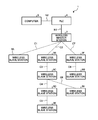
- FIG. 1 is a diagram illustrating a configuration of a communication system according to a first embodiment.
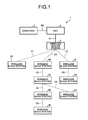
- FIG. 2 is a diagram illustrating a configuration of a wireless master station of the system according to the first embodiment.
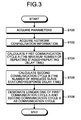
- FIG. 3 is a flowchart illustrating a process of the wireless master station of the communication system according to the first embodiment.
- FIG. 4 is a diagram explaining calculation of a first communication cycle in the communication system according to the first embodiment.
- FIG. 5 is a diagram explaining calculation of a second communication cycle in the communication system according to the first embodiment.
- FIG. 6 is a diagram illustrating a configuration of a wireless master station of a communication system according to a second embodiment.
- FIG. 7 is a flowchart illustrating a process of the wireless master station of the communication system according to the second embodiment.
- FIG. 8 is a diagram illustrating a configuration of a wireless master station of a communication system according to a third embodiment.
- FIG. 9 is a flowchart illustrating a process of the wireless master station of the communication system according to the third embodiment.
- FIG. 10 is a diagram illustrating a configuration of a wireless master station of a communication system according to a fourth embodiment.
- FIG. 11 is a flowchart illustrating a process of the wireless master station of the communication system according to the fourth embodiment.
- FIG. 12 is a flowchart illustrating a process of a wireless master station of a communication system according to a fifth embodiment.
- FIG. 1 is a diagram illustrating a configuration of a communication system according to a first embodiment of the present invention.
- the communication system 1 includes a wireless master station 2 and wireless slave stations 3 A, 3 B, 3 C, 3 D, 3 E, 3 F, 3 G, and 3 H.
- the wireless master station 2 and the wireless slave stations 3 A, 3 B, 3 C, 3 D, 3 E, 3 F, 3 G, and 3 H perform wireless multi-hop communication.
- the communication system 1 is a wireless multi-hop network.
- the communication system 1 is not limited to the wireless multi-hop network.
- the communication system 1 only needs to be a wireless network in which a communication cycle cannot be uniquely determined only by the number of wireless slave stations 3 A, 3 B, 3 C, 3 D, 3 E, 3 F, 3 G, and 3 H.
- the wireless master station 2 corresponds to the communication device of the present invention.
- Each of the wireless slave stations 3 A, 3 B, 3 C, 3 D, 3 E, 3 F, 3 G, and 3 H sends and receives data to and from the wireless master station 2 .
- the data are exemplified by sensor information.
- the wireless slave station 3 A directly communicates with the wireless master station 2 via a transmission route C 1 .
- the wireless slave station 3 B directly communicates with the wireless master station 2 via a transmission route C 2 .
- the wireless slave station 3 C communicates with the wireless master station 2 via the transmission route C 2 , the wireless slave station 3 B, and a transmission route C 3 .
- the wireless slave station 3 D communicates with the wireless master station 2 via the transmission route C 2 , the wireless slave station 3 B, the transmission route C 3 , the wireless slave station 3 C, and a transmission route C 4 .
- the wireless slave station 3 E communicates with the wireless master station 2 via the transmission route C 2 , the wireless slave station 3 B, the transmission route C 3 , the wireless slave station 3 C, the transmission route C 4 , the wireless slave station 3 D, and a transmission route C 5 .
- the wireless slave station 3 F directly communicates with the wireless master station 2 via a transmission route C 7 .
- the wireless slave station 3 G communicates with the wireless master station 2 via the transmission route C 7 , the wireless slave station 3 F, and a transmission route C 8 .
- the wireless slave station 3 H communicates with the wireless master station 2 via the transmission route C 2 , the wireless slave station 3 B, the transmission route C 3 , the wireless slave station 3 C, and a transmission route C 6 .
- the communication system 1 also includes a programmable controller (PLC, JIS B 3502: 2011) 4 and a computer 5 .
- PLC programmable controller
- the PLC 4 communicates with the wireless master station 2 via a wired network N 1 .
- the wired network N 1 is exemplified by Ethernet (registered trademark).
- the PLC 4 periodically receives data received by the wireless master station 2 .
- the computer 5 communicates with the PLC 4 via a wired network N 2 .
- the wired network N 2 is exemplified by Ethernet (registered trademark).
- An application program for monitoring and controlling data is installed on the computer 5 .
- An engineering tool program is also installed on the computer 5 .
- the engineering tool program configures parameter settings for the PLC 4, the wireless master station 2 , and the wireless slave stations 3 A, 3 B, 3 C, 3 D, 3 E, 3 F, 3 G, and 3 H.
- the engineering tool program also displays error information of the PLC 4, the wireless master station 2 , and the wireless slave stations 3 A, 3 B, 3 C, 3 D, 3 E, 3 F, 3 G, and 3 H.
- the engineering tool program also creates a control program, and sends the control program to the PLC 4.
- the control program is executed by the PLC 4 for controlling an industrial machine.
- the wireless master station 2 and the wireless slave stations 3 A, 3 B, 3 C, 3 D, 3 E, 3 F, 3 G, and 3 H autonomously construct the transmission routes based on a transmission environment.
- the transmission environment is exemplified by the quality of transmission or the number of repeater stations between the wireless master station 2 and the wireless slave stations 3 A, 3 B, 3 C, 3 D, 3 E, 3 F, 3 G, and 3 H.
- the communication system 1 has a function of a mesh network.
- the wireless master station 2 and the wireless slave stations 3 A, 3 B, 3 C, 3 D, 3 E, 3 F, 3 G, and 3 H search for alternative transmission routes before or after these stations become incommunicable, and construct transmission routes that bypass the place where the transmission environment has been deteriorated.
- the transmission routes through which the wireless master station 2 and the wireless slave stations 3 A, 3 B, 3 C, 3 D, 3 E, 3 F, 3 G, and 3 H communicate with one another are not fixed at the transmission routes C 1 , C 2 , C 3 , C 4 , C 5 , C 6 , C 7 , and C 8 illustrated in FIG. 1 .
- the transmission routes through which the wireless master station 2 and the wireless slave stations 3 A, 3 B, 3 C, 3 D, 3 E, 3 F, 3 G, and 3 H communicate with one another vary from moment to moment in accordance with the transmission environment.
- the number of repeater stations between the wireless master station 2 and the wireless slave stations 3 A, 3 B, 3 C, 3 D, 3 E, 3 F, 3 G, and 3 H also varies, and a response time between the wireless master station 2 and the wireless slave stations 3 A, 3 B, 3 C, 3 D, 3 E, 3 F, 3 G, and 3 H also varies.
- FIG. 2 is a diagram illustrating a configuration of the wireless master station of the system according to the first embodiment of the present invention.
- the wireless master station 2 includes a wireless communication unit 10 that performs wireless communication and a wired communication unit 20 that performs wired communication.
- the wireless communication unit 10 includes a wireless sending unit 101 , a wireless receiving unit 102 , and a wireless access control unit 103 .
- the wireless sending unit 101 modulates a wireless transmission frame into a radio frequency (RF) signal.
- the wireless receiving unit 102 demodulates a received RF signal into a wireless reception frame.
- the wireless access control unit 103 generates the wireless transmission frame, analyzes the wireless reception frame, and performs timing control for transmission and reception.
- the wireless communication unit 10 also has a wireless network control unit 104 and an antenna 105 .
- the wireless network control unit 104 acquires network configuration information including the maximum number of repeating stages and the number of wireless slave stations.
- the maximum number of repeating stages is the maximum value of the number of repeating stages between the wireless master station 2 and the wireless slave stations 3 A, 3 B, 3 C, 3 D, 3 E, 3 F, 3 G, and 3 H.
- the number of wireless slave stations is the total number of wireless slave stations 3 A, 3 B, 3 C, 3 D, 3 E, 3 F, 3 G, and 3 H.
- the antenna 105 sends and receives radio waves.
- the network configuration information further includes information indicating partners connected to the wireless slave stations 3 A, 3 B, 3 C, 3 D, 3 E, 3 F, 3 G, and 3 H and information on the quality of transmission between the wireless slave stations 3 A, 3 B, 3 C, 3 D, 3 E, 3 F, 3 G, and 3 H and the partners connected thereto.
- the information on the quality of transmission is exemplified by reception electric field intensity.
- the wireless sending unit 101 modulates the wireless transmission frame input from the wireless access control unit 103 into the RF signal, and sends the RF signal to the wireless slave stations 3 A, 3 B, 3 C, 3 D, 3 E, 3 F, 3 G, and 3 H via the antenna 105 .
- the wireless receiving unit 102 demodulates the RF signal received from the wireless slave stations 3 A, 3 B, 3 C, 3 D, 3 E, 3 F, 3 G, and 3 H via the antenna 105 into the wireless reception frame, and outputs the demodulated wireless reception frame to the wireless access control unit 103 .
- the wireless access control unit 103 generates the wireless transmission frame, analyzes the wireless reception frame, and performs the timing control for transmission and reception.
- the wireless network control unit 104 monitors the transmission routes to the wireless slave stations 3 A, 3 B, 3 C, 3 D, 3 E, 3 F, 3 G, and 3 H in order to maintain and construct the transmission routes. For this purpose, the wireless network control unit 104 generates a wireless network frame for monitoring the transmission routes and analyzes a response to the wireless network frame.
- the wired communication unit 20 includes a data sending unit 201 and a data receiving unit 202 .
- the data sending unit 201 sends application transmission data to the wireless communication unit 10 .
- the data receiving unit 202 receives application reception data from the wireless communication unit 10 .
- the wired communication unit 20 also includes a parameter management unit 203 that stores parameters including a delay time for communication.
- the parameters include a repeating delay time that is a delay time for a case where the wireless slave stations 3 A, 3 B, 3 C, 3 D, 3 E, 3 F, 3 G, and 3 H perform repeating and a response delay time that is a delay time for a response during communication between the wireless master station 2 and the wireless slave stations 3 A, 3 B, 3 C, 3 D, 3 E, 3 F, 3 G, and 3 H.
- the wired communication unit 20 also includes a communication cycle calculation unit 204 that calculates a communication cycle based on the network configuration information and the delay time for communication.
- the wired communication unit 20 also includes an application data control unit 205 , a wired receiving unit 206 , and a wired sending unit 207 .
- the application data control unit 205 generates the application transmission data based on a wired frame, and generates a wired frame based on the application reception data.
- the wired receiving unit 206 receives the wired frame.
- the wired sending unit 207 sends the wired frame.
- the wired receiving unit 206 receives the wired frame from the PLC 4 via the wired network N 1 , and outputs the wired frame to the application data management unit 205 .
- the application data control unit 205 generates the application transmission data based on the wired frame, and outputs the application transmission data to the data sending unit 201 .
- the data sending unit 201 outputs the application transmission data input from the application data control unit 205 to the wireless network control unit 104 of the wireless communication unit 10 .
- the data receiving unit 202 outputs the application reception data input from the wireless network control unit 104 to the application data control unit 205 .
- the application data control unit 205 generates the wired frame based on the application reception data, and outputs the wired frame to the wired sending unit 207 .
- the wired sending unit 207 outputs the wired frame to the PLC 4 via the wired network N 1 .
- the application data control unit 205 generates a control message required for monitoring the quality of transmission, transmission state, or transmission fault in the wireless network, and analyzes a response to the control message.
- the application data control unit 205 then outputs a wired frame indicating the generation result and the analysis result to the wired sending unit 207 .
- the wired frame which is the analysis result of the quality of transmission, transmission state, or transmission fault in the wireless network is sent to the computer 5 via the wired network N 1 , the PLC 4, and the wired network N 2 .
- the engineering tool program executed on the computer 5 displays the analysis result of the quality of transmission, transmission state, or transmission fault in the wireless network.
- the communication cycle calculation unit 204 acquires the network configuration information from the wireless network control unit 104 via the data receiving unit 202 .
- the communication cycle calculation unit 204 acquires the network configuration information from the wireless network control unit 104 , and acquires the parameters including the repeating delay time and the response delay time from the parameter management unit 203 .
- the communication cycle calculation unit 204 calculates the communication cycle, and outputs the calculated communication cycle to the data sending unit 201 .
- the data sending unit 201 generates application transmission data based on the communication cycle input from the communication cycle calculation unit 204 , and outputs the application transmission data to the wireless network control unit 104 .
- the communication cycle calculation unit 204 also outputs the communication cycle to the application data control unit 205 .
- the communication cycle is sent to the computer 5 via the application data control unit 205 , the wired sending unit 207 , the wired network N 1 , the PLC 4, and the wired network N 2 .
- the engineering tool program executed on the computer 5 displays the communication cycle.
- FIG. 3 is a flowchart illustrating a process of the wireless master station of the communication system according to the first embodiment of the present invention.
- step S 100 the communication cycle calculation unit 204 of the wireless master station 2 acquires the parameters from the parameter management unit 203 .
- step S 102 the communication cycle calculation unit 204 acquires the network configuration information from the wireless network control unit 104 via the data receiving unit 202 .
- step S 104 based on the maximum number of repeating stages included in the network configuration information acquired in step S 102 and the repeating delay time included in the parameters acquired in step S 100 , the communication cycle calculation unit 204 calculates a first communication cycle A. More specifically, the communication cycle calculation unit 204 calculates the first communication cycle A by multiplying the maximum number of repeating stages and the repeating delay time.
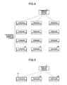
- FIG. 4 is a diagram explaining calculation of the first communication cycle in the communication system according to the first embodiment of the present invention.
- the first communication cycle A is calculated on the assumption that the number of repeating stages from the wireless master station 2 to all the wireless slave stations 3 A, 3 B, 3 C, 3 D, 3 E, 3 F, 3 G, and 3 H is the maximum number of repeating stages included in the network configuration information.
- the maximum number of repeating stages in FIG. 4 is “four”, the maximum number of repeating stages is not limited to “four”.
- the communication cycle calculation unit 204 calculates a second communication cycle B based on the number of wireless slave stations included in the network configuration information acquired in step S 102 and the response delay time included in the parameters acquired in step S 100 . More specifically, the communication cycle calculation unit 204 calculates the second communication cycle B by multiplying the number of wireless slave stations and the response delay time.
- FIG. 5 is a diagram explaining calculation of the second communication cycle in the communication system according to the first embodiment of the present invention.
- the second communication cycle B is calculated on the assumption that the number of repeater stations between the wireless master station 2 and all the wireless slave stations 3 A, 3 B, 3 C, 3 D, 3 E, 3 F, 3 G, and 3 H is 0, that is, the wireless network is a star network without a repeater.
- step S 108 the communication cycle calculation unit 204 designates longer one of the first communication cycle A and the second communication cycle B as the communication cycle.
- the communication cycle calculation unit 204 outputs the calculated communication cycle to the data sending unit 201 .
- the data sending unit 201 generates the application transmission data based on the communication cycle input from the communication cycle calculation unit 204 , and outputs the application transmission data to the wireless network control unit 104 .
- the communication cycle calculation unit 204 also outputs the communication cycle to the application data control unit 205 .
- the communication cycle is sent to the computer 5 via the application data control unit 205 , the wired sending unit 207 , the wired network N 1 , the PLC 4, and the wired network N 2 .
- the engineering tool program executed on the computer 5 displays the communication cycle.
- the wireless master station 2 uses the maximum number of repeating stages to calculate the first communication cycle A.
- the wireless master station 2 may use the average number of repeating stages.
- the wireless master station 2 uses the repeating delay time to calculate the first communication cycle A, and uses the response delay time to calculate the second communication cycle B.
- the wireless master station 2 may use one or both of the size of data sent and received between the wireless slave stations 3 A, 3 B, 3 C, 3 D, 3 E, 3 F, 3 G, and 3 H and the wireless master station 2 and the number of retransmissions in a wireless section.
- the delay time increases as the size of data increases.
- the delay time increases as the number of retransmissions increases. Therefore, the wireless master station 2 may use the size of data or the number of retransmissions instead of the repeating delay time or the response delay time.
- the wireless master station 2 may add a margin to the calculated communication cycle.
- the wireless master station 2 has the following effects.
- a short communication cycle is set, traffic in the entire wireless network is congested, and the first problem occurs: the quality of transmission is liable to be deteriorated due to occurrence of a data collision in the wireless section.
- the second problem occurs: a substantial amount of time is required for data collection.
- the wireless master station 2 can suppress a data collision in the wireless section, and determine a suitable communication cycle for suppressing a delay in data collection. Consequently, the wireless master station 2 can suppress the first and second problems mentioned above.
- the wireless master station 2 calculates the communication cycle based on the parameters stored in advance and the network configuration information acquired in advance. Therefore, the wireless master station 2 achieves an effect of eliminating the need for surveys or complicated measurement and control for the calculation of the communication cycle.
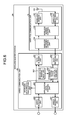
- FIG. 6 is a diagram illustrating a configuration of a wireless master station of a communication system according to a second embodiment of the present invention.
- the wireless master station 2 A according to the second embodiment further includes an aperiodic data amount calculation unit 208 in the wired communication unit 20 in addition to the configuration of the wireless master station 2 according to the first embodiment.
- the aperiodic data amount calculation unit 208 calculates the data amount of aperiodic data. In contrast to the periodic data that are sent and received periodically, the aperiodic data are sent and received aperiodically. The aperiodic data are exemplified by data of message communication.
- the aperiodic data amount calculation unit 208 acquires, from the application data control unit 205 , the number of times that the aperiodic data have actually been sent and received per unit time or the total amount of aperiodic data that has actually been sent and received per unit time. Then, based on the number of times that the aperiodic data have actually been sent and received per unit time or the total amount of aperiodic data that has actually been sent and received per unit time, the aperiodic data amount calculation unit 208 calculates an aperiodic data amount ratio which is the ratio of the aperiodic data amount to the data amount of periodic data.
- the aperiodic data amount calculation unit 208 outputs the calculated aperiodic data amount ratio to the communication cycle calculation unit 204 .
- the communication cycle calculation unit 204 corrects the communication cycle based on the communication cycle calculated on the basis of the network configuration information, the repeating delay time, and the response delay time, and on the aperiodic data amount ratio, and outputs the corrected communication cycle to the data sending unit 201 .
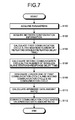
- FIG. 7 is a flowchart illustrating a process of the wireless master station of the communication system according to the second embodiment of the present invention. Since steps S 100 , S 102 , S 104 , S 106 , and S 108 in the flowchart of FIG. 7 are similar to those in the flowchart illustrated in FIG. 3 , the descriptions thereof are omitted.
- steps S 110 and S 112 are added after step S 108 .
- step S 110 based on the number of times that the aperiodic data have actually been sent and received per unit time or the total amount of aperiodic data that has actually been sent and received per unit time, the aperiodic data amount calculation unit 208 calculates the aperiodic data amount ratio which is the ratio of the aperiodic data amount to the data amount of periodic data.
- the aperiodic data amount calculation unit 208 outputs the calculated aperiodic data amount ratio to the communication cycle calculation unit 204 .
- step S 112 the communication cycle calculation unit 204 corrects the communication cycle determined in step S 108 based on the aperiodic data amount ratio calculated in step S 110 .
- the communication cycle calculation unit 204 correct and lengthen the communication cycle determined in step S 108 by an amount corresponding to the aperiodic data amount sent and received.
- the communication cycle calculation unit 204 can correct the communication cycle using the following formula:
- the communication cycle calculation unit 204 outputs the corrected communication cycle to the data sending unit 201 .
- the aperiodic data amount calculation unit 208 calculates the aperiodic data amount ratio based on the number of times that the aperiodic data have actually been sent and received per unit time or the total amount of aperiodic data that has actually been sent and received per unit time.
- the parameter management unit 203 may store, in advance as a parameter, one or both of the number of times that the aperiodic data are sent and received per unit time and the total amount of aperiodic data that is sent and received per unit time, and the aperiodic data amount calculation unit 208 may calculate the aperiodic data amount ratio based on the number of times that the aperiodic data are sent and received per unit time or the total amount of aperiodic data that is sent and received per unit time, which is stored in advance in the parameter management unit 203 as the parameter.
- the parameter management unit 203 may store the aperiodic data amount ratio in advance as a parameter.
- the wireless master station 2 A can correct the communication cycle based on the aperiodic data amount ratio. Therefore, the wireless master station 2 A can achieve an effect of suppressing traffic congestion in the wireless network due to transmission and reception of the aperiodic data, and suppressing deterioration in the quality of transmission and reception of the periodic data.
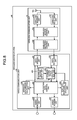
- FIG. 8 is a diagram illustrating a configuration of a wireless master station of a communication system according to a third embodiment of the present invention.
- the wireless master station 2 B according to the third embodiment further includes a test data response time calculation unit ( 209 ) 209 in the wired communication unit 20 in addition to the configuration of the wireless master station 2 A according to the second embodiment.
- the test data response time calculation unit ( 209 ) 209 sends and receives test data to and from the wireless slave stations 3 A, 3 B, 3 C, 3 D, 3 E, 3 F, 3 G, and 3 H, thereby calculating a test data response time which is a period of time from transmission of the test data to reception of the test data.
- the application data control unit 205 outputs a transmission time point for the test data and a reception time point for the test data to the test data response time calculation unit ( 209 ) 209 .
- the test data response time calculation unit ( 209 ) 209 can calculate the test data response time by calculating a difference between the transmission time point for the test data and the reception time point for the test data.
- the test data response time calculation unit ( 209 ) 209 outputs the calculated test data response time to the communication cycle calculation unit 204 .
- the communication cycle calculation unit 204 compares the test data response time with a first response time threshold value ThRT 1 stored in advance in the parameter management unit 203 as a parameter.
- the communication cycle calculation unit 204 corrects the communication cycle by multiplying the communication cycle by a correction value ⁇ 1 stored in advance in the parameter management unit 203 .
- the communication cycle calculation unit 204 outputs the corrected communication cycle to the data sending unit 201 .
- the communication cycle calculation unit 204 correct and shorten the communication cycle by multiplying the communication cycle by the correction value ⁇ 1 which is smaller than one.
- the communication cycle calculation unit 204 compares the test data response time with a second response time threshold value ThRT 2 stored in advance in the parameter management unit 203 as a parameter. Note that ThRT 2 >ThRT 1 is satisfied.
- the communication cycle calculation unit 204 corrects the communication cycle by multiplying the communication cycle by a correction value ⁇ 2 stored in advance in the parameter management unit 203 .
- the communication cycle calculation unit 204 outputs the corrected communication cycle to the data sending unit 201 .
- the communication cycle calculation unit 204 correct and lengthen the communication cycle by multiplying the communication cycle by the correction value ⁇ 2 which is larger than one.
- FIG. 9 is a flowchart illustrating a process of the wireless master station of the communication system according to the third embodiment of the present invention. Since steps S 100 , S 102 , S 104 , S 106 , S 108 , S 110 , and S 112 in the flowchart of FIG. 9 are similar to those in the flowchart illustrated in FIG. 7 , the descriptions thereof are omitted.
- steps S 114 , S 116 , S 118 , S 120 and S 122 are added after step S 112 .
- the test data response time calculation unit 209 calculates the test data response time in step S 114 .
- test data response time calculation unit 209 acquires the transmission time point for the test data and the reception time point for the test data from the application data control unit 205 , and calculates the difference between the transmission time point for the test data and the reception time point for the test data, thereby calculating the test data response time.
- the test data response time calculation unit 209 outputs the calculated test data response time to the communication cycle calculation unit 204 .
- step S 116 the communication cycle calculation unit 204 acquires the first response time threshold value ThRT 1 stored in advance in the parameter management unit 203 , and compares the test data response time with the response time threshold value ThRT 1 .
- step S 120 When the communication cycle calculation unit 204 determines that the test data response time is equal to or greater than the response time threshold value ThRT 1 (Yes), the process advances to step S 120 , and when the communication cycle calculation unit 204 determines that the test data response time is less than the response time threshold value ThRT 1 (No), the process advances to step S 118 .
- step S 118 the communication cycle calculation unit 204 corrects the communication cycle by multiplying the communication cycle by the correction value ⁇ 1 stored in advance in the parameter management unit 203 , and outputs the corrected communication cycle to the data sending unit 201 . The process is then terminated.
- the test data response time may be the average value or the maximum value of test data response times obtained through the transmission of the test data to all the wireless slave stations 3 A, 3 B, 3 C, 3 D, 3 E, 3 F, 3 G, and 3 H.
- the response time threshold value ThRT 1 may be a freely-determined value, may be determined on the basis of the maximum number of repeating stages and the repeating delay time, or may be determined on the basis of the number of wireless slave stations and the response delay time. In addition, a margin may be added to the determined response time threshold value ThRT 1 .
- the correction value al may be a freely-determined value, or may be determined on the basis of the ratio of the response time threshold value ThRT 1 to the test data response time.
- a margin may be added to the determined correction value ⁇ 1 .
- step S 120 the communication cycle calculation unit 204 acquires the second response time threshold value ThRT 2 stored in advance in the parameter management unit 203 , and compares the test data response time with the response time threshold value ThRT 2 .
- the process advances to step S 122 , and when the communication cycle calculation unit 204 determines that the test data response time is less than the response time threshold value ThRT 2 (No), the process is terminated.
- step S 122 the communication cycle calculation unit 204 corrects the communication cycle by multiplying the communication cycle by the correction value ⁇ 2 stored in advance in the parameter management unit 203 , and outputs the corrected communication cycle to the data sending unit 201 . The process is then terminated.
- the response time threshold value ThRT 2 may be a freely-determined value, may be determined on the basis of the maximum number of repeating stages and the repeating delay time, or may be determined on the basis of the number of wireless slave stations and the response delay time. In addition, a margin may be added to the determined response time threshold value ThRT 2 .
- the correction value ⁇ 2 may be a freely-determined value, or may be determined on the basis of the ratio of the response time threshold value ThRT 2 to the test data response time.
- a margin may be added to the determined correction value ⁇ 2 .
- steps S 114 , S 116 , S 118 , S 120 , and S 122 are added after step S 112 of the second embodiment illustrated in FIG. 7 .
- steps S 114 , S 116 , S 118 , S 120 , and S 122 may be added after step S 108 of the first embodiment illustrated in FIG. 3 .
- the wireless master station 2 B can correct the communication cycle based on the test data response time and the response time threshold values ThRT 1 and ThRT 2 . Consequently, the wireless master station 2 B can achieve an effect of taking account of the test data response time to determine a more suitable communication cycle.
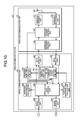
- FIG. 10 is a diagram illustrating a configuration of a wireless master station of a communication system according to a fourth embodiment of the present invention.
- the wireless master station 2 C according to the fourth embodiment further includes a transmission time calculation unit 210 in the wired communication unit 20 in addition to the configuration of the wireless master station 2 B according to the third embodiment.
- the transmission time calculation unit 210 calculates a transmission time for each wireless frame based on the number of transmission bytes of each wireless frame output from the wireless access control unit 103 and a transmission rate for wireless communication stored in advance in the parameter management unit 203 .
- the transmission time calculation unit 210 can calculate the transmission time for each wireless frame by dividing the number of transmission bytes of each wireless frame by the transmission rate for wireless communication.
- the transmission time calculation unit 210 accumulates transmission times for respective wireless frames to calculate a total transmission time per unit time.
- the transmission time calculation unit 210 compares the total transmission time with a total transmission time threshold value ThTT stored in advance in the parameter management unit 203 as a parameter.
- the total transmission time threshold value ThTT a total transmission time per unit time defined by a wireless communication standard can be adopted.
- a time shorter than the total transmission time per unit time defined by the wireless communication standard can be adopted as the total transmission time threshold value ThTT.
- the transmission time calculation unit 210 does not correct the communication cycle in a case where the total transmission time is equal to or less than the total transmission time threshold value ThTT.
- the transmission time calculation unit 210 notifies the computer 5 via the application data control unit 205 and the wired sending unit 207 that the total transmission time has exceeded the total transmission time threshold value ThTT, and also notifies the communication cycle calculation unit 204 of the same.
- the engineering tool program executed on the computer 5 displays the fact that the total transmission time has exceeded the total transmission time threshold value ThTT.
- the communication cycle calculation unit 204 corrects the communication cycle by multiplying the communication cycle by a correction value ⁇ stored in advance in the parameter management unit 203 .
- the communication cycle calculation unit 204 outputs the corrected communication cycle to the data sending unit 201 .
- the communication cycle calculation unit 204 correct and lengthen the communication cycle by multiplying the communication cycle by the correction value ⁇ which is larger than one.
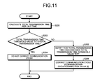
- FIG. 11 is a flowchart illustrating a process of the wireless master station of the communication system according to the fourth embodiment of the present invention.
- the wireless master station 2 C executes the process illustrated in FIG. 11 after the process illustrated in FIG. 3, 7 , or 9 .
- step S 200 the transmission time calculation unit 210 calculates the total transmission time per unit time.
- the transmission time calculation unit 210 acquires the number of transmission bytes of each wireless frame output from the wireless access control unit 103 . Then, the transmission time calculation unit 210 calculates the transmission time for each wireless frame based on the number of transmission bytes of each wireless frame and the transmission rate for wireless communication stored in advance in the parameter management unit 203 . Furthermore, the transmission time calculation unit 210 accumulates the transmission times for the respective wireless frames to calculate the total transmission time per unit time.
- the transmission time calculation unit 210 sequentially executes the process of step S 200 . Each time the transmission time calculation unit 210 calculates the total transmission time per unit time in step S 200 , the transmission time calculation unit 210 executes the process in step S 202 and subsequent steps.
- step S 202 the transmission time calculation unit 210 acquires the total transmission time threshold value ThTT stored in advance in the parameter management unit 203 , and compares the total transmission time with the total transmission time threshold value ThTT.
- step S 204 When the transmission time calculation unit 210 determines that the total transmission time is equal to or less than the total transmission time threshold value ThTT (Yes), the process advances to step S 204 , and when the transmission time calculation unit 210 determines that the total transmission time exceeds the total transmission time threshold value ThTT (No), the process advances to step S 206 .
- step S 204 the transmission time calculation unit 210 does not correct the communication cycle, and terminates the process.
- step S 206 the transmission time calculation unit 210 notifies the application data control unit 205 and the communication cycle calculation unit 204 that the total transmission time has exceeded the total transmission time threshold value ThTT.
- step S 208 the communication cycle calculation unit 204 corrects the communication cycle by multiplying the communication cycle by the correction value ⁇ stored in advance in the parameter management unit 203 , and outputs the corrected communication cycle to the data sending unit 201 .
- the correction value ⁇ may be a freely-determined value, or may be determined on the basis of the ratio of the total transmission time threshold value ThTT to the total transmission time. In addition, a margin may be added to the determined correction value ⁇ .
- the wireless master station 2 C can correct the communication cycle based on the total transmission time per unit time and the total transmission time threshold value ThTT. Consequently, the wireless master station 2 C can achieve an effect of suppressing termination of radio waves due to the total transmission time exceeding the total transmission time threshold value ThTT.
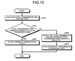
- the configuration of the wireless master station 2 C according to the fifth embodiment of the present invention is similar to the configuration of the wireless master station 2 C according to the fourth embodiment illustrated in FIG. 10 .
- FIG. 12 is a flowchart illustrating a process of the wireless master station of the communication system according to the fifth embodiment of the present invention.
- the flowchart illustrated in FIG. 12 includes step S 210 in place of step S 208 in the flowchart according to the fourth embodiment illustrated in FIG. 11 .
- the wireless master station 2 C executes the process illustrated in FIG. 12 after the process illustrated in FIG. 3, 7 , or 9 .
- the transmission time calculation unit 210 notifies the computer 5 via the application data control unit 205 and the wired sending unit 207 that the total transmission time has exceeded the total transmission time threshold value ThTT.
- the engineering tool program executed on the computer 5 displays the fact that the total transmission time has exceeded the total transmission time threshold value ThTT.
- the application data control unit 205 stops or restricts the transmission of the aperiodic data.
- step S 206 the transmission time calculation unit 210 notifies the application data control unit 205 that the total transmission time has exceeded the total transmission time threshold value ThTT.
- the application data control unit 205 stops or restricts the transmission of the aperiodic data.
- the application data control unit 205 may restrict the transmission of the aperiodic data so that the ratio between the periodic data and the aperiodic data becomes a freely-determined ratio. Alternatively, the application data control unit 205 may restrict the transmission of the aperiodic data so that the ratio between the periodic data and the aperiodic data becomes equal to the ratio of the total transmission time threshold value ThTT to the total transmission time.
- the wireless master station 2 C can stop or restrict the transmission of the aperiodic data based on the total transmission time per unit time and the total transmission time threshold value ThTT. Consequently, the wireless master station 2 C can achieve an effect of suppressing termination of radio waves due to the total transmission time exceeding the total transmission time threshold value ThTT. In addition, the wireless master station 2 C can achieve an effect of suppressing deterioration in the quality of transmission of the periodic data due to the total transmission time exceeding the total transmission time threshold value ThTT.
- the configuration described in the above-mentioned embodiments indicates an example of the contents of the present invention.
- the configuration can be combined with another well-known technique, and a part of the configuration can be omitted or changed in a range not departing from the gist of the present invention.
- 1 communication system 2 wireless master station, 3 A, 3 B, 3 C, 3 D, 3 E, 3 F, 3 G, 3 H wireless slave station, 4 PLC, 5 computer, 10 wireless communication unit, 101 wireless sending unit, 102 wireless receiving unit, 103 wireless access control unit, 104 wireless network control unit, 20 wired communication unit, 201 data sending unit, 202 data receiving unit, 203 parameter management unit, 204 communication cycle calculation unit, 205 application data control unit, 206 wired receiving unit, 207 wired sending unit, 208 aperiodic data amount calculation unit, 209 test data response time calculation unit ( 209 ), 210 transmission time calculation unit.
- 10 wireless communication unit 101 wireless sending unit, 102 wireless receiving unit, 103 wireless access control unit, 104 wireless network control unit, 20 wired communication unit, 201 data sending unit, 202 data receiving unit, 203 parameter management unit, 204 communication cycle calculation unit, 205 application data control unit, 206 wired receiving unit, 207 wired sending unit, 208 aperiodic data amount calculation unit, 209 test
Landscapes
- Engineering & Computer Science (AREA)
- Computer Networks & Wireless Communication (AREA)
- Signal Processing (AREA)
- Power Engineering (AREA)
- Mobile Radio Communication Systems (AREA)
Abstract
Description
- The present invention relates to a communication device that performs wireless communication, a communication method, and a communication system.
- Data collection in a large-scale network with specified low-power radio stations (Article 6(4) (ii) of the Enforcement Regulations for the Radio Act) has been studied. The data collection in a large-scale network is exemplified by telemetering, in which the amount measured in a remote place is transmitted to be displayed or recorded in another place, or monitoring in a large-scale factory.
- The physical layer (PHY) and the medium access control (MAC) layer specified in IEEE 802.15.4 are used for the above network. The network is configured as a wireless multi-hop network, and can collect pieces of data from a large number of terminals that exist over a wide area.
- An ad hoc network or a mesh network is included in the wireless multi-hop network.
- In the communication between a wireless master station and a wireless slave station, the wireless multi-hop network can autonomously select and use, in accordance with a transmission environment, a transmission route through which the wireless master station and the wireless slave station directly communicate with each other or a transmission route through which the wireless master station and the wireless slave station communicate with each other via another wireless slave station.
- In a star network in which the wireless master station and the wireless slave station communicate on a one-to-one basis, the transmission route between the wireless master station and the wireless slave station is fixed. Therefore, the quality of communication is degraded or communication is disabled as soon as the transmission environment is deteriorated.
- In contrast, the wireless multi-hop network enables communication through a bypass transmission route, that is, communication via another wireless slave station. Therefore, communication can be continued even when the transmission environment is deteriorated.
- In addition, in a case where the wireless multi-hop network has a large number of wireless slave stations, a plurality of options for transmission routes can be obtained. Therefore, redundancy of transmission routes is achieved, and the quality of communication can be stabilized.
- Due to the above characteristics, the actual transmission routes in the wireless multi-hop network depend on the number of wireless slave stations, an installation environment, and the transmission environment. Therefore, it is difficult to determine the communication cycle.
- As a related technique, following
Patent Literature 1 describes a transmission environment evaluation device including an operation terminal, a wireless master station, and a plurality of wireless terminals. Specifically, configurations of communication routes are concurrently switched to the set configurations at the timing designated by the operation terminal. After that, parameters such as a route for measuring a transmission path environment and a repetitive measuring execution cycle are set, and the measurement is performed (paragraphs 0039 to 0052). - In addition, following
Patent Literature 2 describes a multi-hop wireless network in which an information distribution server controls the size of data and data transmission intervals in accordance with an effective transmission rate and the total number of connected terminals (paragraphs 0056 to 0058). - Patent Literature 1: Japanese Patent Application Laid-Open No. 2008-228186
- Patent Literature 2: Japanese Patent Application Laid-Open No. 2006-174263
- In the technique described in
Patent Literature 2, however, it is not taken into consideration that the communication routes vary in accordance with the number of terminals, the installation environment, and the transmission environment. This causes the following problems. - In a case where a short communication cycle is set, traffic in the entire wireless network is congested, and the following problem occurs: the quality of transmission is liable to be deteriorated due to occurrence of a data collision in a wireless section.
- In contrast, in a case where a long communication cycle is set despite light traffic in the entire wireless network, the following problem occurs: a substantial amount of time is required for data collection.
- The present invention has been made in consideration of the above problems, and an object thereof is to obtain a communication device capable of suppressing a data collision in a wireless section and suppressing a delay in data collection.
- In order to solve the problems and achieve the object, the present invention provides a communication device to wirelessly communicate with a plurality of wireless slave stations. The communication device includes a wireless network control unit to acquire network configuration information including the number of repeating stages between the communication device and the plurality of wireless slave stations and the number of wireless slave stations that is the total number of the plurality of wireless slave stations, a parameter management unit to store a delay time for communication, and a communication cycle calculation unit to calculate a communication cycle based on the network configuration information and the delay time.
- A communication device according to the present invention can achieve an effect of suppressing a data collision in a wireless section and suppressing a delay in data collection.
-
FIG. 1 is a diagram illustrating a configuration of a communication system according to a first embodiment. -
FIG. 2 is a diagram illustrating a configuration of a wireless master station of the system according to the first embodiment. -
FIG. 3 is a flowchart illustrating a process of the wireless master station of the communication system according to the first embodiment. -
FIG. 4 is a diagram explaining calculation of a first communication cycle in the communication system according to the first embodiment. -
FIG. 5 is a diagram explaining calculation of a second communication cycle in the communication system according to the first embodiment. -
FIG. 6 is a diagram illustrating a configuration of a wireless master station of a communication system according to a second embodiment. -
FIG. 7 is a flowchart illustrating a process of the wireless master station of the communication system according to the second embodiment. -
FIG. 8 is a diagram illustrating a configuration of a wireless master station of a communication system according to a third embodiment. -
FIG. 9 is a flowchart illustrating a process of the wireless master station of the communication system according to the third embodiment. -
FIG. 10 is a diagram illustrating a configuration of a wireless master station of a communication system according to a fourth embodiment. -
FIG. 11 is a flowchart illustrating a process of the wireless master station of the communication system according to the fourth embodiment. -
FIG. 12 is a flowchart illustrating a process of a wireless master station of a communication system according to a fifth embodiment. - Hereinafter, a communication device, a communication method, and a communication system according to embodiments of the present invention will be described in detail based on the drawings. The present invention is not limited to the embodiments.
-
FIG. 1 is a diagram illustrating a configuration of a communication system according to a first embodiment of the present invention. Thecommunication system 1 includes awireless master station 2 andwireless slave stations wireless master station 2 and thewireless slave stations communication system 1 is a wireless multi-hop network. - It should be noted that the
communication system 1 is not limited to the wireless multi-hop network. Thecommunication system 1 only needs to be a wireless network in which a communication cycle cannot be uniquely determined only by the number ofwireless slave stations - The
wireless master station 2 corresponds to the communication device of the present invention. - Each of the
wireless slave stations wireless master station 2. The data are exemplified by sensor information. - The
wireless slave station 3A directly communicates with thewireless master station 2 via a transmission route C1. Thewireless slave station 3B directly communicates with thewireless master station 2 via a transmission route C2. - The
wireless slave station 3C communicates with thewireless master station 2 via the transmission route C2, thewireless slave station 3B, and a transmission route C3. Thewireless slave station 3D communicates with thewireless master station 2 via the transmission route C2, thewireless slave station 3B, the transmission route C3, thewireless slave station 3C, and a transmission route C4. - The
wireless slave station 3E communicates with thewireless master station 2 via the transmission route C2, thewireless slave station 3B, the transmission route C3, thewireless slave station 3C, the transmission route C4, thewireless slave station 3D, and a transmission route C5. - The
wireless slave station 3F directly communicates with thewireless master station 2 via a transmission route C7. Thewireless slave station 3G communicates with thewireless master station 2 via the transmission route C7, thewireless slave station 3F, and a transmission route C8. - The
wireless slave station 3H communicates with thewireless master station 2 via the transmission route C2, thewireless slave station 3B, the transmission route C3, thewireless slave station 3C, and a transmission route C6. - The
communication system 1 also includes a programmable controller (PLC, JIS B 3502: 2011) 4 and acomputer 5. - The
PLC 4 communicates with thewireless master station 2 via a wired network N1. The wired network N1 is exemplified by Ethernet (registered trademark). ThePLC 4 periodically receives data received by thewireless master station 2. - The
computer 5 communicates with thePLC 4 via a wired network N2. The wired network N2 is exemplified by Ethernet (registered trademark). An application program for monitoring and controlling data is installed on thecomputer 5. - An engineering tool program is also installed on the
computer 5. The engineering tool program configures parameter settings for thePLC 4, thewireless master station 2, and thewireless slave stations PLC 4, thewireless master station 2, and thewireless slave stations PLC 4. The control program is executed by thePLC 4 for controlling an industrial machine. - In the
communication system 1, thewireless master station 2 and thewireless slave stations wireless master station 2 and thewireless slave stations - The
communication system 1 has a function of a mesh network. In a case where the transmission environment is deteriorated, thewireless master station 2 and thewireless slave stations - Therefore, the transmission routes through which the
wireless master station 2 and thewireless slave stations FIG. 1 . In other words, the transmission routes through which thewireless master station 2 and thewireless slave stations - Due to the variations in the transmission routes between the
wireless master station 2 and thewireless slave stations wireless master station 2 and thewireless slave stations wireless master station 2 and thewireless slave stations -
FIG. 2 is a diagram illustrating a configuration of the wireless master station of the system according to the first embodiment of the present invention. Thewireless master station 2 includes awireless communication unit 10 that performs wireless communication and awired communication unit 20 that performs wired communication. - The
wireless communication unit 10 includes awireless sending unit 101, awireless receiving unit 102, and a wirelessaccess control unit 103. Thewireless sending unit 101 modulates a wireless transmission frame into a radio frequency (RF) signal. Thewireless receiving unit 102 demodulates a received RF signal into a wireless reception frame. The wirelessaccess control unit 103 generates the wireless transmission frame, analyzes the wireless reception frame, and performs timing control for transmission and reception. - The
wireless communication unit 10 also has a wirelessnetwork control unit 104 and anantenna 105. The wirelessnetwork control unit 104 acquires network configuration information including the maximum number of repeating stages and the number of wireless slave stations. The maximum number of repeating stages is the maximum value of the number of repeating stages between thewireless master station 2 and thewireless slave stations wireless slave stations antenna 105 sends and receives radio waves. - The network configuration information further includes information indicating partners connected to the
wireless slave stations wireless slave stations - The
wireless sending unit 101 modulates the wireless transmission frame input from the wirelessaccess control unit 103 into the RF signal, and sends the RF signal to thewireless slave stations antenna 105. - The
wireless receiving unit 102 demodulates the RF signal received from thewireless slave stations antenna 105 into the wireless reception frame, and outputs the demodulated wireless reception frame to the wirelessaccess control unit 103. - The wireless
access control unit 103 generates the wireless transmission frame, analyzes the wireless reception frame, and performs the timing control for transmission and reception. - The wireless
network control unit 104 monitors the transmission routes to thewireless slave stations network control unit 104 generates a wireless network frame for monitoring the transmission routes and analyzes a response to the wireless network frame. - The
wired communication unit 20 includes adata sending unit 201 and adata receiving unit 202. Thedata sending unit 201 sends application transmission data to thewireless communication unit 10. Thedata receiving unit 202 receives application reception data from thewireless communication unit 10. - The
wired communication unit 20 also includes aparameter management unit 203 that stores parameters including a delay time for communication. - The parameters include a repeating delay time that is a delay time for a case where the
wireless slave stations wireless master station 2 and thewireless slave stations - The
wired communication unit 20 also includes a communicationcycle calculation unit 204 that calculates a communication cycle based on the network configuration information and the delay time for communication. - The
wired communication unit 20 also includes an applicationdata control unit 205, awired receiving unit 206, and awired sending unit 207. The applicationdata control unit 205 generates the application transmission data based on a wired frame, and generates a wired frame based on the application reception data. Thewired receiving unit 206 receives the wired frame. Thewired sending unit 207 sends the wired frame. - The
wired receiving unit 206 receives the wired frame from thePLC 4 via the wired network N1, and outputs the wired frame to the applicationdata management unit 205. - The application
data control unit 205 generates the application transmission data based on the wired frame, and outputs the application transmission data to thedata sending unit 201. - The
data sending unit 201 outputs the application transmission data input from the applicationdata control unit 205 to the wirelessnetwork control unit 104 of thewireless communication unit 10. - The
data receiving unit 202 outputs the application reception data input from the wirelessnetwork control unit 104 to the applicationdata control unit 205. - The application
data control unit 205 generates the wired frame based on the application reception data, and outputs the wired frame to the wired sendingunit 207. - The
wired sending unit 207 outputs the wired frame to thePLC 4 via the wired network N1. - The application
data control unit 205 generates a control message required for monitoring the quality of transmission, transmission state, or transmission fault in the wireless network, and analyzes a response to the control message. The applicationdata control unit 205 then outputs a wired frame indicating the generation result and the analysis result to the wired sendingunit 207. - The wired frame which is the analysis result of the quality of transmission, transmission state, or transmission fault in the wireless network is sent to the
computer 5 via the wired network N1, thePLC 4, and the wired network N2. The engineering tool program executed on thecomputer 5 displays the analysis result of the quality of transmission, transmission state, or transmission fault in the wireless network. - The communication
cycle calculation unit 204 acquires the network configuration information from the wirelessnetwork control unit 104 via thedata receiving unit 202. - The communication
cycle calculation unit 204 acquires the network configuration information from the wirelessnetwork control unit 104, and acquires the parameters including the repeating delay time and the response delay time from theparameter management unit 203. - Then, the communication
cycle calculation unit 204 calculates the communication cycle, and outputs the calculated communication cycle to thedata sending unit 201. Thedata sending unit 201 generates application transmission data based on the communication cycle input from the communicationcycle calculation unit 204, and outputs the application transmission data to the wirelessnetwork control unit 104. - The communication
cycle calculation unit 204 also outputs the communication cycle to the applicationdata control unit 205. The communication cycle is sent to thecomputer 5 via the applicationdata control unit 205, the wired sendingunit 207, the wired network N1, thePLC 4, and the wired network N2. The engineering tool program executed on thecomputer 5 displays the communication cycle. -
FIG. 3 is a flowchart illustrating a process of the wireless master station of the communication system according to the first embodiment of the present invention. - In step S100, the communication
cycle calculation unit 204 of thewireless master station 2 acquires the parameters from theparameter management unit 203. - In step S102, the communication
cycle calculation unit 204 acquires the network configuration information from the wirelessnetwork control unit 104 via thedata receiving unit 202. - In step S104, based on the maximum number of repeating stages included in the network configuration information acquired in step S102 and the repeating delay time included in the parameters acquired in step S100, the communication
cycle calculation unit 204 calculates a first communication cycle A. More specifically, the communicationcycle calculation unit 204 calculates the first communication cycle A by multiplying the maximum number of repeating stages and the repeating delay time. -
FIG. 4 is a diagram explaining calculation of the first communication cycle in the communication system according to the first embodiment of the present invention. As illustrated inFIG. 4 , the first communication cycle A is calculated on the assumption that the number of repeating stages from thewireless master station 2 to all thewireless slave stations FIG. 4 is “four”, the maximum number of repeating stages is not limited to “four”. - Referring again to
FIG. 3 , in step S106, the communicationcycle calculation unit 204 calculates a second communication cycle B based on the number of wireless slave stations included in the network configuration information acquired in step S102 and the response delay time included in the parameters acquired in step S100. More specifically, the communicationcycle calculation unit 204 calculates the second communication cycle B by multiplying the number of wireless slave stations and the response delay time. -
FIG. 5 is a diagram explaining calculation of the second communication cycle in the communication system according to the first embodiment of the present invention. As illustrated inFIG. 5 , the second communication cycle B is calculated on the assumption that the number of repeater stations between thewireless master station 2 and all thewireless slave stations - Referring again to
FIG. 3 , in step S108, the communicationcycle calculation unit 204 designates longer one of the first communication cycle A and the second communication cycle B as the communication cycle. - The communication
cycle calculation unit 204 outputs the calculated communication cycle to thedata sending unit 201. Thedata sending unit 201 generates the application transmission data based on the communication cycle input from the communicationcycle calculation unit 204, and outputs the application transmission data to the wirelessnetwork control unit 104. The communicationcycle calculation unit 204 also outputs the communication cycle to the applicationdata control unit 205. - The communication cycle is sent to the
computer 5 via the applicationdata control unit 205, the wired sendingunit 207, the wired network N1, thePLC 4, and the wired network N2. The engineering tool program executed on thecomputer 5 displays the communication cycle. - In the above-described first embodiment, the
wireless master station 2 uses the maximum number of repeating stages to calculate the first communication cycle A. Alternatively, thewireless master station 2 may use the average number of repeating stages. - In the above-described first embodiment, the
wireless master station 2 uses the repeating delay time to calculate the first communication cycle A, and uses the response delay time to calculate the second communication cycle B. Alternatively, instead of the repeating delay time or the response delay time, thewireless master station 2 may use one or both of the size of data sent and received between thewireless slave stations wireless master station 2 and the number of retransmissions in a wireless section. The delay time increases as the size of data increases. The delay time increases as the number of retransmissions increases. Therefore, thewireless master station 2 may use the size of data or the number of retransmissions instead of the repeating delay time or the response delay time. - Furthermore, the
wireless master station 2 may add a margin to the calculated communication cycle. - The
wireless master station 2 according to the first embodiment described above has the following effects. In a case where a short communication cycle is set, traffic in the entire wireless network is congested, and the first problem occurs: the quality of transmission is liable to be deteriorated due to occurrence of a data collision in the wireless section. In contrast, in a case where a long communication cycle is set despite light traffic in the entire wireless network, the second problem occurs: a substantial amount of time is required for data collection. - By designating longer one of the first communication cycle A and the second communication cycle B as the communication cycle, the
wireless master station 2 can suppress a data collision in the wireless section, and determine a suitable communication cycle for suppressing a delay in data collection. Consequently, thewireless master station 2 can suppress the first and second problems mentioned above. - In addition, the
wireless master station 2 calculates the communication cycle based on the parameters stored in advance and the network configuration information acquired in advance. Therefore, thewireless master station 2 achieves an effect of eliminating the need for surveys or complicated measurement and control for the calculation of the communication cycle. -
FIG. 6 is a diagram illustrating a configuration of a wireless master station of a communication system according to a second embodiment of the present invention. Thewireless master station 2A according to the second embodiment further includes an aperiodic dataamount calculation unit 208 in the wiredcommunication unit 20 in addition to the configuration of thewireless master station 2 according to the first embodiment. - The aperiodic data amount
calculation unit 208 calculates the data amount of aperiodic data. In contrast to the periodic data that are sent and received periodically, the aperiodic data are sent and received aperiodically. The aperiodic data are exemplified by data of message communication. - The aperiodic data amount
calculation unit 208 acquires, from the applicationdata control unit 205, the number of times that the aperiodic data have actually been sent and received per unit time or the total amount of aperiodic data that has actually been sent and received per unit time. Then, based on the number of times that the aperiodic data have actually been sent and received per unit time or the total amount of aperiodic data that has actually been sent and received per unit time, the aperiodic data amountcalculation unit 208 calculates an aperiodic data amount ratio which is the ratio of the aperiodic data amount to the data amount of periodic data. - The aperiodic data amount
calculation unit 208 outputs the calculated aperiodic data amount ratio to the communicationcycle calculation unit 204. The communicationcycle calculation unit 204 corrects the communication cycle based on the communication cycle calculated on the basis of the network configuration information, the repeating delay time, and the response delay time, and on the aperiodic data amount ratio, and outputs the corrected communication cycle to thedata sending unit 201. -
FIG. 7 is a flowchart illustrating a process of the wireless master station of the communication system according to the second embodiment of the present invention. Since steps S100, S102, S104, S106, and S108 in the flowchart ofFIG. 7 are similar to those in the flowchart illustrated inFIG. 3 , the descriptions thereof are omitted. - In the flowchart of
FIG. 7 , steps S110 and S112 are added after step S108. - In step S110, based on the number of times that the aperiodic data have actually been sent and received per unit time or the total amount of aperiodic data that has actually been sent and received per unit time, the aperiodic data amount
calculation unit 208 calculates the aperiodic data amount ratio which is the ratio of the aperiodic data amount to the data amount of periodic data. The aperiodic data amountcalculation unit 208 outputs the calculated aperiodic data amount ratio to the communicationcycle calculation unit 204. - In step S112, the communication
cycle calculation unit 204 corrects the communication cycle determined in step S108 based on the aperiodic data amount ratio calculated in step S110. - It is preferable that the communication
cycle calculation unit 204 correct and lengthen the communication cycle determined in step S108 by an amount corresponding to the aperiodic data amount sent and received. - More specifically, the communication
cycle calculation unit 204 can correct the communication cycle using the following formula: -
(New communication cycle)=(Communication cycle determined in step S108)×(1+aperiodic data amount ratio) (1). - The communication
cycle calculation unit 204 outputs the corrected communication cycle to thedata sending unit 201. - In the above-described second embodiment, the aperiodic data amount
calculation unit 208 calculates the aperiodic data amount ratio based on the number of times that the aperiodic data have actually been sent and received per unit time or the total amount of aperiodic data that has actually been sent and received per unit time. Alternatively, theparameter management unit 203 may store, in advance as a parameter, one or both of the number of times that the aperiodic data are sent and received per unit time and the total amount of aperiodic data that is sent and received per unit time, and the aperiodic data amountcalculation unit 208 may calculate the aperiodic data amount ratio based on the number of times that the aperiodic data are sent and received per unit time or the total amount of aperiodic data that is sent and received per unit time, which is stored in advance in theparameter management unit 203 as the parameter. In addition, theparameter management unit 203 may store the aperiodic data amount ratio in advance as a parameter. - The
wireless master station 2A according to the second embodiment described above can correct the communication cycle based on the aperiodic data amount ratio. Therefore, thewireless master station 2A can achieve an effect of suppressing traffic congestion in the wireless network due to transmission and reception of the aperiodic data, and suppressing deterioration in the quality of transmission and reception of the periodic data. -
FIG. 8 is a diagram illustrating a configuration of a wireless master station of a communication system according to a third embodiment of the present invention. Thewireless master station 2B according to the third embodiment further includes a test data response time calculation unit (209) 209 in the wiredcommunication unit 20 in addition to the configuration of thewireless master station 2A according to the second embodiment. - The test data response time calculation unit (209) 209 sends and receives test data to and from the
wireless slave stations - The application
data control unit 205 outputs a transmission time point for the test data and a reception time point for the test data to the test data response time calculation unit (209) 209. The test data response time calculation unit (209) 209 can calculate the test data response time by calculating a difference between the transmission time point for the test data and the reception time point for the test data. - The test data response time calculation unit (209) 209 outputs the calculated test data response time to the communication
cycle calculation unit 204. The communicationcycle calculation unit 204 compares the test data response time with a first response time threshold value ThRT1 stored in advance in theparameter management unit 203 as a parameter. - In a case where the test data response time is less than the response time threshold value ThRT1, the communication
cycle calculation unit 204 corrects the communication cycle by multiplying the communication cycle by a correction value α1 stored in advance in theparameter management unit 203. The communicationcycle calculation unit 204 outputs the corrected communication cycle to thedata sending unit 201. - The fact that the test data response time is less than the response time threshold value ThRT1 suggests that the traffic in the entire wireless network is light. Therefore, it is preferable that the communication
cycle calculation unit 204 correct and shorten the communication cycle by multiplying the communication cycle by the correction value α1 which is smaller than one. - In addition, the communication
cycle calculation unit 204 compares the test data response time with a second response time threshold value ThRT2 stored in advance in theparameter management unit 203 as a parameter. Note that ThRT2>ThRT1 is satisfied. - In a case where the test data response time is equal to or greater than the response time threshold value ThRT2, the communication
cycle calculation unit 204 corrects the communication cycle by multiplying the communication cycle by a correction value α2 stored in advance in theparameter management unit 203. The communicationcycle calculation unit 204 outputs the corrected communication cycle to thedata sending unit 201. - The fact that the test data response time is equal to or greater than the response time threshold value ThRT2 suggests that the traffic in the entire wireless network is congested. Therefore, it is preferable that the communication
cycle calculation unit 204 correct and lengthen the communication cycle by multiplying the communication cycle by the correction value α2 which is larger than one. -
FIG. 9 is a flowchart illustrating a process of the wireless master station of the communication system according to the third embodiment of the present invention. Since steps S100, S102, S104, S106, S108, S110, and S112 in the flowchart ofFIG. 9 are similar to those in the flowchart illustrated inFIG. 7 , the descriptions thereof are omitted. - In the flowchart of
FIG. 9 , steps S114, S116, S118, S120 and S122 are added after step S112. - The test data response
time calculation unit 209 calculates the test data response time in step S114. - More specifically, the test data response
time calculation unit 209 acquires the transmission time point for the test data and the reception time point for the test data from the applicationdata control unit 205, and calculates the difference between the transmission time point for the test data and the reception time point for the test data, thereby calculating the test data response time. The test data responsetime calculation unit 209 outputs the calculated test data response time to the communicationcycle calculation unit 204. - In step S116, the communication
cycle calculation unit 204 acquires the first response time threshold value ThRT1 stored in advance in theparameter management unit 203, and compares the test data response time with the response time threshold value ThRT1. - When the communication
cycle calculation unit 204 determines that the test data response time is equal to or greater than the response time threshold value ThRT1 (Yes), the process advances to step S120, and when the communicationcycle calculation unit 204 determines that the test data response time is less than the response time threshold value ThRT1 (No), the process advances to step S118. - In step S118, the communication
cycle calculation unit 204 corrects the communication cycle by multiplying the communication cycle by the correction value α1 stored in advance in theparameter management unit 203, and outputs the corrected communication cycle to thedata sending unit 201. The process is then terminated. - The test data response time may be the average value or the maximum value of test data response times obtained through the transmission of the test data to all the
wireless slave stations - The response time threshold value ThRT1 may be a freely-determined value, may be determined on the basis of the maximum number of repeating stages and the repeating delay time, or may be determined on the basis of the number of wireless slave stations and the response delay time. In addition, a margin may be added to the determined response time threshold value ThRT1.
- Furthermore, the correction value al may be a freely-determined value, or may be determined on the basis of the ratio of the response time threshold value ThRT1 to the test data response time. In addition, a margin may be added to the determined correction value α1.
- In step S120, the communication
cycle calculation unit 204 acquires the second response time threshold value ThRT2 stored in advance in theparameter management unit 203, and compares the test data response time with the response time threshold value ThRT2. - When the communication
cycle calculation unit 204 determines that the test data response time is equal to or greater than the response time threshold value ThRT2 (Yes), the process advances to step S122, and when the communicationcycle calculation unit 204 determines that the test data response time is less than the response time threshold value ThRT2 (No), the process is terminated. - In step S122, the communication
cycle calculation unit 204 corrects the communication cycle by multiplying the communication cycle by the correction value α2 stored in advance in theparameter management unit 203, and outputs the corrected communication cycle to thedata sending unit 201. The process is then terminated. - The response time threshold value ThRT2 may be a freely-determined value, may be determined on the basis of the maximum number of repeating stages and the repeating delay time, or may be determined on the basis of the number of wireless slave stations and the response delay time. In addition, a margin may be added to the determined response time threshold value ThRT2.
- Furthermore, the correction value α2 may be a freely-determined value, or may be determined on the basis of the ratio of the response time threshold value ThRT2 to the test data response time. In addition, a margin may be added to the determined correction value α2.
- In the third embodiment, steps S114, S116, S118, S120, and S122 are added after step S112 of the second embodiment illustrated in
FIG. 7 . Alternatively, steps S114, S116, S118, S120, and S122 may be added after step S108 of the first embodiment illustrated inFIG. 3 . - The
wireless master station 2B according to the third embodiment described above can correct the communication cycle based on the test data response time and the response time threshold values ThRT1 and ThRT2. Consequently, thewireless master station 2B can achieve an effect of taking account of the test data response time to determine a more suitable communication cycle. -
FIG. 10 is a diagram illustrating a configuration of a wireless master station of a communication system according to a fourth embodiment of the present invention. Thewireless master station 2C according to the fourth embodiment further includes a transmissiontime calculation unit 210 in the wiredcommunication unit 20 in addition to the configuration of thewireless master station 2B according to the third embodiment. - The transmission
time calculation unit 210 calculates a transmission time for each wireless frame based on the number of transmission bytes of each wireless frame output from the wirelessaccess control unit 103 and a transmission rate for wireless communication stored in advance in theparameter management unit 203. The transmissiontime calculation unit 210 can calculate the transmission time for each wireless frame by dividing the number of transmission bytes of each wireless frame by the transmission rate for wireless communication. - The transmission
time calculation unit 210 accumulates transmission times for respective wireless frames to calculate a total transmission time per unit time. - The transmission
time calculation unit 210 compares the total transmission time with a total transmission time threshold value ThTT stored in advance in theparameter management unit 203 as a parameter. - As the total transmission time threshold value ThTT, a total transmission time per unit time defined by a wireless communication standard can be adopted. Alternatively, a time shorter than the total transmission time per unit time defined by the wireless communication standard can be adopted as the total transmission time threshold value ThTT.
- The transmission
time calculation unit 210 does not correct the communication cycle in a case where the total transmission time is equal to or less than the total transmission time threshold value ThTT. - In contrast, in a case where the total transmission time exceeds the total transmission time threshold value ThTT, the transmission
time calculation unit 210 notifies thecomputer 5 via the applicationdata control unit 205 and thewired sending unit 207 that the total transmission time has exceeded the total transmission time threshold value ThTT, and also notifies the communicationcycle calculation unit 204 of the same. The engineering tool program executed on thecomputer 5 displays the fact that the total transmission time has exceeded the total transmission time threshold value ThTT. - In response to receiving the notification indicating that the total transmission time has exceeded the total transmission time threshold value ThTT from the transmission
time calculation unit 210, the communicationcycle calculation unit 204 corrects the communication cycle by multiplying the communication cycle by a correction value β stored in advance in theparameter management unit 203. The communicationcycle calculation unit 204 outputs the corrected communication cycle to thedata sending unit 201. - The fact that the total transmission time has exceeded the total transmission time threshold value ThTT suggests that the traffic in the entire wireless network is congested. Therefore, it is preferable that the communication
cycle calculation unit 204 correct and lengthen the communication cycle by multiplying the communication cycle by the correction value β which is larger than one. -
FIG. 11 is a flowchart illustrating a process of the wireless master station of the communication system according to the fourth embodiment of the present invention. Thewireless master station 2C executes the process illustrated inFIG. 11 after the process illustrated inFIG. 3, 7 , or 9. - In step S200, the transmission
time calculation unit 210 calculates the total transmission time per unit time. - More specifically, the transmission
time calculation unit 210 acquires the number of transmission bytes of each wireless frame output from the wirelessaccess control unit 103. Then, the transmissiontime calculation unit 210 calculates the transmission time for each wireless frame based on the number of transmission bytes of each wireless frame and the transmission rate for wireless communication stored in advance in theparameter management unit 203. Furthermore, the transmissiontime calculation unit 210 accumulates the transmission times for the respective wireless frames to calculate the total transmission time per unit time. - The transmission
time calculation unit 210 sequentially executes the process of step S200. Each time the transmissiontime calculation unit 210 calculates the total transmission time per unit time in step S200, the transmissiontime calculation unit 210 executes the process in step S202 and subsequent steps. - In step S202, the transmission
time calculation unit 210 acquires the total transmission time threshold value ThTT stored in advance in theparameter management unit 203, and compares the total transmission time with the total transmission time threshold value ThTT. - When the transmission
time calculation unit 210 determines that the total transmission time is equal to or less than the total transmission time threshold value ThTT (Yes), the process advances to step S204, and when the transmissiontime calculation unit 210 determines that the total transmission time exceeds the total transmission time threshold value ThTT (No), the process advances to step S206. - In step S204, the transmission
time calculation unit 210 does not correct the communication cycle, and terminates the process. - In contrast, in step S206, the transmission
time calculation unit 210 notifies the applicationdata control unit 205 and the communicationcycle calculation unit 204 that the total transmission time has exceeded the total transmission time threshold value ThTT. - In step S208, the communication
cycle calculation unit 204 corrects the communication cycle by multiplying the communication cycle by the correction value β stored in advance in theparameter management unit 203, and outputs the corrected communication cycle to thedata sending unit 201. - The correction value β may be a freely-determined value, or may be determined on the basis of the ratio of the total transmission time threshold value ThTT to the total transmission time. In addition, a margin may be added to the determined correction value β.
- The
wireless master station 2C according to the fourth embodiment described above can correct the communication cycle based on the total transmission time per unit time and the total transmission time threshold value ThTT. Consequently, thewireless master station 2C can achieve an effect of suppressing termination of radio waves due to the total transmission time exceeding the total transmission time threshold value ThTT. - The configuration of the
wireless master station 2C according to the fifth embodiment of the present invention is similar to the configuration of thewireless master station 2C according to the fourth embodiment illustrated inFIG. 10 . -
FIG. 12 is a flowchart illustrating a process of the wireless master station of the communication system according to the fifth embodiment of the present invention. The flowchart illustrated inFIG. 12 includes step S210 in place of step S208 in the flowchart according to the fourth embodiment illustrated inFIG. 11 . Thewireless master station 2C executes the process illustrated inFIG. 12 after the process illustrated inFIG. 3, 7 , or 9. - In the fifth embodiment, in a case where the total transmission time exceeds the threshold value ThTT, the transmission
time calculation unit 210 notifies thecomputer 5 via the applicationdata control unit 205 and thewired sending unit 207 that the total transmission time has exceeded the total transmission time threshold value ThTT. The engineering tool program executed on thecomputer 5 displays the fact that the total transmission time has exceeded the total transmission time threshold value ThTT. - In response to receiving the notification indicating that the total transmission time has exceeded the total transmission time threshold value ThTT from the transmission
time calculation unit 210, the applicationdata control unit 205 stops or restricts the transmission of the aperiodic data. - Referring to
FIG. 12 , in step S206, the transmissiontime calculation unit 210 notifies the applicationdata control unit 205 that the total transmission time has exceeded the total transmission time threshold value ThTT. - In response to receiving the notification indicating that the total transmission time has exceeded the total transmission time threshold value ThTT from the transmission
time calculation unit 210 in step S210, the applicationdata control unit 205 stops or restricts the transmission of the aperiodic data. - The application
data control unit 205 may restrict the transmission of the aperiodic data so that the ratio between the periodic data and the aperiodic data becomes a freely-determined ratio. Alternatively, the applicationdata control unit 205 may restrict the transmission of the aperiodic data so that the ratio between the periodic data and the aperiodic data becomes equal to the ratio of the total transmission time threshold value ThTT to the total transmission time. - The
wireless master station 2C according to the fifth embodiment described above can stop or restrict the transmission of the aperiodic data based on the total transmission time per unit time and the total transmission time threshold value ThTT. Consequently, thewireless master station 2C can achieve an effect of suppressing termination of radio waves due to the total transmission time exceeding the total transmission time threshold value ThTT. In addition, thewireless master station 2C can achieve an effect of suppressing deterioration in the quality of transmission of the periodic data due to the total transmission time exceeding the total transmission time threshold value ThTT. - The configuration described in the above-mentioned embodiments indicates an example of the contents of the present invention. The configuration can be combined with another well-known technique, and a part of the configuration can be omitted or changed in a range not departing from the gist of the present invention.
- 1 communication system, 2 wireless master station, 3A, 3B, 3C, 3D, 3E, 3F, 3G, 3H wireless slave station, 4 PLC, 5 computer, 10 wireless communication unit, 101 wireless sending unit, 102 wireless receiving unit, 103 wireless access control unit, 104 wireless network control unit, 20 wired communication unit, 201 data sending unit, 202 data receiving unit, 203 parameter management unit, 204 communication cycle calculation unit, 205 application data control unit, 206 wired receiving unit, 207 wired sending unit, 208 aperiodic data amount calculation unit, 209 test data response time calculation unit (209), 210 transmission time calculation unit.
Claims (21)
Applications Claiming Priority (1)
| Application Number | Priority Date | Filing Date | Title |
|---|---|---|---|
| PCT/JP2015/062154 WO2016170607A1 (en) | 2015-04-21 | 2015-04-21 | Communication device, communication method and communication system |
Publications (2)
| Publication Number | Publication Date |
|---|---|
| US20180098362A1 true US20180098362A1 (en) | 2018-04-05 |
| US10314107B2 US10314107B2 (en) | 2019-06-04 |
Family
ID=57142958
Family Applications (1)
| Application Number | Title | Priority Date | Filing Date |
|---|---|---|---|
| US15/549,008 Active US10314107B2 (en) | 2015-04-21 | 2015-04-21 | Communication device, communication method, and communication system |
Country Status (7)
| Country | Link |
|---|---|
| US (1) | US10314107B2 (en) |
| JP (1) | JP6038411B1 (en) |
| KR (1) | KR101925742B1 (en) |
| CN (1) | CN107534985B (en) |
| DE (1) | DE112015006175B4 (en) |
| TW (1) | TWI599194B (en) |
| WO (1) | WO2016170607A1 (en) |
Cited By (5)
| Publication number | Priority date | Publication date | Assignee | Title |
|---|---|---|---|---|
| CN112202637A (en) * | 2020-09-30 | 2021-01-08 | 西安热工研究院有限公司 | A calculation method for the number of PROFIBUS-PA bus segment devices |
| US11240725B2 (en) * | 2018-12-06 | 2022-02-01 | Kabushiki Kaisha Toshiba | Wireless communication device, wireless communication system, wireless communication method, and computer program product |
| US11490277B2 (en) * | 2017-09-04 | 2022-11-01 | Fujitsu Limited | Communication apparatus, communication system, and communication control method |
| US20230038515A1 (en) * | 2021-08-05 | 2023-02-09 | Qualcomm Incorporated | Techniques for aperiodic discontinuous reception mode communications |
| US12041000B2 (en) | 2021-08-05 | 2024-07-16 | Qualcomm Incorporated | Techniques for communicating data channel transmissions |
Families Citing this family (6)
| Publication number | Priority date | Publication date | Assignee | Title |
|---|---|---|---|---|
| JP6967738B2 (en) * | 2017-09-01 | 2021-11-17 | パナソニックIpマネジメント株式会社 | Communication systems, lighting control systems, and communication devices |
| KR102364386B1 (en) * | 2017-11-30 | 2022-02-17 | 재단법인대구경북과학기술원 | Electronic device for cyber physical systems and control method thereof |
| JP2020096242A (en) * | 2018-12-11 | 2020-06-18 | パナソニック株式会社 | Smart meter |
| CN109768825B (en) * | 2019-02-26 | 2021-10-15 | 湖南省星岳天璇科技有限公司 | High-orbit satellite operation control user information outbound control method and device |
| CN115428405B (en) * | 2020-04-24 | 2024-07-19 | 三菱电机株式会社 | Communication device, communication system, communication method and recording medium |
| KR102374722B1 (en) * | 2020-09-29 | 2022-03-14 | 엘에스일렉트릭(주) | Communication parameter setting device |
Citations (1)
| Publication number | Priority date | Publication date | Assignee | Title |
|---|---|---|---|---|
| JP2014183470A (en) * | 2013-03-19 | 2014-09-29 | Mitsubishi Electric Corp | Radio communication device and radio communication system |
Family Cites Families (21)
| Publication number | Priority date | Publication date | Assignee | Title |
|---|---|---|---|---|
| JPH0597142U (en) | 1992-05-27 | 1993-12-27 | 日本ビクター株式会社 | Wireless communication device |
| JP3349853B2 (en) * | 1994-12-27 | 2002-11-25 | 富士通株式会社 | Wireless LAN system |
| US5872774A (en) * | 1997-09-19 | 1999-02-16 | Qualcomm Incorporated | Mobile station assisted timing synchronization in a CDMA communication system |
| JP2000267892A (en) | 1999-03-19 | 2000-09-29 | Nec Corp | Collection system for remote supervisory information |
| JP2004023564A (en) | 2002-06-18 | 2004-01-22 | Canon Inc | Wireless communication control device and method |
| JP2006174263A (en) | 2004-12-17 | 2006-06-29 | Nippon Telegr & Teleph Corp <Ntt> | Multi-hop wireless network |
| JP4591104B2 (en) | 2005-02-09 | 2010-12-01 | ソニー株式会社 | Wireless communication apparatus, wireless communication method and program |
| EP1760563B1 (en) * | 2005-08-31 | 2009-10-14 | Omron Corporation | Communication system with master, slave and repeater units |
| JP4463237B2 (en) | 2006-04-28 | 2010-05-19 | 株式会社ソニー・コンピュータエンタテインメント | COMMUNICATION DEVICE, GAME DEVICE, WIRELESS GAME CONTROLLER, AND GAME SYSTEM |
| JP2008228186A (en) | 2007-03-15 | 2008-09-25 | Ad-Sol Nissin Corp | Equipment for evaluating transmission environment in multi-hop wireless networks |
| US8867983B2 (en) * | 2007-09-19 | 2014-10-21 | Fujitsu Semiconductor Limited | Method and apparatus for controlling a relay station in a multi-hop relay network |
| EP2221209B1 (en) * | 2007-12-13 | 2016-03-16 | Mitsubishi Electric Corporation | Train communication system, communication device, and relay device |
| WO2010044210A1 (en) * | 2008-10-15 | 2010-04-22 | パナソニック株式会社 | Communication device and communication method |
| JP5241524B2 (en) * | 2009-01-09 | 2013-07-17 | 株式会社日立製作所 | Optical communication system and operation method thereof |
| EP2413646A4 (en) * | 2009-07-15 | 2012-08-01 | Panasonic Corp | RADIO COMMUNICATION DEVICE, RADIO COMMUNICATION SYSTEM, RADIO COMMUNICATION METHOD, AND RADIO COMMUNICATION METHOD EXECUTION PROGRAM |
| US9385826B2 (en) * | 2011-02-21 | 2016-07-05 | Mitsubishi Electric Corporation | Communication apparatus and communication method |
| EP2760182B1 (en) * | 2011-09-21 | 2017-03-01 | Fujitsu Limited | Data communication apparatus, data transmission method, and computer system |
| JP5814154B2 (en) | 2012-02-17 | 2015-11-17 | Kddi株式会社 | Gateway, sensor network system, sensor control method, and program |
| US11039408B2 (en) * | 2012-06-07 | 2021-06-15 | Apple Inc. | Methods and apparatus for synchronization among integrated circuits within a wireless network |
| CN105164978A (en) * | 2013-05-02 | 2015-12-16 | 三菱电机株式会社 | Master device, slave device, optical communication system, control device, and bandwidth allocation method |
| US10219237B2 (en) * | 2013-11-22 | 2019-02-26 | Telefonaktiebolaget Lm Ericsson (Publ) | User equipment and method for estimating and updating a timing of a cell in a wireless communications network |
-
2015
- 2015-04-21 KR KR1020177029884A patent/KR101925742B1/en active Active
- 2015-04-21 DE DE112015006175.4T patent/DE112015006175B4/en active Active
- 2015-04-21 CN CN201580079108.7A patent/CN107534985B/en active Active
- 2015-04-21 US US15/549,008 patent/US10314107B2/en active Active
- 2015-04-21 JP JP2016536271A patent/JP6038411B1/en active Active
- 2015-04-21 WO PCT/JP2015/062154 patent/WO2016170607A1/en not_active Ceased
-
2016
- 2016-04-19 TW TW105112111A patent/TWI599194B/en active
Patent Citations (1)
| Publication number | Priority date | Publication date | Assignee | Title |
|---|---|---|---|---|
| JP2014183470A (en) * | 2013-03-19 | 2014-09-29 | Mitsubishi Electric Corp | Radio communication device and radio communication system |
Non-Patent Citations (1)
| Title |
|---|
| RADIO COMMUNICATION DEVICE AND RADIO COMMUNICATION SYSTEM JP-2014-183470-A * |
Cited By (6)
| Publication number | Priority date | Publication date | Assignee | Title |
|---|---|---|---|---|
| US11490277B2 (en) * | 2017-09-04 | 2022-11-01 | Fujitsu Limited | Communication apparatus, communication system, and communication control method |
| US11240725B2 (en) * | 2018-12-06 | 2022-02-01 | Kabushiki Kaisha Toshiba | Wireless communication device, wireless communication system, wireless communication method, and computer program product |
| CN112202637A (en) * | 2020-09-30 | 2021-01-08 | 西安热工研究院有限公司 | A calculation method for the number of PROFIBUS-PA bus segment devices |
| US20230038515A1 (en) * | 2021-08-05 | 2023-02-09 | Qualcomm Incorporated | Techniques for aperiodic discontinuous reception mode communications |
| US11985597B2 (en) * | 2021-08-05 | 2024-05-14 | Qualcomm Incorporated | Techniques for aperiodic discontinuous reception mode communications |
| US12041000B2 (en) | 2021-08-05 | 2024-07-16 | Qualcomm Incorporated | Techniques for communicating data channel transmissions |
Also Published As
| Publication number | Publication date |
|---|---|
| JPWO2016170607A1 (en) | 2017-04-27 |
| TWI599194B (en) | 2017-09-11 |
| DE112015006175T5 (en) | 2017-10-26 |
| JP6038411B1 (en) | 2016-12-07 |
| DE112015006175B4 (en) | 2019-01-17 |
| US10314107B2 (en) | 2019-06-04 |
| WO2016170607A1 (en) | 2016-10-27 |
| CN107534985B (en) | 2019-01-25 |
| KR20170121300A (en) | 2017-11-01 |
| CN107534985A (en) | 2018-01-02 |
| KR101925742B1 (en) | 2018-12-05 |
| TW201640843A (en) | 2016-11-16 |
Similar Documents
| Publication | Publication Date | Title |
|---|---|---|
| US10314107B2 (en) | Communication device, communication method, and communication system | |
| US8953645B2 (en) | Communication system, communication apparatus and time synchronization method | |
| US8553664B2 (en) | Field optimized, configurable wireless fire system | |
| US8194636B1 (en) | Adaptive timing synchronization for mesh networks | |
| KR101343565B1 (en) | Wireless access point, method and apparatus for controling thereof | |
| EP2308186B1 (en) | Techniques for monitoring the quality of short-range wireless links | |
| US20120155301A1 (en) | Wireless Network System and Wireless Communication Device | |
| Chang et al. | Accuracy-aware interference modeling and measurement in wireless sensor networks | |
| CN105764083A (en) | RSSI compensation method, device and base station | |
| KR20220104255A (en) | Monitoring service quality and experience quality | |
| US10645726B2 (en) | Wireless communication terminal, wireless communication method, and recording medium | |
| JP5884812B2 (en) | Communication apparatus and wireless communication system | |
| US10477500B2 (en) | Time distribution scheme for wireless mesh networks | |
| JP2015088807A (en) | Wireless communication apparatus and wireless information collecting system | |
| US11223931B2 (en) | Wireless sensor system, wireless terminal device, relay device, communication control method, and communication control program | |
| US20180263007A1 (en) | Time distribution scheme for wireless mesh networks | |
| JP6620162B2 (en) | Wireless communication between the access network and the terminal within the range of the access network half-duplex base stations | |
| US9681364B2 (en) | Wireless communication system, management device, wireless device, and wireless communication method | |
| EP2730039B1 (en) | Control of transmitter configuration for base station | |
| US20170359738A1 (en) | Method and Device for Data Transmission in Wireless Communication Network | |
| JP7428253B2 (en) | Server device, monitoring method, and program | |
| JP6656128B2 (en) | Wireless communication system | |
| CN106063318A (en) | Method and wireless device for managing probe messages | |
| KR102158767B1 (en) | Methods and apparatuses for routing using heterogeneous communication method | |
| US20240049058A1 (en) | Wireless communication management apparatus, wireless communication management method, and wireless communication management program |
Legal Events
| Date | Code | Title | Description |
|---|---|---|---|
| AS | Assignment |
Owner name: MITSUBISHI ELECTRIC CORPORATION, JAPAN Free format text: ASSIGNMENT OF ASSIGNORS INTEREST;ASSIGNOR:YAMAUCHI, TAKAHISA;REEL/FRAME:043206/0871 Effective date: 20170627 |
|
| STPP | Information on status: patent application and granting procedure in general |
Free format text: NOTICE OF ALLOWANCE MAILED -- APPLICATION RECEIVED IN OFFICE OF PUBLICATIONS |
|
| STPP | Information on status: patent application and granting procedure in general |
Free format text: PUBLICATIONS -- ISSUE FEE PAYMENT RECEIVED |
|
| STPP | Information on status: patent application and granting procedure in general |
Free format text: PUBLICATIONS -- ISSUE FEE PAYMENT VERIFIED |
|
| STCF | Information on status: patent grant |
Free format text: PATENTED CASE |
|
| MAFP | Maintenance fee payment |
Free format text: PAYMENT OF MAINTENANCE FEE, 4TH YEAR, LARGE ENTITY (ORIGINAL EVENT CODE: M1551); ENTITY STATUS OF PATENT OWNER: LARGE ENTITY Year of fee payment: 4 |