US20140291663A1 - High stability spintronic memory - Google Patents
High stability spintronic memory Download PDFInfo
- Publication number
- US20140291663A1 US20140291663A1 US13/996,603 US201313996603A US2014291663A1 US 20140291663 A1 US20140291663 A1 US 20140291663A1 US 201313996603 A US201313996603 A US 201313996603A US 2014291663 A1 US2014291663 A1 US 2014291663A1
- Authority
- US
- United States
- Prior art keywords
- layer
- product
- free
- oxide
- tunnel barrier
- Prior art date
- Legal status (The legal status is an assumption and is not a legal conclusion. Google has not performed a legal analysis and makes no representation as to the accuracy of the status listed.)
- Granted
Links
Images


Classifications
-
- H01L43/10—
-
- H—ELECTRICITY
- H10—SEMICONDUCTOR DEVICES; ELECTRIC SOLID-STATE DEVICES NOT OTHERWISE PROVIDED FOR
- H10N—ELECTRIC SOLID-STATE DEVICES NOT OTHERWISE PROVIDED FOR
- H10N50/00—Galvanomagnetic devices
- H10N50/80—Constructional details
- H10N50/85—Materials of the active region
-
- G—PHYSICS
- G11—INFORMATION STORAGE
- G11C—STATIC STORES
- G11C11/00—Digital stores characterised by the use of particular electric or magnetic storage elements; Storage elements therefor
- G11C11/02—Digital stores characterised by the use of particular electric or magnetic storage elements; Storage elements therefor using magnetic elements
- G11C11/14—Digital stores characterised by the use of particular electric or magnetic storage elements; Storage elements therefor using magnetic elements using thin-film elements
- G11C11/15—Digital stores characterised by the use of particular electric or magnetic storage elements; Storage elements therefor using magnetic elements using thin-film elements using multiple magnetic layers
-
- G—PHYSICS
- G11—INFORMATION STORAGE
- G11C—STATIC STORES
- G11C11/00—Digital stores characterised by the use of particular electric or magnetic storage elements; Storage elements therefor
- G11C11/02—Digital stores characterised by the use of particular electric or magnetic storage elements; Storage elements therefor using magnetic elements
- G11C11/16—Digital stores characterised by the use of particular electric or magnetic storage elements; Storage elements therefor using magnetic elements using elements in which the storage effect is based on magnetic spin effect
- G11C11/161—Digital stores characterised by the use of particular electric or magnetic storage elements; Storage elements therefor using magnetic elements using elements in which the storage effect is based on magnetic spin effect details concerning the memory cell structure, e.g. the layers of the ferromagnetic memory cell
-
- H—ELECTRICITY
- H01—ELECTRIC ELEMENTS
- H01F—MAGNETS; INDUCTANCES; TRANSFORMERS; SELECTION OF MATERIALS FOR THEIR MAGNETIC PROPERTIES
- H01F10/00—Thin magnetic films, e.g. of one-domain structure
- H01F10/32—Spin-exchange-coupled multilayers, e.g. nanostructured superlattices
- H01F10/324—Exchange coupling of magnetic film pairs via a very thin non-magnetic spacer, e.g. by exchange with conduction electrons of the spacer
- H01F10/3286—Spin-exchange coupled multilayers having at least one layer with perpendicular magnetic anisotropy
-
- H—ELECTRICITY
- H01—ELECTRIC ELEMENTS
- H01F—MAGNETS; INDUCTANCES; TRANSFORMERS; SELECTION OF MATERIALS FOR THEIR MAGNETIC PROPERTIES
- H01F10/00—Thin magnetic films, e.g. of one-domain structure
- H01F10/32—Spin-exchange-coupled multilayers, e.g. nanostructured superlattices
- H01F10/324—Exchange coupling of magnetic film pairs via a very thin non-magnetic spacer, e.g. by exchange with conduction electrons of the spacer
- H01F10/329—Spin-exchange coupled multilayers wherein the magnetisation of the free layer is switched by a spin-polarised current, e.g. spin torque effect
-
- H01L43/12—
-
- H—ELECTRICITY
- H10—SEMICONDUCTOR DEVICES; ELECTRIC SOLID-STATE DEVICES NOT OTHERWISE PROVIDED FOR
- H10N—ELECTRIC SOLID-STATE DEVICES NOT OTHERWISE PROVIDED FOR
- H10N50/00—Galvanomagnetic devices
- H10N50/01—Manufacture or treatment
-
- H—ELECTRICITY
- H10—SEMICONDUCTOR DEVICES; ELECTRIC SOLID-STATE DEVICES NOT OTHERWISE PROVIDED FOR
- H10N—ELECTRIC SOLID-STATE DEVICES NOT OTHERWISE PROVIDED FOR
- H10N50/00—Galvanomagnetic devices
- H10N50/10—Magnetoresistive devices
-
- H—ELECTRICITY
- H10—SEMICONDUCTOR DEVICES; ELECTRIC SOLID-STATE DEVICES NOT OTHERWISE PROVIDED FOR
- H10N—ELECTRIC SOLID-STATE DEVICES NOT OTHERWISE PROVIDED FOR
- H10N52/00—Hall-effect devices
- H10N52/01—Manufacture or treatment
-
- H—ELECTRICITY
- H10—SEMICONDUCTOR DEVICES; ELECTRIC SOLID-STATE DEVICES NOT OTHERWISE PROVIDED FOR
- H10N—ELECTRIC SOLID-STATE DEVICES NOT OTHERWISE PROVIDED FOR
- H10N52/00—Hall-effect devices
- H10N52/101—Semiconductor Hall-effect devices
Definitions
- Embodiments of the invention are in the field of semiconductor devices and, in particular, highly stable spintronic memory.
- FIG. 1 includes spin transfer torque random access memory (STTRAM), a form of STTM.
- STTRAM spin transfer torque random access memory
- FIG. 1 includes a MTJ consisting of ferromagnetic (FM) layers 125 , 127 and tunneling barrier 126 (e.g., magnesium oxide (MgO)).
- the MTJ couples bit line (BL) 105 to selection switch 120 (e.g., transistor), word line (WL) 110 , and sense line (SL) 115 .
- Memory 100 is “read” by assessing the change of resistance (e.g., tunneling magnetoresistance (TMR)) for different relative magnetizations of FM layers 125 , 127 .
- TMR tunneling magnetoresistance
- MTJ resistance is determined by the relative magnetization directions of layers 125 , 127 .
- Layer 127 is the “reference layer” or “fixed layer” because its magnetization direction is fixed.
- Layer 125 is the “free layer” because its magnetization direction is changed by passing a driving current polarized by the reference layer (e.g., a positive voltage applied to layer 127 rotates the magnetization direction of layer 125 opposite to that of layer 127 and negative voltage applied to layer 127 rotates the magnetization direction of layer 125 to the same direction of layer 127 ).
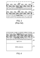
- FIG. 1 depicts a conventional magnetic memory cell.
- FIGS. 2-3 depict conventional MTJs.
- FIG. 4 includes an MTJ portion in an embodiment of the invention.
- FIG. 5 demonstrates how stability increases for an embodiment of the invention.
- FIG. 6 includes an MTJ portion in an embodiment of the invention.
- FIG. 7 includes an MTJ with a multi-layer stack in an embodiment of the invention.
- FIG. 8 includes a memory cell in an embodiment of the invention.
- FIG. 9 depicts a system for use with embodiments of the invention.
- FIG. 10 depicts a method of forming a memory in an embodiment of the invention.
- CMOS complementary metal-oxide-semiconductor
- spin polarization which concerns the degree to which the spin or intrinsic angular momentum of elementary particles is aligned with a given direction
- spintronics a branch of electronics concerning the intrinsic spin of an electron, its associated magnetic moment, and the electron's fundamental electronic charge
- TMR Spintronics devices
- STT spin polarized electrons
- CMOS devices include, for example, spintronics devices implemented in memory (e.g., 3 terminal STTRAM), spin logic devices (e.g., logic gates), tunnel field-effect transistors (TFETs), impact ionization MOS (IMOS) devices, nano-electro-mechanical switches (NEMS), negative common gate FETs, resonant tunneling diodes (RTD), single electron transistors (SET), spin FETs, nanomagnet logic (NML), domain wall logic, domain wall memory, and the like.
- spintronics devices implemented in memory (e.g., 3 terminal STTRAM), spin logic devices (e.g., logic gates), tunnel field-effect transistors (TFETs), impact ionization MOS (IMOS) devices, nano-electro-mechanical switches (NEMS), negative common gate FETs, resonant tunneling diodes (RTD), single electron transistors (SET), spin FETs, nanomagnet logic (NML), domain wall logic, domain wall memory, and the like.
- one form of STTM includes perpendicular STTM (pSTTM).
- pSTTM perpendicular STTM
- a perpendicular MTJ generates magnetization “out of plane”. This reduces the switching current needed to switch between high and low memory states. This also allows for better scaling (e.g., smaller size memory cells).
- Traditional MTJs are converted to pMTJs by, for example, thinning the free layer, thereby making the tunnel barrier/free layer interface more dominant in magnetic field influence (and the interface promotes anisotropic out of plane magnetization).
- FIG. 2 includes such a system with CoFeB free layer 225 interfacing MgO tunnel barrier 226 , which further couples to CoFeB fixed layer 227 and Tantalum (Ta) contacts 214 (which may couple to a selection switch such as transistor 120 of FIG. 1 ), 216 (which may couple, by way of one or more vias, to a bit line such as bit line 105 of FIG. 1 ).
- CoFeB free layer 225 interfacing MgO tunnel barrier 226 , which further couples to CoFeB fixed layer 227 and Tantalum (Ta) contacts 214 (which may couple to a selection switch such as transistor 120 of FIG. 1 ), 216 (which may couple, by way of one or more vias, to a bit line such as bit line 105 of FIG. 1 ).
- Ta Tantalum
- FIG. 3 depicts a MTJ, where a second oxidized MgO interface 320 contacts CoFeB free layer 325 (which further couples to a tunnel barrier MgO 326 , which is formed on CoFeB fixed layer 327 ). Doing so may increase stability for the memory, which is a problem for devices such as the device of FIG. 2 .
- FIG. 3 includes MgO at both free layer interfaces (i.e., layers 320 , 326 ).
- introducing MgO layer 320 on top of CoFeB free layer 325 increases total resistance significantly (as compared to having just one oxide layer interface the free layer as in FIG.
- MgO layer 326 is predominately responsible for resistance and voltage drop in conventional MTJs, adding yet another layer of MgO in series with layer 326 increases RA product, thereby driving up write voltage, decreasing battery life, and the like.
- a select transistor e.g., MOS transistor 120 of FIG. 1
- FIG. 4 differs from FIG. 3 , however, and includes an MTJ portion in an embodiment of the invention having an oxidized layer that includes tantalum oxide (TaO) interface 420 .
- TaO tantalum oxide
- Layer 420 contacts Co 20 Fe 60 B 20 free layer 425 , which further couples to MgO layer 426 , a substrate (layer 414 ), and other layers not necessarily shown.
- the stack in FIG. 4 was used to generate the EHE data of FIG. 5 , which is discussed below. No fixed layer is included in the stack in order to better focus on the EHE effects of adding the second oxide on the free layer. The presence of the fixed layer would not have aided in generating the data of FIG.
- “Second oxide film” 420 (i.e., a second oxide film in addition to tunnel barrier, which constitutes a “first oxide film”) enhances thermal stability (strength) of free layer 425 , thereby decreasing the odds of faulty high/low or low/high memory state conversions.
- the insertion of oxide layer 420 may be included with CoFeB free film 425 , which could have already been thinned to further promote anisotropic magnetic properties for the pSTTM.
- layer 425 is primarily located in the horizontal plane and free layer 425 has a thickness, orthogonal to the plane (vertical dimension), of less than 2 nm while oxide layer 426 has a thickness less than 3 nm (and greater than the thickness of free layer 425 ).
- layer 426 may include a thickness of about 1 nm, with an RA product of about 10 ohm-um 2 .
- Layer 426 thickness may be thicker or thinner (and consequently RA product can vary around 10 ohm-um 2 as well) in other embodiments.
- Some embodiments may include a 2-3 nm thick layer 426 .
- Free layer 425 thickness may be around 1-2 nm, but other embodiments are not so limited.
- Layer 420 may vary accordingly to gain an RA product much less than the RA product of layer 426 (e.g., so series resistance addition is negligible or low).
- an embodiment may include an RA product of 10 ohm-um 2 for layer 426 (e.g., MgO) and an RA product 10 ⁇ lower for layer 420 so the effect of layer 420 on electrical resistance is much smaller than that of layer 426 .
- FIG. 4 is an example of a more general concept for embodiments of the invention whereby a high conductivity oxide, such as layer 420 , is formed next to an interface of CoFeB free layer 425 .
- a high conductivity oxide such as layer 420
- TMR magnetic resonance
- FIG. 5 demonstrates stability increases for the embodiment of FIG. 4 .
- FIG. 5 concerns a free layer connected to tantalum (Ta) and a tunnel barrier (see circle plot points) compared to a free layer connected to tantalum oxide (TaO) and a tunnel barrier (see square plot points).
- Ta tantalum
- TaO tantalum oxide
- TaO tantalum oxide
- Ru Ruthenium
- the narrow gap for the tunnel barrier/free layer/Ta/Ru arrangement has a very narrow horizontal band that shows a quick Extraordinary Hall Effect (EHE) transition over a short magnetic field deviation (indicating low stability or coercivity).
- EHE Extraordinary Hall Effect
- the broader horizontal gap for the tunnel barrier/free layer/TaO arrangement has a broader band that shows a more tolerant EHE transition over a broader magnetic field deviation (indicating higher stability or coercivity).
- the barrier/free layer/TaO arrangement has a 4 ⁇ coercivity improvement over the tunnel barrier/free layer/Ta/Ru arrangement.
- This second oxidized interface (interface between layers 425 , 420 ) can be designed with an RA product much lower than the RA product for the tunnel barrier.
- a high-conductivity oxide i.e., lower RA product
- the conductive oxide of layer 420 may be 100-1000 ⁇ less conductive than the tunnel barrier.
- tunnel barrier MgO may have a resistivity of about 1 ohm-cm.
- the high conductivity oxide may include, for example, any one or more of the following: tungsten oxide (WO 2 ), vanadium oxide (VO and/or V 2 O 2 ), indium oxide (InOx), aluminum oxide (Al 2 O 3 ), ruthenium oxide (RuOx), and/or TaO.
- tungsten oxide WO 2
- vanadium oxide VO and/or V 2 O 2
- indium oxide InOx
- aluminum oxide Al 2 O 3
- RuOx ruthenium oxide
- TaO ruthenium oxide
- In 2 O 3 includes a tunable resistivity of 1-10 mOhm-cm
- VO 2 and V 2 O 3 include resistivity less that 1 mOhm-cm
- WO 2 includes resistivity less than 1 mOhm-cm
- tin (Sn) doped In 2 O 3 (ITO) includes resistivity less than 0.1 mOhm-cm.
- FIG. 6 shows second barrier 620 placed between CoFeB 625 and Ta contact 616 .
- Free layer 625 is on tunnel barrier 626 and fixed layer 627 .
- FIG. 7 shows second oxide barrier 720 placed between CoFeB 725 and a multi-layer arrangement 713 including alternating Cobalt (Co) and Palladium (Pd) layers that help enhance stability for the small film MTJ.
- Second oxide barrier 720 may be adjacent thinned CoFeB free layer 725 , which interfaces first oxide layer MgO spin filter 726 (which is on fixed layer 727 and below Ta contact layer 716 ).
- Thinned CoFeB free layer 725 provides a layer with strong spin-orbit coupling to render perpendicular anisotropy.
- various embodiments introduce a second oxidized layer next to the free layer, which enhances stability through dual oxidized interfaces (on top and bottom of the free layer) without adversely affecting RA product or TMR (i.e., overly increasing RA product or overly diminishing TMR). Accordingly, the second oxidized layer has a low RA product as compared to the tunnel barrier.
- Some embodiments include this second oxidized layer with a free layer and a multi-layer stack.
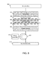
- FIG. 8 includes a memory cell in an embodiment of the invention.
- the MTJ comprises fixed/free layers 827 , 825 , tunnel barrier 826 , and oxide layer 820 .
- the MTJ couples bit line 805 to selection switch 821 (e.g., transistor), word line 810 , and sense line 815 .
- the MTJ may be located on a substrate.
- the substrate is a bulk semiconductive material as part of a wafer.
- the semiconductive substrate is a bulk semiconductive material as part of a chip that has been singulated from a wafer.
- the semiconductive substrate is a semiconductive material that is formed above an insulator such as a semiconductor on insulator (SOI) substrate.
- SOI semiconductor on insulator
- the semiconductive substrate is a prominent structure such as a fin that extends above a bulk semiconductive material. There may be one or more layers between the MTJ and the substrate. There may be one or more layers above the MTJ.
- An embodiment includes a method 1000 of forming an apparatus ( FIG. 10 ).
- a fixed layer of a MTJ is formed over a substrate.
- a tunnel barrier (first oxide layer) is formed over the fixed layer.
- a free layer is formed over the tunnel barrier.
- an oxidized layer (second oxide layer) is formed on the free layer.
- the free and fixed layers, the tunnel barrier, and the oxidized layer are all thin films (a layer less than several micrometers in thickness).
- the entire stack is deposited in-situ (without vacuum breaks) in an embodiment.
- perpendicular STTM While several embodiments herein describe perpendicular STTM, other embodiments are not so limited and may concern in plane (non-perpendicular) STTM, as well as embodiments that are neither fully in plane (non-perpendicular) or fully out of plane (perpendicular) but are instead something in between in plane and out of plane.
- a first oxide layer is said to “directly contact” the tunnel barrier layer and/or a first side of the free layer; and a second oxide layer “directly contacts” a second side of the free layer.
- the tunnel barrier may include oxide but may further include further oxidation at its surface/interface to the free layer. Such a situation would still comprise an oxide layer contacting both the free layer and the tunnel barrier. Further, for example, there can be some oxidation of the CoFeB layer during the formation of the second metal oxide.
- the metal oxide (second oxide layer) is directly in contact with the second side (e.g., upper side) of the free layer.
- the contact create an interface anisotropy (represented by Ki in the figures), which adds to the thermal stability of the CoFeB free layer.
- While several embodiments include fixed and free layers comprising CoFeB, other embodiments may include CoFe/CoFeB; CoFeB/Ta/CoFeB; or CoFe/CoFeB/Ta/CoFeB/CoFe. Further, other embodiments may include tunnel barriers having something other than MgO, such as other oxides.
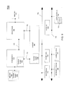
- Multiprocessor system 700 is a point-to-point interconnect system, and includes a first processor 770 and a second processor 780 coupled via a point-to-point interconnect 750 .
- processors 770 and 780 may be multicore processors including, for example, embedded non-volatile memory such as pSTTM described herein.
- First processor 770 may include a memory controller hub (MCH) and point-to-point (P-P) interfaces.
- second processor 780 may include a MCH and P-P interfaces.
- the MCHs may couple the processors to respective memories, namely memory 732 and memory 734 , which may be portions of main memory (e.g., a dynamic random access memory (DRAM) or pSTTM described herein) locally attached to the respective processors.
- main memory e.g., a dynamic random access memory (DRAM) or pSTTM described herein
- the processors may be located on the same chip as memory described herein.
- First processor 770 and second processor 780 may be coupled to a chipset 790 via P-P interconnects, respectively.
- Chipset 790 may include P-P interfaces.
- chipset 790 may be coupled to a first bus 799 via an interface.
- Various input/output (I/O) devices 714 may be coupled to first bus 799 , along with a bus bridge 718 , which couples first bus 799 to a second bus 798 .
- Various devices may be coupled to second bus 798 including, for example, a keyboard/mouse 722 , communication devices 797 , and data storage unit 728 such as a disk drive or other mass storage device, which may include code 730 , in one embodiment. Code may be included in one or more memories including memory 728 , 732 , 734 , memory coupled to system 700 via a network, and the like.
- an audio I/O 724 may be coupled to second bus 798 .
- An Example includes an apparatus comprising: a magnetic tunnel junction (MTJ) including a free magnetic layer, a fixed magnetic layer, and a tunnel barrier between the free and fixed layers; the tunnel barrier directly contacting a first side of the free layer; and an oxide layer directly contacting a second side of the free layer; wherein the tunnel barrier includes an oxide and has a first resistance-area (RA) product and the oxide layer has a second RA product that is lower than the first RA product.
- MTJ magnetic tunnel junction
- RA resistance-area
- the subject matter of the previous examples can optionally include wherein the tunnel barrier includes magnesium oxide and the oxide layer includes at least one of tungsten oxide, vanadium oxide, indium oxide, aluminum oxide, ruthenium oxide, and tantalum oxide.
- the subject matter of the previous examples can optionally include wherein the second RA product is less than 10 mOhm-cm 2 .
- the subject matter of the previous examples can optionally include wherein the second side is primarily located in a plane and the free layer has a thickness, orthogonal to the plane, of less than 2 nm.
- the subject matter of the previous examples can optionally include wherein the tunnel barrier has a thickness less than 3 nm and greater than the thickness of the free layer.
- the subject matter of the previous examples can optionally include wherein the free layer includes cobalt, iron, and boron.
- the subject matter of the previous examples can optionally include perpendicular spin torque transfer memory (STTM) that includes the MTJ.
- STTM perpendicular spin torque transfer memory
- the subject matter of the previous examples can optionally include wherein the second side is in a plane and the free layer has a thickness, orthogonal to the plane, less than a thickness of the tunnel barrier layer.
- the subject matter of the previous examples can optionally include wherein the tunnel barrier includes a first metal and the oxide layer includes a second metal unequal to the first metal.
- the subject matter of the previous examples can optionally include wherein the first side is directly opposite the second side.
- the subject matter of the previous examples can optionally include alternating layers of first and second materials, wherein one of the alternating layers directly contacts the oxide layer opposite where the free layer contacts the oxide layer.
- the subject matter of the previous examples can optionally include wherein the oxide layer, the fixed and free layers, and the tunnel barrier are all thin films.
- the subject matter of the previous examples can optionally include wherein the second RA product is less than 10% of the first RA product.
- the subject matter of the previous examples can optionally include wherein the MTJ has perpendicular anisotropy.
- Another example includes a method comprising: forming a magnetic tunnel junction (MTJ) on a substrate, the MTJ including a free magnetic layer, a fixed magnetic layer, and a tunnel barrier layer between the free and fixed layers; the tunnel barrier directly contacting a first side of the free layer; and forming an oxide layer directly contacting a second side of the free layer; wherein the tunnel barrier has a first resistance-area (RA) product and the oxide layer has a second RA product that is lower than the first RA product.
- MTJ magnetic tunnel junction
- RA resistance-area
- the subject matter of the previous method example can optionally include wherein the oxide layer, the fixed and free layers, and the tunnel barrier are all thin films.
- the subject matter of the previous method examples can optionally include wherein the second side is primarily located in a plane and the free layer has a thickness, orthogonal to the plane, of less than 2 nm and the tunnel barrier layer has a thickness less than 3 nm and greater than the thickness of the free layer.
- the subject matter of the previous method examples can optionally include wherein the second RA product is less than 10% of the first RA product.
- STTM perpendicular spin torque transfer memory
- STTM perpendicular spin torque transfer memory
- MTJ magnetic tunnel junction
- RA resistance-area
- the subject matter of the previous perpendicular STTM example can optionally include wherein the second RA product is less than 10% of the first RA product.
- the subject matter of the previous perpendicular STTM examples can optionally include wherein the oxide layer, the fixed and free layers, and the tunnel barrier are all thin films.
- terms designating relative vertical position refer to a situation where a device side (or active surface) of a substrate or integrated circuit is the “top” surface of that substrate; the substrate may actually be in any orientation so that a “top” side of a substrate may be lower than the “bottom” side in a standard terrestrial frame of reference and still fall within the meaning of the term “top.”
- the term “on” as used herein does not indicate that a first layer “on” a second layer is directly on and in immediate contact with the second layer unless such is specifically stated; there may be a third layer or other structure between the first layer and the second layer on the first layer.
- the embodiments of a device or article described herein can be manufactured, used, or shipped in a number of positions and orientations.
Landscapes
- Engineering & Computer Science (AREA)
- Chemical & Material Sciences (AREA)
- Crystallography & Structural Chemistry (AREA)
- Power Engineering (AREA)
- Computer Hardware Design (AREA)
- Manufacturing & Machinery (AREA)
- Hall/Mr Elements (AREA)
- Mram Or Spin Memory Techniques (AREA)
Abstract
Description
- Embodiments of the invention are in the field of semiconductor devices and, in particular, highly stable spintronic memory.
- Some magnetic memories, such as a spin transfer torque memory (STTM), utilize a magnetic tunnel junction (MTJ) for switching and detection of the memory's magnetic state.
FIG. 1 includes spin transfer torque random access memory (STTRAM), a form of STTM.FIG. 1 includes a MTJ consisting of ferromagnetic (FM)layers Memory 100 is “read” by assessing the change of resistance (e.g., tunneling magnetoresistance (TMR)) for different relative magnetizations ofFM layers - More specifically, MTJ resistance is determined by the relative magnetization directions of
layers Layer 127 is the “reference layer” or “fixed layer” because its magnetization direction is fixed.Layer 125 is the “free layer” because its magnetization direction is changed by passing a driving current polarized by the reference layer (e.g., a positive voltage applied tolayer 127 rotates the magnetization direction oflayer 125 opposite to that oflayer 127 and negative voltage applied tolayer 127 rotates the magnetization direction oflayer 125 to the same direction of layer 127). - Features and advantages of embodiments of the present invention will become apparent from the appended claims, the following detailed description of one or more example embodiments, and the corresponding figures, in which:
-
FIG. 1 depicts a conventional magnetic memory cell. -
FIGS. 2-3 depict conventional MTJs. -
FIG. 4 includes an MTJ portion in an embodiment of the invention. -
FIG. 5 demonstrates how stability increases for an embodiment of the invention. -
FIG. 6 includes an MTJ portion in an embodiment of the invention. -
FIG. 7 includes an MTJ with a multi-layer stack in an embodiment of the invention. -
FIG. 8 includes a memory cell in an embodiment of the invention. -
FIG. 9 depicts a system for use with embodiments of the invention. -
FIG. 10 depicts a method of forming a memory in an embodiment of the invention. - Reference will now be made to the drawings wherein like structures may be provided with like suffix reference designations. In order to show the structures of various embodiments more clearly, the drawings included herein are diagrammatic representations of integrated circuit structures. Thus, the actual appearance of the fabricated integrated circuit structures, for example in a photomicrograph, may appear different while still incorporating the claimed structures of the illustrated embodiments. Moreover, the drawings may only show the structures useful to understand the illustrated embodiments. Additional structures known in the art may not have been included to maintain the clarity of the drawings. “An embodiment”, “various embodiments” and the like indicate embodiment(s) so described may include particular features, structures, or characteristics, but not every embodiment necessarily includes the particular features, structures, or characteristics. Some embodiments may have some, all, or none of the features described for other embodiments. “First”, “second”, “third” and the like describe a common object and indicate different instances of like objects are being referred to. Such adjectives do not imply objects so described must be in a given sequence, either temporally, spatially, in ranking, or in any other manner. “Connected” may indicate elements are in direct physical or electrical contact with each other and “coupled” may indicate elements co-operate or interact with each other, but they may or may not be in direct physical or electrical contact. Also, while similar or same numbers may be used to designate same or similar parts in different figures, doing so does not mean all figures including similar or same numbers constitute a single or same embodiment.
- STTRAM, described above, is just one example of “beyond CMOS” technology (or “non-CMOS based” technology), which relates to devices and processes not entirely implemented with complementary metal-oxide-semiconductor (CMOS) techniques. Beyond CMOS technology may rely on spin polarization (which concerns the degree to which the spin or intrinsic angular momentum of elementary particles is aligned with a given direction) and, more generally, spintronics (a branch of electronics concerning the intrinsic spin of an electron, its associated magnetic moment, and the electron's fundamental electronic charge). Spintronics devices may concern TMR, which uses quantum-mechanical tunneling of electrons through a thin insulator to separate ferromagnetic layers, and STT, where a current of spin polarized electrons may be used to control the magnetization direction of ferromagnetic electrodes.
- Beyond CMOS devices include, for example, spintronics devices implemented in memory (e.g., 3 terminal STTRAM), spin logic devices (e.g., logic gates), tunnel field-effect transistors (TFETs), impact ionization MOS (IMOS) devices, nano-electro-mechanical switches (NEMS), negative common gate FETs, resonant tunneling diodes (RTD), single electron transistors (SET), spin FETs, nanomagnet logic (NML), domain wall logic, domain wall memory, and the like.
- Regarding STTM specifically, one form of STTM includes perpendicular STTM (pSTTM). Where a traditional MTJ or non-perpendicular MTJ generates a magnetization “in plane” (with which “high” and “low” memory states are set), a perpendicular MTJ (pMTJ) generates magnetization “out of plane”. This reduces the switching current needed to switch between high and low memory states. This also allows for better scaling (e.g., smaller size memory cells). Traditional MTJs are converted to pMTJs by, for example, thinning the free layer, thereby making the tunnel barrier/free layer interface more dominant in magnetic field influence (and the interface promotes anisotropic out of plane magnetization). The interface is highlighted with bold dashed lines and Ki in
FIG. 2 (and other figures included herein) which addresses the anisotropic energy at the interface.FIG. 2 includes such a system with CoFeBfree layer 225 interfacingMgO tunnel barrier 226, which further couples to CoFeB fixedlayer 227 and Tantalum (Ta) contacts 214 (which may couple to a selection switch such astransistor 120 ofFIG. 1 ), 216 (which may couple, by way of one or more vias, to a bit line such asbit line 105 ofFIG. 1 ). -
FIG. 3 depicts a MTJ, where a second oxidizedMgO interface 320 contacts CoFeB free layer 325 (which further couples to atunnel barrier MgO 326, which is formed on CoFeB fixed layer 327). Doing so may increase stability for the memory, which is a problem for devices such as the device ofFIG. 2 . Thus,FIG. 3 includes MgO at both free layer interfaces (i.e.,layers 320, 326). However, introducingMgO layer 320 on top of CoFeBfree layer 325 increases total resistance significantly (as compared to having just one oxide layer interface the free layer as inFIG. 2 ), which makes the design impractical for scaled devices (e.g., 22 nm) because of degradation in resistance-area (RA) product and TMR. In other words, ifMgO layer 326 is predominately responsible for resistance and voltage drop in conventional MTJs, adding yet another layer of MgO in series withlayer 326 increases RA product, thereby driving up write voltage, decreasing battery life, and the like. - RA product refers to a measurement unequal to resistivity. Resistivity has units in ohm-cm, whereas RA product=ρTMgO/A*A∝TMgO, with units in ohm-um2 (ρ represents the material resistivity, A represents the dot area, and TMgO represents the MgO thickness). While resistivity represents an “inherent resistance” and is independent of the thickness of a material layer, RA product is directly proportional to the thickness of the material. (Regarding “thickness”,
layer 320 is disposed “horizontally” for purposes of discussion herein and has a “thickness” in the vertical orientation. The length and width forlayer 320 are “in plane” and the height or thickness is “out of plane”.) - Thus, returning to
FIG. 3 , a higher RA product increases STTM resistance. While this does not necessarily increase write current, a higher RA product does increase write voltage (write voltage=Jc * RA product) (Jc refers to a critical switching current density to write a bit). Also, a larger STTM resistance degrades current provided by a select transistor (e.g.,MOS transistor 120 ofFIG. 1 ) since the Gate-to-Source voltage is smaller due to the larger IR drop across the STTM resistance. -
FIG. 4 differs fromFIG. 3 , however, and includes an MTJ portion in an embodiment of the invention having an oxidized layer that includes tantalum oxide (TaO)interface 420. This increases stability for the device without increasing RA product too much.Layer 420 contacts Co20Fe60B20free layer 425, which further couples toMgO layer 426, a substrate (layer 414), and other layers not necessarily shown. (The stack inFIG. 4 was used to generate the EHE data ofFIG. 5 , which is discussed below. No fixed layer is included in the stack in order to better focus on the EHE effects of adding the second oxide on the free layer. The presence of the fixed layer would not have aided in generating the data ofFIG. 5 .) “Second oxide film” 420 (i.e., a second oxide film in addition to tunnel barrier, which constitutes a “first oxide film”) enhances thermal stability (strength) offree layer 425, thereby decreasing the odds of faulty high/low or low/high memory state conversions. The insertion ofoxide layer 420 may be included with CoFeBfree film 425, which could have already been thinned to further promote anisotropic magnetic properties for the pSTTM. - For example,
layer 425 is primarily located in the horizontal plane andfree layer 425 has a thickness, orthogonal to the plane (vertical dimension), of less than 2 nm whileoxide layer 426 has a thickness less than 3 nm (and greater than the thickness of free layer 425). In anembodiment layer 426 may include a thickness of about 1 nm, with an RA product of about 10 ohm-um2.Layer 426 thickness may be thicker or thinner (and consequently RA product can vary around 10 ohm-um2 as well) in other embodiments. Some embodiments may include a 2-3 nmthick layer 426.Free layer 425 thickness may be around 1-2 nm, but other embodiments are not so limited.Layer 420 may vary accordingly to gain an RA product much less than the RA product of layer 426 (e.g., so series resistance addition is negligible or low). For example, an embodiment may include an RA product of 10 ohm-um2 for layer 426 (e.g., MgO) and anRA product 10× lower forlayer 420 so the effect oflayer 420 on electrical resistance is much smaller than that oflayer 426. These same dimensions are applicable to other embodiments described herein (e.g.,FIG. 6 ) and are not limiting on all embodiments. - Thus,
FIG. 4 is an example of a more general concept for embodiments of the invention whereby a high conductivity oxide, such aslayer 420, is formed next to an interface of CoFeBfree layer 425. This induces large stability without unnecessarily degrading RA product and TMR (as is the case with the dual MgO layers found inFIG. 3 ). In other words, this induces greater stability without overly increasing RA product (which may adversely affect write/read voltages) or diminishing TMR (which may complicate accurate reads of memory states). The other interface to CoFeBfree layer 425 is MgO spin filter 426 (i.e., tunnel barrier). -
FIG. 5 demonstrates stability increases for the embodiment ofFIG. 4 .FIG. 5 concerns a free layer connected to tantalum (Ta) and a tunnel barrier (see circle plot points) compared to a free layer connected to tantalum oxide (TaO) and a tunnel barrier (see square plot points). In the unoxidized case (circle plot points) there is a Ruthenium (Ru) cap above the Ta. The narrow gap for the tunnel barrier/free layer/Ta/Ru arrangement has a very narrow horizontal band that shows a quick Extraordinary Hall Effect (EHE) transition over a short magnetic field deviation (indicating low stability or coercivity). In contrast, the broader horizontal gap for the tunnel barrier/free layer/TaO arrangement has a broader band that shows a more tolerant EHE transition over a broader magnetic field deviation (indicating higher stability or coercivity). As shown inFIG. 5 , the barrier/free layer/TaO arrangement has a 4× coercivity improvement over the tunnel barrier/free layer/Ta/Ru arrangement. - This second oxidized interface (interface between
layers 425, 420) can be designed with an RA product much lower than the RA product for the tunnel barrier. Thus, a high-conductivity oxide (i.e., lower RA product) on top of a free layer can lead to greater stability. Embodiments provide the conductive oxide oflayer 420 may be 100-1000× less conductive than the tunnel barrier. For example, tunnel barrier MgO may have a resistivity of about 1 ohm-cm. In contrast, the high conductivity oxide may include, for example, any one or more of the following: tungsten oxide (WO2), vanadium oxide (VO and/or V2O2), indium oxide (InOx), aluminum oxide (Al2O3), ruthenium oxide (RuOx), and/or TaO. For example, In2O3 includes a tunable resistivity of 1-10 mOhm-cm, VO2 and V2O3 include resistivity less that 1 mOhm-cm, WO2 includes resistivity less than 1 mOhm-cm, and tin (Sn) doped In2O3 (ITO) includes resistivity less than 0.1 mOhm-cm. -
FIG. 6 showssecond barrier 620 placed betweenCoFeB 625 andTa contact 616.Free layer 625 is ontunnel barrier 626 and fixedlayer 627. -
FIG. 7 showssecond oxide barrier 720 placed betweenCoFeB 725 and amulti-layer arrangement 713 including alternating Cobalt (Co) and Palladium (Pd) layers that help enhance stability for the small film MTJ.Second oxide barrier 720 may be adjacent thinned CoFeBfree layer 725, which interfaces first oxide layer MgO spin filter 726 (which is on fixedlayer 727 and below Ta contact layer 716). Thinned CoFeBfree layer 725 provides a layer with strong spin-orbit coupling to render perpendicular anisotropy. - Thus, various embodiments introduce a second oxidized layer next to the free layer, which enhances stability through dual oxidized interfaces (on top and bottom of the free layer) without adversely affecting RA product or TMR (i.e., overly increasing RA product or overly diminishing TMR). Accordingly, the second oxidized layer has a low RA product as compared to the tunnel barrier. Some embodiments include this second oxidized layer with a free layer and a multi-layer stack.
-
FIG. 8 includes a memory cell in an embodiment of the invention. The memory cell includes a 1T-1X (T=transistor, X=capacitor or resistor) at a small cell size. The MTJ comprises fixed/free layers tunnel barrier 826, andoxide layer 820. The MTJ couples bitline 805 to selection switch 821 (e.g., transistor),word line 810, andsense line 815. The MTJ may be located on a substrate. - In an embodiment, the substrate is a bulk semiconductive material as part of a wafer. In an embodiment, the semiconductive substrate is a bulk semiconductive material as part of a chip that has been singulated from a wafer. In an embodiment, the semiconductive substrate is a semiconductive material that is formed above an insulator such as a semiconductor on insulator (SOI) substrate. In an embodiment, the semiconductive substrate is a prominent structure such as a fin that extends above a bulk semiconductive material. There may be one or more layers between the MTJ and the substrate. There may be one or more layers above the MTJ.
- An embodiment includes a method 1000 of forming an apparatus (
FIG. 10 ). In block 1005 a fixed layer of a MTJ is formed over a substrate. In block 1010 a tunnel barrier (first oxide layer) is formed over the fixed layer. In block 1015 a free layer is formed over the tunnel barrier. Inblock 1020 an oxidized layer (second oxide layer) is formed on the free layer. The free and fixed layers, the tunnel barrier, and the oxidized layer are all thin films (a layer less than several micrometers in thickness). In an embodiment there is no vacuum break between the CoFeB formation and second oxide deposition. A vacuum break may lead to uncontrollable oxidation/degradation of the thin CoFeB. Thus, the entire stack is deposited in-situ (without vacuum breaks) in an embodiment. - While several embodiments herein describe perpendicular STTM, other embodiments are not so limited and may concern in plane (non-perpendicular) STTM, as well as embodiments that are neither fully in plane (non-perpendicular) or fully out of plane (perpendicular) but are instead something in between in plane and out of plane.
- At times herein a first oxide layer is said to “directly contact” the tunnel barrier layer and/or a first side of the free layer; and a second oxide layer “directly contacts” a second side of the free layer. This includes situations where one considers, for example, an oxide layer to be a sublayer of either the tunnel barrier and/or the free layer. This includes situations where one considers, for example, an oxide layer to be some or all of the tunnel barrier. Further, the tunnel barrier may include oxide but may further include further oxidation at its surface/interface to the free layer. Such a situation would still comprise an oxide layer contacting both the free layer and the tunnel barrier. Further, for example, there can be some oxidation of the CoFeB layer during the formation of the second metal oxide.
- In an embodiment the metal oxide (second oxide layer) is directly in contact with the second side (e.g., upper side) of the free layer. The contact create an interface anisotropy (represented by Ki in the figures), which adds to the thermal stability of the CoFeB free layer.
- While several embodiments include fixed and free layers comprising CoFeB, other embodiments may include CoFe/CoFeB; CoFeB/Ta/CoFeB; or CoFe/CoFeB/Ta/CoFeB/CoFe. Further, other embodiments may include tunnel barriers having something other than MgO, such as other oxides.
- Embodiments may be used in many different types of systems. For example, in one embodiment a communication device (e.g., cell phone, Smartphone, netbook, notebook, personal computer, watch, and camera) can be arranged to include various embodiments described herein. Referring now to
FIG. 9 , shown is a block diagram of a system in accordance with an embodiment of the present invention.Multiprocessor system 700 is a point-to-point interconnect system, and includes afirst processor 770 and asecond processor 780 coupled via a point-to-point interconnect 750. Each ofprocessors First processor 770 may include a memory controller hub (MCH) and point-to-point (P-P) interfaces. Similarly,second processor 780 may include a MCH and P-P interfaces. The MCHs may couple the processors to respective memories, namelymemory 732 andmemory 734, which may be portions of main memory (e.g., a dynamic random access memory (DRAM) or pSTTM described herein) locally attached to the respective processors. However, the processors may be located on the same chip as memory described herein.First processor 770 andsecond processor 780 may be coupled to achipset 790 via P-P interconnects, respectively.Chipset 790 may include P-P interfaces. Furthermore,chipset 790 may be coupled to afirst bus 799 via an interface. Various input/output (I/O)devices 714 may be coupled tofirst bus 799, along with a bus bridge 718, which couplesfirst bus 799 to asecond bus 798. Various devices may be coupled tosecond bus 798 including, for example, a keyboard/mouse 722,communication devices 797, anddata storage unit 728 such as a disk drive or other mass storage device, which may includecode 730, in one embodiment. Code may be included in one or morememories including memory system 700 via a network, and the like. Further, an audio I/O 724 may be coupled tosecond bus 798. - The following examples pertain to further embodiments.
- An Example includes an apparatus comprising: a magnetic tunnel junction (MTJ) including a free magnetic layer, a fixed magnetic layer, and a tunnel barrier between the free and fixed layers; the tunnel barrier directly contacting a first side of the free layer; and an oxide layer directly contacting a second side of the free layer; wherein the tunnel barrier includes an oxide and has a first resistance-area (RA) product and the oxide layer has a second RA product that is lower than the first RA product.
- In another example, the subject matter of the previous examples can optionally include wherein the tunnel barrier includes magnesium oxide and the oxide layer includes at least one of tungsten oxide, vanadium oxide, indium oxide, aluminum oxide, ruthenium oxide, and tantalum oxide.
- In another example, the subject matter of the previous examples can optionally include wherein the second RA product is less than 10 mOhm-cm2.
- In another example, the subject matter of the previous examples can optionally include wherein the second side is primarily located in a plane and the free layer has a thickness, orthogonal to the plane, of less than 2 nm.
- In another example, the subject matter of the previous examples can optionally include wherein the tunnel barrier has a thickness less than 3 nm and greater than the thickness of the free layer.
- In another example, the subject matter of the previous examples can optionally include wherein the free layer includes cobalt, iron, and boron.
- In another example, the subject matter of the previous examples can optionally include perpendicular spin torque transfer memory (STTM) that includes the MTJ.
- In another example, the subject matter of the previous examples can optionally include wherein the second side is in a plane and the free layer has a thickness, orthogonal to the plane, less than a thickness of the tunnel barrier layer.
- In another example, the subject matter of the previous examples can optionally include wherein the tunnel barrier includes a first metal and the oxide layer includes a second metal unequal to the first metal.
- In another example, the subject matter of the previous examples can optionally include wherein the first side is directly opposite the second side.
- In another example, the subject matter of the previous examples can optionally include alternating layers of first and second materials, wherein one of the alternating layers directly contacts the oxide layer opposite where the free layer contacts the oxide layer.
- In another example, the subject matter of the previous examples can optionally include wherein the oxide layer, the fixed and free layers, and the tunnel barrier are all thin films.
- In another example, the subject matter of the previous examples can optionally include wherein the second RA product is less than 10% of the first RA product.
- In another example, the subject matter of the previous examples can optionally include wherein the MTJ has perpendicular anisotropy.
- Another example includes a method comprising: forming a magnetic tunnel junction (MTJ) on a substrate, the MTJ including a free magnetic layer, a fixed magnetic layer, and a tunnel barrier layer between the free and fixed layers; the tunnel barrier directly contacting a first side of the free layer; and forming an oxide layer directly contacting a second side of the free layer; wherein the tunnel barrier has a first resistance-area (RA) product and the oxide layer has a second RA product that is lower than the first RA product.
- In another example, the subject matter of the previous method example can optionally include wherein the oxide layer, the fixed and free layers, and the tunnel barrier are all thin films.
- In another example, the subject matter of the previous method examples can optionally include wherein the second side is primarily located in a plane and the free layer has a thickness, orthogonal to the plane, of less than 2 nm and the tunnel barrier layer has a thickness less than 3 nm and greater than the thickness of the free layer.
- In another example, the subject matter of the previous method examples can optionally include wherein the second RA product is less than 10% of the first RA product.
- Another example includes a perpendicular spin torque transfer memory (STTM) comprising:a magnetic tunnel junction (MTJ) including a tunnel barrier layer between free and fixed layers and directly contacting a side of the free layer; and an oxide layer directly contacting an opposing side of the free layer; wherein the tunnel barrier has a first resistance-area (RA) product and the oxide layer has a second RA product that is lower than the first RA product.
- In another example, the subject matter of the previous perpendicular STTM example can optionally include wherein the second RA product is less than 10% of the first RA product.
- In another example, the subject matter of the previous perpendicular STTM examples can optionally include wherein the oxide layer, the fixed and free layers, and the tunnel barrier are all thin films.
- The foregoing description of the embodiments of the invention has been presented for the purposes of illustration and description. It is not intended to be exhaustive or to limit the invention to the precise forms disclosed. This description and the claims following include terms, such as left, right, top, bottom, over, under, upper, lower, first, second, etc. that are used for descriptive purposes only and are not to be construed as limiting. For example, terms designating relative vertical position refer to a situation where a device side (or active surface) of a substrate or integrated circuit is the “top” surface of that substrate; the substrate may actually be in any orientation so that a “top” side of a substrate may be lower than the “bottom” side in a standard terrestrial frame of reference and still fall within the meaning of the term “top.” The term “on” as used herein (including in the claims) does not indicate that a first layer “on” a second layer is directly on and in immediate contact with the second layer unless such is specifically stated; there may be a third layer or other structure between the first layer and the second layer on the first layer. The embodiments of a device or article described herein can be manufactured, used, or shipped in a number of positions and orientations. Persons skilled in the relevant art can appreciate that many modifications and variations are possible in light of the above teaching. Persons skilled in the art will recognize various equivalent combinations and substitutions for various components shown in the Figures. It is therefore intended that the scope of the invention be limited not by this detailed description, but rather by the claims appended hereto.
Claims (21)
Priority Applications (1)
| Application Number | Priority Date | Filing Date | Title |
|---|---|---|---|
| US14/982,128 US9735348B2 (en) | 2013-03-28 | 2015-12-29 | High stability spintronic memory |
Applications Claiming Priority (1)
| Application Number | Priority Date | Filing Date | Title |
|---|---|---|---|
| PCT/US2013/034506 WO2014158178A1 (en) | 2013-03-28 | 2013-03-28 | High stability spintronic memory |
Related Parent Applications (1)
| Application Number | Title | Priority Date | Filing Date |
|---|---|---|---|
| PCT/US2013/034506 A-371-Of-International WO2014158178A1 (en) | 2013-03-28 | 2013-03-28 | High stability spintronic memory |
Related Child Applications (1)
| Application Number | Title | Priority Date | Filing Date |
|---|---|---|---|
| US14/982,128 Continuation US9735348B2 (en) | 2013-03-28 | 2015-12-29 | High stability spintronic memory |
Publications (2)
| Publication Number | Publication Date |
|---|---|
| US20140291663A1 true US20140291663A1 (en) | 2014-10-02 |
| US9231194B2 US9231194B2 (en) | 2016-01-05 |
Family
ID=51619925
Family Applications (2)
| Application Number | Title | Priority Date | Filing Date |
|---|---|---|---|
| US13/996,603 Expired - Fee Related US9231194B2 (en) | 2013-03-28 | 2013-03-28 | High stability spintronic memory |
| US14/982,128 Active US9735348B2 (en) | 2013-03-28 | 2015-12-29 | High stability spintronic memory |
Family Applications After (1)
| Application Number | Title | Priority Date | Filing Date |
|---|---|---|---|
| US14/982,128 Active US9735348B2 (en) | 2013-03-28 | 2015-12-29 | High stability spintronic memory |
Country Status (8)
| Country | Link |
|---|---|
| US (2) | US9231194B2 (en) |
| JP (1) | JP6195974B2 (en) |
| KR (1) | KR102076086B1 (en) |
| CN (1) | CN105308683B (en) |
| DE (1) | DE112013006657T5 (en) |
| GB (1) | GB2526958B (en) |
| TW (1) | TWI608641B (en) |
| WO (1) | WO2014158178A1 (en) |
Cited By (15)
| Publication number | Priority date | Publication date | Assignee | Title |
|---|---|---|---|---|
| US9300295B1 (en) | 2014-10-30 | 2016-03-29 | Qualcomm Incorporated | Elimination of undesirable current paths in GSHE-MTJ based circuits |
| CN107328898A (en) * | 2017-07-18 | 2017-11-07 | 招商局重庆交通科研设计院有限公司 | Pass through tomography tunnel excavation analogue experiment installation |
| US9905753B2 (en) | 2015-09-17 | 2018-02-27 | Samsung Electronics Co., Ltd. | Free layer, magnetoresistive cell, and magnetoresistive random access memory device having low boron concentration region and high boron concentration region, and methods of fabricating the same |
| US9966529B1 (en) * | 2017-03-17 | 2018-05-08 | Headway Technologies, Inc. | MgO insertion into free layer for magnetic memory applications |
| CN108140724A (en) * | 2015-11-23 | 2018-06-08 | 英特尔公司 | Electrical contacts for magnetoresistive random access memory devices |
| US10243021B1 (en) * | 2017-12-27 | 2019-03-26 | Spin Memory, Inc. | Steep slope field-effect transistor (FET) for a perpendicular magnetic tunnel junction (PMTJ) |
| US10255186B2 (en) * | 2017-06-14 | 2019-04-09 | Purdue Research Foundation | Approximate cache memory |
| WO2019074945A1 (en) * | 2017-10-10 | 2019-04-18 | Headway Technologies, Inc. | High thermal stability by doping of oxide capping layer for spin torque transfer (stt) magnetic random access memory (mram) applications |
| US10355046B1 (en) | 2017-12-29 | 2019-07-16 | Spin Memory, Inc. | Steep slope field-effect transistor (FET) for a perpendicular magnetic tunnel junction (PMTJ) |
| US10446740B2 (en) * | 2015-03-31 | 2019-10-15 | Tdk Corporation | Magnetoresistance effect element |
| US11133028B2 (en) | 2015-03-31 | 2021-09-28 | Tdk Corporation | Magnetoresistance effect element |
| CN114689090A (en) * | 2022-03-28 | 2022-07-01 | 杭州电子科技大学 | Self-adaptive compensation method and circuit for Hall bar array output bias |
| US11495738B2 (en) * | 2018-08-07 | 2022-11-08 | Taiwan Semiconductor Manufacturing Company, Ltd | Dual magnetic tunnel junction devices for magnetic random access memory (MRAM) |
| US11683994B2 (en) | 2019-06-21 | 2023-06-20 | Headway Technologies, Inc. | Magnetic element with perpendicular magnetic anisotropy (PMA) and improved coercivity field (Hc)/switching current ratio |
| US12550623B2 (en) | 2019-02-14 | 2026-02-10 | Headway Technologies, Inc. | Nitride diffusion barrier structure for spintronic applications |
Families Citing this family (13)
| Publication number | Priority date | Publication date | Assignee | Title |
|---|---|---|---|---|
| CN105493292B (en) * | 2013-09-30 | 2019-09-06 | 英特尔公司 | spintronic logic element |
| CN107636851B (en) * | 2015-06-26 | 2022-02-01 | 英特尔公司 | Perpendicular magnetic memory with symmetric fixed layer |
| KR102511914B1 (en) | 2016-08-04 | 2023-03-21 | 삼성전자주식회사 | Magnetic memory device and method for manufacturing the same |
| CN106409961B (en) * | 2016-11-23 | 2018-06-29 | 常熟理工学院 | n-Si/CdSSe laminated solar cell and preparation method thereof |
| EP3563432A4 (en) * | 2016-12-28 | 2020-07-08 | INTEL Corporation | MAGNETIC MECHANISM WITH VERTICAL SPINDLE TORQUE |
| WO2018182642A1 (en) * | 2017-03-30 | 2018-10-04 | Intel Corporation | Spintronic memory with low resistance cap layer |
| WO2018182644A1 (en) * | 2017-03-30 | 2018-10-04 | Intel Corporation | Spintronic memory with low oxygen precipitation |
| WO2018182663A1 (en) * | 2017-03-31 | 2018-10-04 | Intel Corporation | Spintronic memory with metal oxide cap layer |
| JP6832818B2 (en) | 2017-09-21 | 2021-02-24 | キオクシア株式会社 | Magnetic storage device |
| US10833255B2 (en) * | 2017-09-21 | 2020-11-10 | Hitachi High-Tech Corporation | Method for manufacturing magnetic tunnel junction element, and inductively coupled plasma processing apparatus |
| CN109904291B (en) * | 2019-02-13 | 2021-09-28 | 湖北大学 | Spinning electronic device and preparation method and regulation and control method thereof |
| WO2021163908A1 (en) | 2020-02-19 | 2021-08-26 | Yangtze Memory Technologies Co., Ltd. | Magnetic memory structure and device |
| DE112022003362T5 (en) * | 2021-07-01 | 2024-05-02 | Sony Semiconductor Solutions Corporation | MAGNETIC MEMORY ELEMENT AND SEMICONDUCTOR DEVICE |
Citations (10)
| Publication number | Priority date | Publication date | Assignee | Title |
|---|---|---|---|---|
| US20120205758A1 (en) * | 2011-02-11 | 2012-08-16 | Magic Technologies, Inc. | Magnetic element with improved out-of-plane anisotropy for spintronic applications |
| US8279666B2 (en) * | 2009-05-27 | 2012-10-02 | Institut Polytechnique De Grenoble | Spin polarised magnetic device |
| US20120280336A1 (en) * | 2011-05-04 | 2012-11-08 | Magic Technologies, Inc. | Multilayers having reduced perpendicular demagnetizing field using moment dilution for spintronic applications |
| US20130230741A1 (en) * | 2012-03-01 | 2013-09-05 | Headway Technologies, Inc. | High Thermal Stability Free Layer with High Out-of-Plane Anisotropy for Magnetic Device Applications |
| US20130307097A1 (en) * | 2012-05-15 | 2013-11-21 | Ge Yi | Magnetoresistive random access memory cell design |
| US8611139B2 (en) * | 2010-09-14 | 2013-12-17 | Sony Corporation | Memory element and memory device |
| US20140001586A1 (en) * | 2012-06-28 | 2014-01-02 | Industrial Technology Research Institute | Perpendicularly magnetized magnetic tunnel junction device |
| US20140021426A1 (en) * | 2012-07-17 | 2014-01-23 | Yun-Jae Lee | Magnetic device and method of manufacturing the same |
| US20140061828A1 (en) * | 2012-08-30 | 2014-03-06 | Woo Chang Lim | Magnetic memory devices |
| US8796797B2 (en) * | 2012-12-21 | 2014-08-05 | Intel Corporation | Perpendicular spin transfer torque memory (STTM) device with enhanced stability and method to form same |
Family Cites Families (14)
| Publication number | Priority date | Publication date | Assignee | Title |
|---|---|---|---|---|
| JP2006165265A (en) * | 2004-12-07 | 2006-06-22 | Sony Corp | Memory element and memory |
| US8374025B1 (en) * | 2007-02-12 | 2013-02-12 | Avalanche Technology, Inc. | Spin-transfer torque magnetic random access memory (STTMRAM) with laminated free layer |
| WO2008154519A1 (en) * | 2007-06-12 | 2008-12-18 | Grandis, Inc. | Method and system for providing a magnetic element and magnetic memory being unidirectional writing enabled |
| JP4738395B2 (en) * | 2007-09-25 | 2011-08-03 | 株式会社東芝 | Magnetoresistive element and magnetic random access memory using the same |
| US8039913B2 (en) * | 2008-10-09 | 2011-10-18 | Seagate Technology Llc | Magnetic stack with laminated layer |
| CN102246327B (en) * | 2008-12-10 | 2013-11-27 | 株式会社日立制作所 | Magnetoresistance effect element and magnetic memory cell and magnetic random access memory using same |
| US20110031569A1 (en) * | 2009-08-10 | 2011-02-10 | Grandis, Inc. | Method and system for providing magnetic tunneling junction elements having improved performance through capping layer induced perpendicular anisotropy and memories using such magnetic elements |
| US8445979B2 (en) * | 2009-09-11 | 2013-05-21 | Samsung Electronics Co., Ltd. | Magnetic memory devices including magnetic layers separated by tunnel barriers |
| US8558331B2 (en) * | 2009-12-08 | 2013-10-15 | Qualcomm Incorporated | Magnetic tunnel junction device |
| US8604572B2 (en) * | 2010-06-14 | 2013-12-10 | Regents Of The University Of Minnesota | Magnetic tunnel junction device |
| JP2012238631A (en) | 2011-05-10 | 2012-12-06 | Sony Corp | Memory element and memory device |
| US8686484B2 (en) | 2011-06-10 | 2014-04-01 | Everspin Technologies, Inc. | Spin-torque magnetoresistive memory element and method of fabricating same |
| US20130001717A1 (en) * | 2011-07-01 | 2013-01-03 | Yuchen Zhou | Perpendicular mram with mtj including laminated magnetic layers |
| US8592929B2 (en) * | 2011-09-12 | 2013-11-26 | Qualcomm Incorporated | Symmetrically switchable spin-transfer-torque magnetoresistive device |
-
2013
- 2013-03-28 WO PCT/US2013/034506 patent/WO2014158178A1/en not_active Ceased
- 2013-03-28 GB GB1514054.4A patent/GB2526958B/en active Active
- 2013-03-28 DE DE112013006657.2T patent/DE112013006657T5/en not_active Withdrawn
- 2013-03-28 CN CN201380074016.0A patent/CN105308683B/en not_active Expired - Fee Related
- 2013-03-28 KR KR1020157022420A patent/KR102076086B1/en active Active
- 2013-03-28 JP JP2016505444A patent/JP6195974B2/en active Active
- 2013-03-28 US US13/996,603 patent/US9231194B2/en not_active Expired - Fee Related
-
2014
- 2014-03-24 TW TW103110902A patent/TWI608641B/en active
-
2015
- 2015-12-29 US US14/982,128 patent/US9735348B2/en active Active
Patent Citations (10)
| Publication number | Priority date | Publication date | Assignee | Title |
|---|---|---|---|---|
| US8279666B2 (en) * | 2009-05-27 | 2012-10-02 | Institut Polytechnique De Grenoble | Spin polarised magnetic device |
| US8611139B2 (en) * | 2010-09-14 | 2013-12-17 | Sony Corporation | Memory element and memory device |
| US20120205758A1 (en) * | 2011-02-11 | 2012-08-16 | Magic Technologies, Inc. | Magnetic element with improved out-of-plane anisotropy for spintronic applications |
| US20120280336A1 (en) * | 2011-05-04 | 2012-11-08 | Magic Technologies, Inc. | Multilayers having reduced perpendicular demagnetizing field using moment dilution for spintronic applications |
| US20130230741A1 (en) * | 2012-03-01 | 2013-09-05 | Headway Technologies, Inc. | High Thermal Stability Free Layer with High Out-of-Plane Anisotropy for Magnetic Device Applications |
| US20130307097A1 (en) * | 2012-05-15 | 2013-11-21 | Ge Yi | Magnetoresistive random access memory cell design |
| US20140001586A1 (en) * | 2012-06-28 | 2014-01-02 | Industrial Technology Research Institute | Perpendicularly magnetized magnetic tunnel junction device |
| US20140021426A1 (en) * | 2012-07-17 | 2014-01-23 | Yun-Jae Lee | Magnetic device and method of manufacturing the same |
| US20140061828A1 (en) * | 2012-08-30 | 2014-03-06 | Woo Chang Lim | Magnetic memory devices |
| US8796797B2 (en) * | 2012-12-21 | 2014-08-05 | Intel Corporation | Perpendicular spin transfer torque memory (STTM) device with enhanced stability and method to form same |
Cited By (24)
| Publication number | Priority date | Publication date | Assignee | Title |
|---|---|---|---|---|
| US9300295B1 (en) | 2014-10-30 | 2016-03-29 | Qualcomm Incorporated | Elimination of undesirable current paths in GSHE-MTJ based circuits |
| US10446740B2 (en) * | 2015-03-31 | 2019-10-15 | Tdk Corporation | Magnetoresistance effect element |
| US12211524B2 (en) | 2015-03-31 | 2025-01-28 | Tdk Corporation | Magnetoresistance effect element |
| US11871681B2 (en) | 2015-03-31 | 2024-01-09 | Tdk Corporation | Magnetoresistance effect element |
| US11763841B2 (en) | 2015-03-31 | 2023-09-19 | Tdk Corporation | Magnetoresistance effect element |
| US11600771B2 (en) | 2015-03-31 | 2023-03-07 | Tdk Corporation | Magnetoresistance effect element |
| US11133028B2 (en) | 2015-03-31 | 2021-09-28 | Tdk Corporation | Magnetoresistance effect element |
| US11056642B2 (en) | 2015-03-31 | 2021-07-06 | Tdk Corporation | Magnetoresistance effect element |
| US9905753B2 (en) | 2015-09-17 | 2018-02-27 | Samsung Electronics Co., Ltd. | Free layer, magnetoresistive cell, and magnetoresistive random access memory device having low boron concentration region and high boron concentration region, and methods of fabricating the same |
| US10147873B2 (en) | 2015-09-17 | 2018-12-04 | Samsung Electronics Co., Ltd. | Free layer, magnetoresistive cell, and magnetoresistive random access memory device having low boron concentration region and high boron concentration region, and methods of fabricating the same |
| CN108140724A (en) * | 2015-11-23 | 2018-06-08 | 英特尔公司 | Electrical contacts for magnetoresistive random access memory devices |
| US10411068B2 (en) * | 2015-11-23 | 2019-09-10 | Intel Corporation | Electrical contacts for magnetoresistive random access memory devices |
| US10193062B2 (en) * | 2017-03-17 | 2019-01-29 | Headway Technologies, Inc. | MgO insertion into free layer for magnetic memory applications |
| US9966529B1 (en) * | 2017-03-17 | 2018-05-08 | Headway Technologies, Inc. | MgO insertion into free layer for magnetic memory applications |
| US10255186B2 (en) * | 2017-06-14 | 2019-04-09 | Purdue Research Foundation | Approximate cache memory |
| CN107328898A (en) * | 2017-07-18 | 2017-11-07 | 招商局重庆交通科研设计院有限公司 | Pass through tomography tunnel excavation analogue experiment installation |
| WO2019074945A1 (en) * | 2017-10-10 | 2019-04-18 | Headway Technologies, Inc. | High thermal stability by doping of oxide capping layer for spin torque transfer (stt) magnetic random access memory (mram) applications |
| DE112018005549B4 (en) * | 2017-10-10 | 2024-03-14 | Taiwan Semiconductor Manufacturing Company, Ltd. | HIGH THERMAL STABILITY THROUGH DOPING OF OXIDE COVER LAYER FOR MAGNETIC RANDOM ACCESS MEMORY (MRAM) APPLICATIONS WITH SPINNING TORQUE TRANSFER (STT) |
| US10243021B1 (en) * | 2017-12-27 | 2019-03-26 | Spin Memory, Inc. | Steep slope field-effect transistor (FET) for a perpendicular magnetic tunnel junction (PMTJ) |
| US10355046B1 (en) | 2017-12-29 | 2019-07-16 | Spin Memory, Inc. | Steep slope field-effect transistor (FET) for a perpendicular magnetic tunnel junction (PMTJ) |
| US11495738B2 (en) * | 2018-08-07 | 2022-11-08 | Taiwan Semiconductor Manufacturing Company, Ltd | Dual magnetic tunnel junction devices for magnetic random access memory (MRAM) |
| US12550623B2 (en) | 2019-02-14 | 2026-02-10 | Headway Technologies, Inc. | Nitride diffusion barrier structure for spintronic applications |
| US11683994B2 (en) | 2019-06-21 | 2023-06-20 | Headway Technologies, Inc. | Magnetic element with perpendicular magnetic anisotropy (PMA) and improved coercivity field (Hc)/switching current ratio |
| CN114689090A (en) * | 2022-03-28 | 2022-07-01 | 杭州电子科技大学 | Self-adaptive compensation method and circuit for Hall bar array output bias |
Also Published As
| Publication number | Publication date |
|---|---|
| KR102076086B1 (en) | 2020-02-11 |
| JP2016518021A (en) | 2016-06-20 |
| KR20150136055A (en) | 2015-12-04 |
| US9231194B2 (en) | 2016-01-05 |
| US9735348B2 (en) | 2017-08-15 |
| JP6195974B2 (en) | 2017-09-13 |
| TWI608641B (en) | 2017-12-11 |
| CN105308683B (en) | 2018-03-13 |
| US20160133829A1 (en) | 2016-05-12 |
| GB201514054D0 (en) | 2015-09-23 |
| WO2014158178A1 (en) | 2014-10-02 |
| DE112013006657T5 (en) | 2015-11-26 |
| GB2526958B (en) | 2020-11-18 |
| CN105308683A (en) | 2016-02-03 |
| GB2526958A (en) | 2015-12-09 |
| TW201507223A (en) | 2015-02-16 |
Similar Documents
| Publication | Publication Date | Title |
|---|---|---|
| US9735348B2 (en) | High stability spintronic memory | |
| US10068946B2 (en) | Magnetic memory | |
| CN106374035B (en) | Use the voltage-controlled magnetic anisotropy switching device of external ferromagnetic bias film | |
| US11309488B2 (en) | Double spin filter tunnel junction | |
| US8786040B2 (en) | Perpendicular spin transfer torque memory (STTM) device having offset cells and method to form same | |
| US9559698B2 (en) | Spintronic logic element | |
| TWI791133B (en) | Spin-orbit-torque magnetic device and method of fabricating the same | |
| US11081153B2 (en) | Magnetic memory device with balancing synthetic anti-ferromagnetic layer | |
| US11373915B2 (en) | Tunnel magnetoresistive effect element, magnetic memory, and built-in memory | |
| KR20170066320A (en) | Magnetic diffusion barriers and filter in psttm mtj construction | |
| US10340443B2 (en) | Perpendicular magnetic memory with filament conduction path | |
| JP6449392B2 (en) | Apparatus, method and memory | |
| WO2018182644A1 (en) | Spintronic memory with low oxygen precipitation | |
| WO2018182645A1 (en) | Spintronic memory with perforated cap layer | |
| WO2018182642A1 (en) | Spintronic memory with low resistance cap layer |
Legal Events
| Date | Code | Title | Description |
|---|---|---|---|
| FEPP | Fee payment procedure |
Free format text: PAYOR NUMBER ASSIGNED (ORIGINAL EVENT CODE: ASPN); ENTITY STATUS OF PATENT OWNER: LARGE ENTITY |
|
| AS | Assignment |
Owner name: INTEL CORPORATION, CALIFORNIA Free format text: ASSIGNMENT OF ASSIGNORS INTEREST;ASSIGNORS:KUO, CHARLES C;OGUZ, KAAN;DOYLE, BRIAN S.;AND OTHERS;SIGNING DATES FROM 20150317 TO 20150404;REEL/FRAME:035433/0781 |
|
| STCF | Information on status: patent grant |
Free format text: PATENTED CASE |
|
| FEPP | Fee payment procedure |
Free format text: MAINTENANCE FEE REMINDER MAILED (ORIGINAL EVENT CODE: REM.); ENTITY STATUS OF PATENT OWNER: LARGE ENTITY |
|
| LAPS | Lapse for failure to pay maintenance fees |
Free format text: PATENT EXPIRED FOR FAILURE TO PAY MAINTENANCE FEES (ORIGINAL EVENT CODE: EXP.); ENTITY STATUS OF PATENT OWNER: LARGE ENTITY |
|
| STCH | Information on status: patent discontinuation |
Free format text: PATENT EXPIRED DUE TO NONPAYMENT OF MAINTENANCE FEES UNDER 37 CFR 1.362 |
|
| FP | Lapsed due to failure to pay maintenance fee |
Effective date: 20200105 |
|
| AS | Assignment |
Owner name: TAHOE RESEARCH, LTD., IRELAND Free format text: ASSIGNMENT OF ASSIGNORS INTEREST;ASSIGNOR:INTEL CORPORATION;REEL/FRAME:061175/0176 Effective date: 20220718 Owner name: TAHOE RESEARCH, LTD., IRELAND Free format text: ASSIGNMENT OF ASSIGNOR'S INTEREST;ASSIGNOR:INTEL CORPORATION;REEL/FRAME:061175/0176 Effective date: 20220718 |