US20130135140A1 - Radar device - Google Patents
Radar device Download PDFInfo
- Publication number
- US20130135140A1 US20130135140A1 US13/814,712 US201113814712A US2013135140A1 US 20130135140 A1 US20130135140 A1 US 20130135140A1 US 201113814712 A US201113814712 A US 201113814712A US 2013135140 A1 US2013135140 A1 US 2013135140A1
- Authority
- US
- United States
- Prior art keywords
- transmission
- signal
- correlation value
- code
- modulator
- Prior art date
- Legal status (The legal status is an assumption and is not a legal conclusion. Google has not performed a legal analysis and makes no representation as to the accuracy of the status listed.)
- Granted
Links
- 230000005540 biological transmission Effects 0.000 claims abstract description 565
- 230000000295 complement effect Effects 0.000 claims abstract description 90
- 238000012935 Averaging Methods 0.000 claims description 22
- 239000000284 extract Substances 0.000 claims description 6
- 230000004048 modification Effects 0.000 description 37
- 238000012986 modification Methods 0.000 description 37
- 238000010586 diagram Methods 0.000 description 36
- 238000004364 calculation method Methods 0.000 description 28
- 238000005259 measurement Methods 0.000 description 25
- 238000000034 method Methods 0.000 description 20
- 230000006835 compression Effects 0.000 description 19
- 238000007906 compression Methods 0.000 description 19
- 230000008569 process Effects 0.000 description 15
- 238000001514 detection method Methods 0.000 description 10
- 238000012545 processing Methods 0.000 description 8
- 230000006735 deficit Effects 0.000 description 7
- 230000001771 impaired effect Effects 0.000 description 6
- 238000000926 separation method Methods 0.000 description 5
- 238000004088 simulation Methods 0.000 description 5
- 230000000694 effects Effects 0.000 description 4
- 238000005070 sampling Methods 0.000 description 4
- 230000008859 change Effects 0.000 description 3
- 230000008878 coupling Effects 0.000 description 3
- 238000010168 coupling process Methods 0.000 description 3
- 238000005859 coupling reaction Methods 0.000 description 3
- 230000009467 reduction Effects 0.000 description 2
- 238000006243 chemical reaction Methods 0.000 description 1
- 239000006185 dispersion Substances 0.000 description 1
- 230000002708 enhancing effect Effects 0.000 description 1
- 230000010363 phase shift Effects 0.000 description 1
- 230000001360 synchronised effect Effects 0.000 description 1
Images

Classifications
-
- G—PHYSICS
- G01—MEASURING; TESTING
- G01S—RADIO DIRECTION-FINDING; RADIO NAVIGATION; DETERMINING DISTANCE OR VELOCITY BY USE OF RADIO WAVES; LOCATING OR PRESENCE-DETECTING BY USE OF THE REFLECTION OR RERADIATION OF RADIO WAVES; ANALOGOUS ARRANGEMENTS USING OTHER WAVES
- G01S13/00—Systems using the reflection or reradiation of radio waves, e.g. radar systems; Analogous systems using reflection or reradiation of waves whose nature or wavelength is irrelevant or unspecified
- G01S13/02—Systems using reflection of radio waves, e.g. primary radar systems; Analogous systems
- G01S13/06—Systems determining position data of a target
- G01S13/08—Systems for measuring distance only
- G01S13/10—Systems for measuring distance only using transmission of interrupted, pulse modulated waves
- G01S13/26—Systems for measuring distance only using transmission of interrupted, pulse modulated waves wherein the transmitted pulses use a frequency- or phase-modulated carrier wave
- G01S13/28—Systems for measuring distance only using transmission of interrupted, pulse modulated waves wherein the transmitted pulses use a frequency- or phase-modulated carrier wave with time compression of received pulses
- G01S13/284—Systems for measuring distance only using transmission of interrupted, pulse modulated waves wherein the transmitted pulses use a frequency- or phase-modulated carrier wave with time compression of received pulses using coded pulses
-
- G—PHYSICS
- G01—MEASURING; TESTING
- G01S—RADIO DIRECTION-FINDING; RADIO NAVIGATION; DETERMINING DISTANCE OR VELOCITY BY USE OF RADIO WAVES; LOCATING OR PRESENCE-DETECTING BY USE OF THE REFLECTION OR RERADIATION OF RADIO WAVES; ANALOGOUS ARRANGEMENTS USING OTHER WAVES
- G01S7/00—Details of systems according to groups G01S13/00, G01S15/00, G01S17/00
- G01S7/02—Details of systems according to groups G01S13/00, G01S15/00, G01S17/00 of systems according to group G01S13/00
- G01S7/28—Details of pulse systems
- G01S7/282—Transmitters
-
- G—PHYSICS
- G01—MEASURING; TESTING
- G01S—RADIO DIRECTION-FINDING; RADIO NAVIGATION; DETERMINING DISTANCE OR VELOCITY BY USE OF RADIO WAVES; LOCATING OR PRESENCE-DETECTING BY USE OF THE REFLECTION OR RERADIATION OF RADIO WAVES; ANALOGOUS ARRANGEMENTS USING OTHER WAVES
- G01S13/00—Systems using the reflection or reradiation of radio waves, e.g. radar systems; Analogous systems using reflection or reradiation of waves whose nature or wavelength is irrelevant or unspecified
- G01S13/02—Systems using reflection of radio waves, e.g. primary radar systems; Analogous systems
- G01S13/06—Systems determining position data of a target
- G01S13/08—Systems for measuring distance only
- G01S13/10—Systems for measuring distance only using transmission of interrupted, pulse modulated waves
- G01S13/26—Systems for measuring distance only using transmission of interrupted, pulse modulated waves wherein the transmitted pulses use a frequency- or phase-modulated carrier wave
- G01S13/28—Systems for measuring distance only using transmission of interrupted, pulse modulated waves wherein the transmitted pulses use a frequency- or phase-modulated carrier wave with time compression of received pulses
- G01S13/284—Systems for measuring distance only using transmission of interrupted, pulse modulated waves wherein the transmitted pulses use a frequency- or phase-modulated carrier wave with time compression of received pulses using coded pulses
- G01S13/288—Systems for measuring distance only using transmission of interrupted, pulse modulated waves wherein the transmitted pulses use a frequency- or phase-modulated carrier wave with time compression of received pulses using coded pulses phase modulated
-
- G—PHYSICS
- G01—MEASURING; TESTING
- G01S—RADIO DIRECTION-FINDING; RADIO NAVIGATION; DETERMINING DISTANCE OR VELOCITY BY USE OF RADIO WAVES; LOCATING OR PRESENCE-DETECTING BY USE OF THE REFLECTION OR RERADIATION OF RADIO WAVES; ANALOGOUS ARRANGEMENTS USING OTHER WAVES
- G01S13/00—Systems using the reflection or reradiation of radio waves, e.g. radar systems; Analogous systems using reflection or reradiation of waves whose nature or wavelength is irrelevant or unspecified
- G01S13/02—Systems using reflection of radio waves, e.g. primary radar systems; Analogous systems
- G01S13/50—Systems of measurement based on relative movement of target
- G01S13/58—Velocity or trajectory determination systems; Sense-of-movement determination systems
- G01S13/581—Velocity or trajectory determination systems; Sense-of-movement determination systems using transmission of interrupted pulse modulated waves and based upon the Doppler effect resulting from movement of targets
- G01S13/582—Velocity or trajectory determination systems; Sense-of-movement determination systems using transmission of interrupted pulse modulated waves and based upon the Doppler effect resulting from movement of targets adapted for simultaneous range and velocity measurements
-
- G—PHYSICS
- G01—MEASURING; TESTING
- G01S—RADIO DIRECTION-FINDING; RADIO NAVIGATION; DETERMINING DISTANCE OR VELOCITY BY USE OF RADIO WAVES; LOCATING OR PRESENCE-DETECTING BY USE OF THE REFLECTION OR RERADIATION OF RADIO WAVES; ANALOGOUS ARRANGEMENTS USING OTHER WAVES
- G01S13/00—Systems using the reflection or reradiation of radio waves, e.g. radar systems; Analogous systems using reflection or reradiation of waves whose nature or wavelength is irrelevant or unspecified
- G01S13/88—Radar or analogous systems specially adapted for specific applications
- G01S13/93—Radar or analogous systems specially adapted for specific applications for anti-collision purposes
- G01S13/931—Radar or analogous systems specially adapted for specific applications for anti-collision purposes of land vehicles
-
- G—PHYSICS
- G01—MEASURING; TESTING
- G01S—RADIO DIRECTION-FINDING; RADIO NAVIGATION; DETERMINING DISTANCE OR VELOCITY BY USE OF RADIO WAVES; LOCATING OR PRESENCE-DETECTING BY USE OF THE REFLECTION OR RERADIATION OF RADIO WAVES; ANALOGOUS ARRANGEMENTS USING OTHER WAVES
- G01S7/00—Details of systems according to groups G01S13/00, G01S15/00, G01S17/00
- G01S7/02—Details of systems according to groups G01S13/00, G01S15/00, G01S17/00 of systems according to group G01S13/00
- G01S7/28—Details of pulse systems
- G01S7/285—Receivers
- G01S7/288—Coherent receivers
- G01S7/2886—Coherent receivers using I/Q processing
Definitions
- the present invention relates to a radar device which receives a signal of a reflected wave that is reflected from a target, through an antenna to detect the target.
- a radar device radiates a radio wave from a measuring point, which receives a signal of a reflected wave that is reflected from a target, and which measures the distance between the measuring point and the target, the direction, and the like. Recently, particularly, a radar device which can detect not only an automobile, but also a pedestrian as a target by a high-resolution measurement using a short-wavelength radio wave such as a microwave or a millimeter wave has been developed.
- a radar device sometimes receives a signal in which a reflected wave from a target at a short distance and that from a target at a long distance are mixed with each other.
- the range side lobe appears in the autocorrelation characteristics of a signal of a reflected wave from a target at a short distance
- the range side lobe is sometimes mixed with a main lobe appearing in the autocorrelation characteristics of a signal of a reflected wave from a target at a long distance.
- the accuracy of detection in which the radar device detects the target at a long distance may be impaired.
- a radar device In the case where an automobile and a pedestrian are at the same distance from a measuring point, moreover, a radar device sometimes receives a signal in which signals of reflected wave from the automobile and pedestrian having different radar cross sections (RCS) are mixed with each other. It is usually said that the radar cross section of a pedestrian is smaller than that of an automobile. Therefore, a radar device is requested to, even in the case where an automobile and a pedestrian are at the same distance from a measuring point, properly receive not only a reflected wave from the automobile, but also that from the pedestrian.
- RCS radar cross sections
- a radar device which must perform a high-resolution measurement on a plurality of targets such as those described above is requested to transmit a pulse wave or pulse modulated wave having characteristics in which the autocorrelation characteristics are in the low range side lobe level (hereinafter, referred to as “low range side lobe characteristics”). Moreover, such a radar device is requested to have a reception dynamic range which is so wide that, in the reception by the radar device, signals of reflected waves reflected from targets that cause various reception levels depending on the distance and kind of a target can be received.
- a pulse compression radar which, by using a complementary code, transmits a high-frequency transmission signal as a pulse wave or pulse modulated wave having the low range side lobe characteristics.
- the pulse compression means that a pulse signal is pulse-modulated or phase-modulated, transmission is performed by using a signal having a wide pulse width, and, in signal processing after reception, the received signal is demodulated and converted (compressed) to a signal having a narrow pulse width, and is a method of equivalently enhancing the reception power.
- the target detectable distance can be increased, and the distance estimation accuracy with respect to the detectable distance can be improved.
- a complementary code is configured by a plurality of, for example, two complementary code sequences (a n , b n ), and has characteristics that, considering results of autocorrelation calculations of one complementary code sequence a n and the other complementary code sequence b n , in the case where the results of autocorrelation calculations are added together while the delay times (shift times) ⁇ [sec.] are made consistent with each other, the range side lobe is zero.
- the parameter L indicates the code sequence length, or simply the code length.
- FIG. 14 is a view showing an example of a procedure of producing a code sequence of usual complementary codes.
- one complementary code sequence a is a coupling of the subcode sequence c and the subcode sequence d
- the other complementary code sequence b is a coupling of the subcode sequence c and the subcode sequence ⁇ d.
- the code sequences a, b indicate complementary code sequences, respectively, and the code sequences c, d indicate subcode sequences constituting a complementary code sequence, respectively.
- the parameter p defines the code length L of the generated complementary code sequences (a, b).
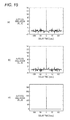
- FIG. 15 shows views illustrating the characteristics of a conventional complementary code.
- (a) is a view showing results of the autocorrelation calculation of the one complementary code sequence a n
- (b) is a view showing results of the autocorrelation calculation of the other complementary code sequence bn
- (c) is a view showing an additional value of the results of the autocorrelation calculations of the two complementary code sequences (a n , b n ).
- the code length L of the complementary codes used in FIG. 15 is 128.
- the result of the autocorrelation calculation of the one complementary code sequence a n of the two complementary code sequences (a n , b n ) is derived in accordance with Exp. (1).
- the result of the autocorrelation calculation of the other complementary code sequence b is derived in accordance with Exp. (2).
- the parameter R represents the result of the autocorrelation calculation.
- the asterisk * represents a complex conjugate operator.
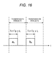
- FIG. 16 is a view illustrating transmission periods T r in a conventional pulse compression radar, and the complementary codes a n , b n which are used in transmission in the transmission periods.
- the transmission interval of transmitting the high-frequency transmission signals which are generated based on the complementary codes respectively is set as the transmission period T r .
- the signal of the reflected wave with respect to the high-frequency transmission signal which is generated based on the complementary code b n is received during the next transmission period T r .
- the signal of the reflected wave undergoes the phase change ⁇ (t) shown in Exp. 4.
- the parameter T p indicates the transmission time per pulse corresponding to a pulse code having the code length L.
- the parameter T c indicates the transmission time in a transmission zone of the high-frequency transmission signal that is generated based on the complementary code a n or b n having the code length L.
- Exp. (5) holds among the parameter T p , the parameter T c , and the parameter L.
- Patent Document 1 is known in connection with the above-discussed problem, i.e., the problem in that, when the high-frequency transmission signals that are generated based on the complementary codes a n , b n , respectively are switchingly transmitted in a time divisional manner, the low range side lobe characteristics is impaired due to the Doppler frequency f d .
- the dispersion/compression type pulse echo system transmitter/receiver shown in Patent Document 1 transmits high-frequency signals which are modulated by code sequences of different pulse compression code sequences in accordance with modes (a B mode and a Doppler mode). Specifically, in the B mode, the transmitter/receiver transmits a high-frequency signal which is modulated by a compression code sequence for a short distance range. In the Doppler mode, the transmitter/receiver transmits a high-frequency transmission signal which is modulated by a Barker code sequence, an M sequence, or the like. According to the configuration, transmission pulses are selectively used in accordance with the measurement target, and a pulse echo caused by a fast moving target which is at a short distance can be reduced.
- the pulse compression is performed while alternately switching over the complementary code sequence used in the B mode, and the M sequence code, Barker code sequence, or the like used in the Doppler mode.
- the impairment of the side lobe level which occurs in the transmission using complementary codes in the case where a target moves is not considered, and depends on characteristics of the side lobe level of the M sequence code, the Barker code sequence, or the like.
- the peak side lobe is about 20 Log(L). Even in the case of the maximum code length of 13 which is known as a Barker code, therefore, the peak side lobe is about 22.3 [dB], and hence affects the measurement performance of a radar device.
- the invention has been conducted in view of the above-discussed conventional circumstances. It is an object of the invention to provide a radar device in which, even when a target moves, the low range side lobe characteristics of a signal of a reflected wave from the target is maintained, and the range side lobe level is effectively suppressed, thereby suppressing impairment of the separation performance in detection of a plurality of targets.
- the invention is directed to the above-described radar device including: a code generator which generates a first code sequence and a second code sequence constituting a pair of complementary codes, a first modulator which modulates the first code sequence to generate a first transmission signal, a second modulator which modulates the second code sequence to generate a second transmission signal, a quadrature modulator which performs quadrature modulation by using the first transmission signal and the second transmission signal that are generated by the first modulator and the second modulator, respectively, an amplifier which generates a high-frequency transmission signal from a signal that is quadrature modulated by the quadrature modulator, and an antenna which transmits the high-frequency transmission signal from a transmission antenna.
- the radar device of the invention even when a target moves, the low range side lobe characteristics of a signal of a reflected wave from the target is maintained, and the range side lobe level is effectively suppressed, whereby impairment of the separation performance in detection of a plurality of targets can be suppressed.
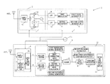
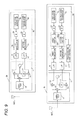
- FIG. 1 is a block diagram showing the internal configuration of a radar device of a first embodiment.
- FIG. 2 shows timing charts related to the operation of the radar device of the first embodiment
- (a) is a view illustrating transmission periods and transmission codes used in the transmission periods T r
- (b) is a view illustrating measurement zones
- (c) is a view illustrating relationships between the transmission periods T r and a discrete time k.
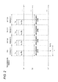
- FIG. 3 is a constellation diagram of a high-frequency transmission signal which is IQ multiplexed in the radar device of the first embodiment.
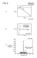
- FIG. 4 shows views showing an IQ correlation value AC(k) on an IQ plane
- (a) is a view showing an IQ correlation value AC(k) before an subtraction process by a subtracter
- (b) is a view showing the IQ correlation value AC(k) which is used in the subtraction process by the subtracter
- (c) is a view showing relationships between the discrete time k and the absolute value
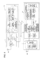
- FIG. 5 is a block diagram showing the internal configuration of a radar device of a second embodiment.
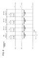
- FIG. 6 shows timing charts related to the operation of the radar device of the second embodiment, (a) is a view illustrating transmission periods T r and transmission codes used in the transmission periods T r , (b) is a view illustrating measurement zones, and (c) is a view illustrating relationships between the transmission periods T r and a discrete time k.
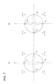
- FIG. 7 shows constellation diagrams of high-frequency transmission signals which are IQ multiplexed in the radar device of the second embodiment
- (a) is a constellation diagram of transmission signals which are IQ multiplexed in M-th and (M+2)-th transmission periods while an complementary code an is allocated to the I axis, and an complementary code b n is allocated to the Q axis
- (b) is a constellation diagram of transmission signals which are IQ multiplexed in (M+1)-th and (M+3)-th transmission periods while the complementary code b n is allocated to the I axis, and the complementary code an is allocated to the Q axis.
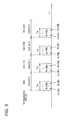
- FIG. 8 is a view showing in detail transmission codes used in the transmission periods T r in the radar device of the second embodiment.
- FIG. 9 shows block diagrams showing the internal configurations of radar transmitters in Modifications 1 of the embodiments, (a) is a diagram showing the internal configuration of a radar transmitter in Modification 1 of the first embodiment, and (b) is a diagram showing the internal configuration of a radar transmitter in Modification 1 of the second embodiment.
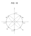
- FIG. 10 is a constellation diagram of a high-frequency transmission signal which is IQ multiplexed while the complementary code an is allocated to the I axis and phase-shifted by ⁇ 45 degrees, and the complementary code b n is allocated to the Q axis and phase-shifted by ⁇ 45 degrees
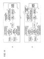
- FIG. 11 shows block diagrams showing the internal configurations of signal processors of radar receivers in Modifications 2 of the embodiments
- (a) is a diagram showing the internal configuration of a signal processor of a radar receiver in Modification 2 of the first embodiment
- (b) is a diagram showing the internal configuration of a signal processor of a radar receiver in Modification 2 of the second embodiment.
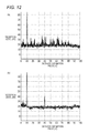
- FIG. 12 shows views showing results of simulations related to the accuracy of detection of a target
- (a) is a view in the case where high-frequency transmission signals which were generated based on complementary codes a n , b n were time-divisionally transmitted by a conventional radar device
- (b) is a view in the case where high-frequency transmission signals which were generated by IQ multiplexing complementary codes a n , b n were transmitted by the radar device of the first embodiment.
- FIG. 13 is a block diagram showing another internal configuration of a transmission signal generator of the radar device of the second embodiment.
- FIG. 14 is a view showing a procedure of producing a code sequence of usual complementary codes.
- FIG. 15 shows views illustrating the characteristics of a conventional complementary code, (a) is a view showing results of an autocorrelation calculation of one complementary code sequence, (b) is a view showing results of an autocorrelation calculation of the other complementary code sequence, and (c) is a view showing an additional value of the results of the autocorrelation calculations of the two complementary code sequences.
- FIG. 16 is a view illustrating transmission periods in a conventional pulse compression radar, and complementary codes which are used in the transmission periods.
- a reception signal which is received by the radar device of the invention contains a signal of a reflected wave which is obtained by reflecting a high-frequency transmission signal transmitted from the radar device, from a target, and noise signals in the periphery of the radar device.
- FIG. 1 is a block diagram showing the internal configuration of the radar device 1 of the first embodiment.
- FIG. 2 shows timing charts related to the operation of the radar device 1 of the first embodiment, (a) of the figure is a view illustrating transmission periods T r and transmission codes used in the transmission periods T r , (b) of the figure is a view illustrating measurement zones, and (c) of the figure is a view illustrating relationships between the transmission periods T r and a discrete time k.
- FIG. 3 is a constellation diagram of a high-frequency transmission signal which is IQ multiplexed in the radar device 1 of the first embodiment.
- FIG. 4 shows views showing an IQ correlation value AC(k) on an IQ plane, (a) of the figure is a view showing an IQ correlation value AC(k) before an subtraction process by a subtracter 31 , (b) of the figure is a view showing the IQ correlation value AC(k) which is used in the subtraction process by the subtracter 31 , and (c) of the figure is a view showing relationships between the discrete time k and the absolute value
- the radar device 1 includes a reference oscillator L 0 , a radar transmitter 2 to which a transmission antenna ANT 0 is connected, and a radar receiver 3 to which a reception antenna ANT 1 is connected.
- the radar device 1 transmits a predetermined intermittent high-frequency transmission signal which is generated by the radar transmitter 2 , from the transmission antenna ANT 0 , and receives the signal of the reflected wave which is reflected from the target, through the radar receiver 3 .
- the radar device 1 performs signal processing on the reception signal which is received through the radar receiver 3 , to detect the presence or absence of a target.
- the target is an object which is to be detected by the radar device 1 , and for example an automobile or a person. This is applicable similarly in the following embodiments.
- the radar transmitter 2 includes a transmission signal generator 4 , and an RF (Radio Frequency) transmitter 11 .
- the transmission signal generator 4 includes a first code generator 5 , a second code generator 6 , a first modulator 7 , a second modulator 8 , an LPF (Low Pass Filter) 9 , and an LPF 10 .
- the transmission signal generator 4 is configured so as to include the LPF 9 and the LPF 10 .
- the LPF 9 and the LPF 10 may be configured in the radar transmitter 2 independently from the transmission signal generator 4 .
- the RF transmitter 11 includes a local oscillator L 1 , a mixer 12 , a first phase shifter 13 , a mixer 14 , an adder 15 , and an amplifier 16 .
- the transmission signal generator 4 Based on a reference signal generated by the reference oscillator L 0 , the transmission signal generator 4 generates a signal which is obtained by multiplying the reference signal a predetermined number of times. The sections of the transmission signal generator 4 operate based on the generated signal.
- the transmission signal generator 4 modulates pulse compression codes of complementary code sequences a n , b n each having a code length of L to periodically generate a base-band transmission signal.
- n 1, . . . , L
- the parameter L indicates the code length of the complementary code sequences a n , b n .
- the transmission signal generated by the transmission signal generator 4 is not a continuous signal.
- T w [s] of M-th to (M+3)-th transmission periods T r for example, an N 0 [number] of samples exist per pulse code with respect of the complementary code sequences a n , b n having a code length of L.
- the first code generator 5 generates a transmission code for pulse compression of the complementary code sequence a n which is a pair of complementary code sequences having the code length of L.
- the first code generator 5 outputs the generated transmission code of the complementary code sequence a n to the first modulator 7 .
- the transmission code of the complementary code sequence a n is referred to as the transmission code an for the sake of convenience.
- the second code generator 6 generates a transmission code for pulse compression of the complementary code sequence b n which is a pair of complementary code sequences having the code length of L.
- the second code generator 6 outputs the generated transmission code of the complementary code sequence b n to the second modulator 8 .
- the transmission code of the complementary code sequence b n is referred to as the transmission code b n for the sake of convenience.
- the first modulator 7 receives the transmission code an output from the first code generator 5 .
- the first modulator 7 performs pulse modulation (amplitude modulation, ASK (Amplitude Shift Keying)) or phase modulation (PSK (Phase Shift Keying)) on the input transmission code an to generate a base-band transmission signal I(k).
- the first modulator 7 outputs a transmission signal I(k) which is equal to or lower than a preset limit band in the generated transmission signal I(k), to the RF transmitter 11 through the LPF 9 .
- the second modulator 8 receives the transmission code b n output from the second code generator 6 .
- the second modulator 8 performs pulse modulation (amplitude modulation, ASK) or phase modulation (PSK) on the input transmission code b n to generate a base-band transmission signal Q(k).
- the second modulator 8 outputs a transmission signal Q(k) which is equal to or lower than a preset limit band in the generated transmission signal Q(k), to the RF transmitter 11 through the LPF 10 .
- the RE transmitter 11 Based on the reference signal generated by the reference oscillator L 0 , the RE transmitter 11 generates a signal which is obtained by multiplying the reference signal a predetermined number of times. The RE transmitter 11 operates based on the generated signal.
- the RE transmitter 11 allocates the transmission signal I(k) output from the first modulator 7 to the I axis of the IQ plane shown in FIG. 3 . Furthermore, the RF transmitter 11 allocates the transmission signal Q(k) output from the second modulator 8 to the Q axis of the IQ plane shown in FIG. 3 . The RE transmitter 11 additionally multiplexes the transmission signal I(k) allocated to the I axis and the transmission signal Q(k) allocated to the Q axis.
- IQ multiplex the process of allocating the transmission signal I(k) output from the first modulator 7 to the I axis, and the transmission signal Q(k) output from the second modulator 8 to the Q axis, and additionally multiplexing the transmission signals I(k) and Q(k) to generate a high-frequency transmission signal.
- the IQ multiplex is performed by the mixer 12 , the first phase shifter 13 , the mixer 14 , and the adder 15 .
- the mixer 12 , the first phase shifter 13 , the mixer 14 , and the adder 15 may be referred to as the quadrature modulator which performs the IQ multiplex.
- the transmission signal I(k) output from the first modulator 7 is multiplied with a signal A cos(2 ⁇ f c t) supplied from the local oscillator L 1 operating at a carrier frequency of f c .
- the parameter A indicates a predetermined amplitude value.
- the transmission signal Q(k) output from the second modulator 8 is multiplied with a signal A sin(2 ⁇ f c t) which is obtained by phase-shifting the signal A cos(2 ⁇ f c t) supplied from the local oscillator L 1 of the carrier frequency of f c by 90 degrees by the first phase shifter 13 .
- the signals which are results of the multiplications in the mixers 12 , 14 are added to each other in the adder 15 .
- a quadrature modulated high-frequency transmission signal s(t) shown in Exp. (6) is generated by IQ multiplex of the complementary codes a n , b n .
- the constellation diagram shown in FIG. 3 is a constellation diagram of a high-frequency transmission signal which is IQ multiplexed while the transmission code an is allocated to the I axis, and the transmission code b n is allocated to the Q axis. Therefore, the high-frequency transmission signal s(t) shown in Exp. (6) is a signal which is generated by IQ multiplexing the transmission code an and the transmission code b n so that one of signal points (A, A), (A, ⁇ A), ( ⁇ A, A), and ( ⁇ A, ⁇ A) shown in FIG. 3 is selected.
- the amplifier 16 receives the high-frequency transmission signal s(t) which is generated in accordance with Exp. (6), amplifies the level of the input high-frequency transmission signal s(t) to a predetermined level, and supplies the amplified signal to the transmission antenna ANT 0 .
- the amplified high-frequency transmission signal s(t) is transmitted so as to be radiated into the space through the transmission antenna ANT 0 .
- the transmission antenna ANT 0 transmits the high-frequency transmission signal s(t) which is output from the RF transmitter 11 , so as to radiate the signal into the space. As shown in FIG. 2( a ), the high-frequency transmission signal s(t) is transmitted during the transmission zone T w in the transmission period T r , but not transmitted during the non-transmission zone (T r ⁇ T w ).
- the radar receiver 3 includes a reception antenna ANT 1 , an RF receiver 17 , and a signal processor 21 .
- the RF receiver 17 includes an amplifier 18 , a frequency converter 19 , and a quadrature detector 20 .
- the signal processor 21 includes A/D converters 22 , 23 , first and second reference signal generators 24 , 25 , first and second correlation value calculators 26 , 27 , an adder 28 , a reception signal extractor 29 , an IQ multiplex interference component extractor 30 , a subtracter 31 , an averaging processor 32 , and an incoming distance estimator 33 .
- the radar receiver 3 periodically calculates the transmission periods T r as signal processing zones in the signal processor 21 .
- the reception antenna ANT 1 receives a signal of a reflected wave which is generated by reflecting the high-frequency transmission signal s(t) transmitted from the radar transmitter 2 , from a target, and noise signals in the periphery of the radar device 1 , as the reception signal.
- the signal of the reflected wave signal is a signal in the high-frequency band.
- the reception signal which is received by the reception antenna ANT 1 is supplied to the RF receiver 17 .
- the radar receiver 3 holds the one reception antenna ANT 1 .
- the reception antenna ANT 1 receives the above-described reception signal in zones corresponding to the transmission periods T r . Therefore, the zones T r where the reception signal is received are set as measurement zones in the radar device 1 .
- the RF receiver 17 Similarly with the RF transmitter 11 based on the reference signal generated by the reference oscillator L 0 , the RF receiver 17 generates a signal which is obtained by multiplying the reference signal the predetermined number of times. The RF receiver 17 operates based on the generated signal. Therefore, the local oscillator L 1 of the RF transmitter 11 can be synchronized with a local oscillator (not shown) of the RF receiver 17 .
- the amplifier 18 receives the high-frequency band signal which is received by the reception antenna ANT 1 , amplifies the level of the input high-frequency band signal, and supplies the amplified signal to the frequency converter 19 .
- the frequency converter 19 receives the high-frequency band signal which is output from the amplifier 18 , down-converts the input high-frequency band signal to the base band, and supplies the down-converted reception signal to the quadrature detector 20 .
- the quadrature detector 20 performs quadrature detection on the base-band reception signal supplied from the frequency converter 19 to generate a base-band reception signal configured by an in-phase signal and a Quadrate signal.
- the quadrature detector 20 outputs the in-phase signal component in the generated reception signal to the A/D converter 22 , and the quadrate signal component in the generated reception signal to the A/D converter 23 .
- the A/D converter 22 performs sampling at the discrete time k on the base-band in-phase signal supplied from the quadrature detector 20 , and converts the in-phase signal which constitutes analog data, to digital data.
- the A/D converter 22 outputs the in-phase signal which is converted to digital data, to the first correlation value calculator 26 .
- the A/D converter 23 performs sampling at the discrete time k on the base-band quadrate signal supplied from the quadrature detector 20 , and converts the quadrate signal which constitutes analog data, to digital data.
- the A/D converter 23 outputs the quadrate signal which is converted to digital data, to the second correlation value calculator 27 .
- the parameter k indicates the discrete time corresponding to the sample number of the base-band transmission signals I(k), Q(k) from which the high-frequency transmission signal that is transmitted in the reception periods T r shown in FIG. 2( a ) originates.
- the reception signal which is converted by the A/D converters 22 , 23 , and which is at the discrete time k is indicated as a complex signal of Exp. (7) by using the in-phase signal I(k) of the reception signal and the quadrate signal Q(k) of the reception signal.
- the range of the discrete time k is similarly applicable also in the following embodiments.
- T r the transmission period of the high-frequency transmission signal s(t) which is generated by IQ multiplex of the transmission code an and the transmission code b n .
- the range of the discrete time k is shown only in the M-th transmission period.
- the first reference signal generator 24 In synchronization with the operation of the transmission signal generator 4 , based on the reference signal generated by the reference oscillator L 0 in a similar manner as in the transmission signal generator 4 , the first reference signal generator 24 generates a signal which is obtained by multiplying the reference signal a predetermined number of times. Based on the generated signal, the first reference signal generator 24 generates a first reference transmission signal I(k) of the same base band as the transmission signal I(k) generated by the first modulator 7 . The first reference signal generator 24 outputs the generated first reference transmission signal I(k) to the first correlation value calculator 26 . In FIG. 1 , the input of the reference signal to the first reference signal generator 24 is not shown.
- the second reference signal generator 25 In synchronization with the operation of the transmission signal generator 4 , based on the reference signal generated by the reference oscillator L 0 in a similar manner as in the transmission signal generator 4 , the second reference signal generator 25 generates a signal which is obtained by multiplying the reference signal the predetermined number of times. Based on the generated signal, the second reference signal generator 25 periodically generates a second reference transmission signal jQ(k) which is obtained by applying Q-axis phase rotation in the IQ multiplex to the transmission signal Q(k) of the same base band as the transmission signal Q(k) generated by the second modulator 8 . The second reference signal generator 25 outputs the generated second reference transmission signal jQ(k) to the second correlation value calculator 27 . In FIG. 1 , the input of the reference signal to the second reference signal generator 25 is not shown.
- the first correlation value calculator 26 receives the complex signal x(k) of the digital data output from the A/D converter 22 , and the first reference transmission signal I(k) output from the first reference signal generator 24 .
- the first correlation value calculator 26 calculates a first correlation value AC 1 (k) of the input complex signal x(k) and the first reference transmission signal I(k).
- the symbol of (asterisk) represents a complex conjugate operator.
- the first correlation value calculator 26 calculates the first correlation value AC 1 (k) in accordance with Exp. (8).
- the first correlation value calculator 26 outputs the first correlation value AC 1 (k) which is calculated in accordance with Exp. (8), to the adder 28 .
- the second correlation value calculator 27 receives the complex signal x(k) of the digital data output from the A/D converter 23 , and the second reference transmission signal jQ(k) output from the second reference signal generator 25 .
- the second correlation value calculator 27 calculates a second correlation value AC 2 (k) of the input complex signal x(k) and the second reference transmission signal jQ(k).
- the symbol of * (asterisk) represents a complex conjugate operator.
- the second correlation value calculator 27 calculates the second correlation value AC 2 (k) in accordance with Exp. (9).
- the second correlation value calculator 27 outputs the second correlation value AC 2 (k) which is calculated in accordance with Exp. (9), to the adder 28 .
- the measurement range (the range of k) may be further limited.
- the radar device 1 can reduce the calculation amounts of the first correlation value calculator 26 and the second correlation value calculator 27 . Namely, the radar device 1 can reduce the power consumption due to the reduction of the calculation amounts by the signal processor 21 .
- the adder 28 receives the first correlation value AC(k) output from the first correlation value calculator 26 , and the second correlation value AC 2 (k) output from the second correlation value calculator 27 .
- the adder 28 adds together the input first correlation value AC 1 (k) and second correlation value AC 2 (k) in a state where the discrete times k are coincident with each other, as shown in Exp. (10) to calculate a third correlation value AC(k).
- the third correlation value calculated by the adder 28 is referred to as “IQ correlation value”.
- the adder 28 outputs the calculated IQ correlation value AC(k) to the reception signal extractor 29 and the subtracter 31 .
- the complementary code fast correlator disclosed in following Reference Non-patent Document 1 may be referenced and applied. This is applicable similarly in the following embodiments.
- the reception signal extractor 29 receives the IQ correlation value AC(k) output from the adder 28 .
- the reception signal extractor 29 extracts an IQ correlation value AC(k pq ) which exceeds a preset predetermined threshold B, from the input IQ correlation value AC(k).
- the reception signal extractor 29 extracts discrete times k pq satisfying Exp. (11), and outputs IQ correlation values AC(k p1 ), AC(k p2 ), . . . , AC(k pv ) in which IQ correlation values AC(k pq ) corresponding to the extracted discrete times k pq are arranged in descending order, to the IQ multiplex interference component extractor 30 .
- the parameter v is a natural number, and indicates the number of discrete times k pq satisfying Exp. (11).
- a predetermined threshold B is a level in which a predetermined margin (about 3 [dB] to 10 [dB]) is added to the noise level.
- a predetermined margin about 3 [dB] to 10 [dB]
- the IQ multiplex interference component extractor 30 receives the IQ correlation values AC(k pq ) output from the reception signal extractor 29 .
- the IQ multiplex interference component extractor 30 calculates an IQ multiplex interference component in accordance with Exp. (12).
- lm ⁇ x ⁇ is an operator for extracting the imaginary component of a complex number x.
- the IQ multiplex interference component extractor 30 outputs the calculated IQ multiplex interference component to the subtracter 31 .
- the subtracter 31 receives the IQ multiplex interference component output from the IQ multiplex interference component extractor 30 . As indicated in Exp. (13), the subtracter 31 removes (subtracts) the IQ multiplex interference component which is calculated based on Exp. (12), from the IQ correlation value AC(k pq ) which is extracted by the reception signal extractor 29 , to derive a fourth correlation value AC(k pq ) from which the IQ multiplex interference component is removed.
- k k pq ⁇ N 0 L+1, k pq , . . . , k pq +N 0 L ⁇ 1.
- the case where k ⁇ 1 or k>(N r +N u ) is not included in the range where the subtracting process is to be performed.
- FIGS. 4( a ) and 4 ( b ) are views in which the IQ correlation value AC(k) is plotted on the complex plane consisting of the I axis and the Q axis.
- FIG. 4( c ) is a view where, in the case where the abscissa indicates the discrete time k, the absolute value
- the radar transmitter 2 transmits the high-frequency transmission signal s(t) which is generated by IQ multiplexing the transmission code an and transmission code b n that are complementary codes.
- the transmission code an and the transmission code b n are not codes having orthogonality to each other, but are code having correlatively.
- an IQ multiplex interference component is generated in the signal of the reflected wave which is generated by reflecting the high-frequency transmission signal s(t) from a target.
- an IQ multiplex interference component appears as a peak range side lobe in a direction perpendicular to the peak direction ⁇ (k pq ) of the IQ correlation value AC(k pq ) satisfying Exp. (11) above in the IQ correlation value AC(k) which is obtained by the adder 28 of the radar receiver 3 .
- the IQ multiplex interference component corresponds to the range side lobe component indicated in the portion enclosed by the broken line.
- the IQ multiplex interference component extractor 30 calculates the component (see Exp. (12)) perpendicular to the peak direction ⁇ (k pq ) of the IQ correlation value AC(k pq ), therefore, the range side lobe component which is indicated in the portion enclosed by the broken line in FIG. 4( b ), and which is in the IQ correlation value AC(k pq ) can be extracted.
- phase rotation ⁇ (k pq ) is applied in order to extract the IQ multiplex interference component.
- a coefficient exp(j ⁇ (k pq )) is multiplied in order to obtain the original phase component.
- lm ⁇ x ⁇ of the second expression of the right-hand side of Exp. (13) is an operator for extracting the imaginary component of the complex number x.
- the subtracter 31 multiples the complex coefficient j indicating application of the phase rotation of 90 degrees in the second expression of the right-hand side of Exp. (13).
- the subtracter 31 can remove the range side lobe component from the IQ correlation values AC(k) extracted by the reception signal extractor 29 , in accordance with Exp. (13).
- the averaging processor 32 receives the fourth correlation value AC′(k) which is derived by the subtracter 31 .
- the averaging processor 32 averages the fourth correlation values AC′(k) which are input in a predetermined plurality of transmission periods T r .
- the averaging processor 32 outputs the average value of the averaged fourth correlation value AC′(k) to the incoming distance estimator 33 .
- the radar device 1 can suppress noise components in the periphery of the radar device 1 , and improve the measurement performance related to estimation of the incoming angle and distance of the target.
- the incoming distance estimator 33 receives the average value which is output from the averaging processor 32 .
- the incoming distance estimator 33 performs a calculation of estimating the distance to the target, based on the input average value.
- the calculation of estimating the distance to the target in the incoming distance estimator 33 is a known technique, and can be realized by referring to, for example, following Reference Non-patent Document 2.
- the incoming distance estimator 33 determines the time difference between the discrete time when the fourth correlation value has the maximum value, and the transmission time of the high-frequency transmission signal. Based on the determined time difference, moreover, the incoming distance estimator 33 estimates the distance to the target.
- the radar device 1 of the first embodiment even when a target moves, the low range side lobe characteristics of a signal of a reflected wave from the target is maintained, and the range side lobe level is effectively suppressed, thereby suppressing impairment of the separation performance in detection of a plurality of targets.
- Patent Document 1 in order to obtain a result of one pulse compression, the three kinds of code sequences, i.e., two kinds of codes constituting a pair of complementary code sequences, and one kind of code sequence such as a Barker code or an M code sequence are used, and therefore a time period corresponding to the three transmission periods must be required.
- the transmission code an and the transmission code b n are IQ multiplexed in transmission, and therefore, in order to obtain a result of one measurement, a time period corresponding to one transmission period in total is required. According to the radar device 1 , therefore, the number of measurements within a predetermined time period can be increased, and namely the measurement performance can be improved.
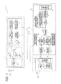
- FIG. 5 is a block diagram showing the internal configuration of the radar device 1 a of the second embodiment.
- FIG. 6 shows timing charts related to the operation of the radar device 1 a of the second embodiment
- (a) of the figure is a view illustrating transmission periods T r and transmission codes used in the transmission periods T r
- (b) of the figure is a view illustrating measurement zones
- (c) of the figure is a view illustrating relationships between the transmission periods T r and a discrete time k.
- FIG. 7 shows constellation diagrams of transmission signals in the radar device 1 a of the second embodiment
- (a) of the figure is a constellation diagram of transmission signals which are IQ multiplexed while an complementary code an is allocated to the I axis, and an complementary code b n is allocated to the Q axis
- (b) of the figure is a constellation diagram of transmission signals which are IQ multiplexed in (M+1)-th and (M+3)-th transmission periods while the complementary code b n is allocated to the I axis, and the complementary code an is allocated to the Q axis.
- FIG. 8 is a view showing in detail transmission codes used in the transmission periods T r in the radar device 1 a of the second embodiment.
- the radar device 1 a alternately switches over the transmission code to be allocated to the I axis in the transmission code to be IQ multiplexed, between the transmission code an and the transmission code b n in each transmission period T r , and the transmission code to be allocated to the Q axis between the transmission code b n and the transmission code an.
- the Doppler frequency f d which is generated in accordance with the movement of the target is calculated, and an IQ multiplex interference component is removed in regard to an IQ correlation value which exceeds the calculated Doppler frequency f d .
- the radar device 1 a includes the reference oscillator L 0 , a radar transmitter 2 a to which the transmission antenna ANT 0 is connected, and a radar receiver 3 a to which the reception antenna ANT 1 is connected.
- the radar device 1 a transmits a predetermined intermittent high-frequency transmission signal which is generated by the radar transmitter 2 a , from the transmission antenna ANT 0 , and receives the signal of the reflected wave which is reflected from the target, through the radar receiver 3 a .
- the radar device 1 performs signal processing on the reception signal which is received through the radar receiver 3 a , to detect the presence or absence of a target.
- the radar transmitter 2 a includes a transmission signal generator 4 a , and the RF transmitter 11 .
- the transmission signal generator 4 a includes a first code generator 5 a , a second code generator 6 a , a first switch SW 1 , a second switch SW 2 , a transmission code controller CT 1 , a first modulator 7 a , a second modulator 8 a , the LPF 9 , and the LPF 10 .
- the transmission signal generator 4 a is configured so as to include the LPF 9 and the LPF 10 .
- the LPF 9 and the LPF 10 may be configured in the radar transmitter 2 a independently from the transmission signal generator 4 a .
- the configuration and operation of the RF transmitter 11 are similar to those of the first embodiment, and therefore the description of the configuration and the operation will be omitted.
- the transmission signal generator 4 a Based on the reference signal generated by the reference oscillator L 0 , the transmission signal generator 4 a generates a signal which is obtained by multiplying the reference signal a predetermined number of times. The sections of the transmission signal generator 4 a operate based on the generated signal.
- the transmission signal generator 4 a modulates pulse compression codes of complementary code sequences a n , b n each having a code length of L to periodically generate a base-band transmission signal.
- n 1, . . . , L
- the parameter L indicates the code length of the complementary code sequences a n , b n .
- the transmission signal generated by the transmission signal generator 4 a is not a continuous signal.
- N 0 number of samples exist as the base-band transmission signal.
- the first code generator 5 a generates a transmission code for pulse compression of the complementary code sequence a n which is a pair of complementary code sequences having the code length of L.
- the first code generator 5 a outputs the generated transmission code an to the first switch SW 1 and the second switch SW 2 .
- the second code generator 6 a generates a transmission code for pulse compression of the complementary code sequence b n which is a pair of complementary code sequences having the code length of L.
- the second code generator 6 a outputs the generated transmission code b n to the first switch SW 1 and the second switch SW 2 .
- the first switch SW 1 receives the transmission code an and transmission code b n which are output from the first code generator 5 a and the second code generator 6 a , respectively. Based on a code switch controlling signal output from the transmission code controller CT 1 , the first switch SW 1 selectively switches over one of the input transmission code an and transmission code bn, and outputs the switched transmission code to the first modulator 7 a.
- the second switch SW 2 receives the transmission code an and transmission code b n which are output from the first code generator 5 a and the second code generator 6 a , respectively. Based on the code switch controlling signal output from the transmission code controller CT 1 , the second switch SW 2 selectively switches over one of the input transmission code an and the transmission code bn, and outputs the switched transmission code to the second modulator 8 a.
- the transmission code controller CT 1 controls the first switch SW 1 and the second switch SW 2 so that the transmission code an and transmission code b n which are input respectively to the first switch SW 1 and the second switch SW 2 are selectively switched over in each transmission period T r .
- the transmission code controller CT 1 outputs the code switch controlling signal instructing that the transmission codes are selectively switched over, to the first switch SW 1 and the second switch SW 2 in each transmission period T r .
- the transmission code controller CT 1 controls the first switch SW 1 so as to output the transmission code an to the first modulator 7 a .
- the transmission code controller CT 1 outputs the code switch controlling signal instructing that the transmission code is switched to the transmission code an, to the first switch SW 1 .
- the transmission code controller CT 1 controls the second switch SW 2 so as to output the transmission code b n to the second modulator 8 a .
- the transmission code controller CT 1 outputs the code switch controlling signal instructing that the transmission code is switched to the transmission code bn, to the second switch SW 2 .
- the transmission code controller CT 1 controls the first switch SW 1 so as to output the transmission code b n to the first modulator 7 a .
- the transmission code controller CT 1 outputs the code switch controlling signal instructing that the transmission code is switched to the transmission code bn, to the first switch SW 1 .
- the transmission code controller CT 1 controls the second switch SW 2 so as to output the transmission code an to the second modulator 8 a .
- the transmission code controller CT 1 outputs the code switch controlling signal instructing that the transmission code is switched to the transmission code an, to the second switch SW 2 .
- the transmission code controller CT 1 controls the first switch SW 1 so as to output the transmission code an to the first modulator 7 a .
- the transmission code controller CT 1 outputs the code switch controlling signal instructing that the transmission code is switched to the transmission code an, to the first switch SW 1 .
- the transmission code controller CT 1 controls the second switch SW 2 so as to output the transmission code b n , to the second modulator 8 a .
- the transmission code controller CT 1 outputs the code switch controlling signal instructing that the transmission code is switched to the transmission code bn, to the second switch SW 2 .
- the transmission code controller CT 1 controls the first switch SW 1 so as to output the transmission code b n to the first modulator 7 a .
- the transmission code controller CT 1 outputs the code switch controlling signal instructing that the transmission code is switched to the transmission code bn, to the first switch SW 1 .
- the transmission code controller CT 1 controls the second switch SW 2 so as to output the transmission code an to the second modulator 8 a .
- the transmission code controller CT 1 outputs the code switch controlling signal instructing that the transmission code is switched to the transmission code an, to the second switch SW 2 .
- the M-th and (M+1)-th or two in total transmission periods shown in FIG. 6( a ) are set as a unit, transmission codes corresponding to the transmission periods in each unit are similarly generated, and repeatedly output to the first modulator 7 a and the second modulator 8 a.
- the first modulator 7 a receives the transmission code an or transmission code b n output from the first switch SW 1 .
- the first modulator 7 a performs pulse modulation (amplitude modulation, ASK) or phase modulation (PSK) on the input transmission code an or transmission code b n to generate a base-band transmission signal I(k).
- the first modulator 7 a outputs a transmission signal I(k) which is equal to or lower than a preset limit band in the generated transmission signal I(k), to the RF transmitter 11 through the LPF 9 .
- the second modulator 8 a receives the transmission code b n or transmission code an output from the second switch SW 2 .
- the second modulator 8 a performs pulse modulation (amplitude modulation, ASK) or phase modulation (PSK) on the input transmission code b n or transmission code an to generate a base-band transmission signal Q(k).
- the second modulator 8 a outputs a transmission signal Q(k) which is equal to or lower than a preset limit band in the generated transmission signal Q(k), to the RF transmitter 11 through the LPF 10 .
- the operations of the RF transmitter 11 and the transmission antenna ANT 0 are substantially similar to those in the first embodiment, and therefore the description of the operation s will be omitted.
- the transmission codes which are supplied to the first modulator 7 a and the second modulator 8 a by the transmission code controller CT 1 are different from each other.
- the constellation diagram of the high-frequency transmission signal which is IQ multiplexed by the RE transmitter 11 is different for each transmission period T r .
- the constellation diagram shown in FIG. 7( a ) is a constellation diagram of a high-frequency transmission signal which is IQ multiplexed in the M-th and (M+2)-th transmission periods T r while the transmission code an is allocated to the I axis, and the transmission code b n is allocated to the Q axis. Therefore, the high-frequency transmission signal s(t) shown in Exp. (6) above is a signal which is generated by IQ multiplexing the transmission codes a n , b n so that one of signal points (A, A), (A, ⁇ A), ( ⁇ A, A), and ( ⁇ A, ⁇ A) shown in FIG. 7( a ) is selected.
- the constellation diagram shown in FIG. 7( b ) is a constellation diagram of a high-frequency transmission signal which is IQ multiplexed in the (M+1)-th and (M+3)-th transmission periods T r while the transmission code b n is allocated to the I axis, and the transmission code an is allocated to the Q axis. Therefore, the high-frequency transmission signal s(t) shown in Exp. (6) above is a signal which is generated by IQ multiplexing the transmission codes a n , b n so that one of signal points (A, A), (A, ⁇ A), ( ⁇ A, A), and ( ⁇ A, ⁇ A) shown in FIG. 7( b ) is selected.
- the radar receiver 3 a includes the reception antenna ANT 1 , the RF receiver 17 , and a signal processor 21 a .
- the RF receiver 17 includes the amplifier 18 , the frequency converter 19 , and the quadrature detector 20 .
- the signal processor 21 a includes the A/D converters 22 , 23 , first and second reference signal generators 24 a , 25 a , first and second correlation value calculators 26 a , 27 a , an adder 28 a , a reception signal selector 29 a , the IQ multiplex interference component extractor 30 , the subtracter 31 , the averaging processor 32 , the incoming distance estimator 33 , and a Doppler frequency estimator 34 .
- the radar receiver 3 a periodically calculates the two-time transmission period T r (2 T r ) as a signal processing zone in the signal processor 21 a.
- reception antenna ANT 1 receives the above-described reception signal in zones corresponding to the transmission periods T r . Therefore, the zones T r where the reception signal is received are set as measurement zones in the radar device 1 a.
- the range of the discrete time k is shown only in the M-th transmission period.
- the first reference signal generator 24 a In synchronization with the operation of the transmission signal generator 4 a , based on the reference signal generated by the reference oscillator L 0 in a similar manner as the transmission signal generator 4 a , the first reference signal generator 24 a generates a timing clock which is obtained by multiplying the reference signal a predetermined number of times. Based on the generated timing clock, the first reference signal generator 24 a generates a first reference transmission signal I(k) of the same base band as the transmission signal I(k) generated by the first modulator 7 a.
- the transmission code controller CT 1 outputs the transmission code an generated by the first code generator 5 a to the first modulator 7 a through the first switch SW 1 .
- the transmission code controller CT 1 outputs the transmission code b n generated by the second code generator 6 a to the first modulator 7 a through the first switch SW 1 .
- the first reference signal generator 24 a In the M-th and (M+2)-th transmission periods T r shown in FIG. 6( a ), therefore, the first reference signal generator 24 a generates the first reference transmission signal I(k) which is identical with the transmission signal I(k) generated based on the transmission code an supplied to the first modulator 7 a.
- the first reference signal generator 24 a In the (M+1)-th and (M+3)-th transmission periods T r shown in FIG. 6( a ), moreover, the first reference signal generator 24 a generates the first reference transmission signal I(k) which is identical with the transmission signal I(k) generated based on the transmission code b n supplied to the first modulator 7 a.
- the first reference signal generator 24 a outputs the first reference transmission signals I(k) generated in the transmission periods T r , to the first correlation value calculator 26 a.
- the second reference signal generator 25 a In synchronization with the operation of the transmission signal generator 4 a , based on the reference signal generated by the reference oscillator L 0 in a similar manner as the transmission signal generator 4 a , the second reference signal generator 25 a generates a timing clock which is obtained by multiplying the reference signal a predetermined number of times. Based on the generated timing clock, the second reference signal generator 25 a periodically generates the second reference transmission signal jQ(k) which is obtained by applying Q-axis phase rotation in the IQ multiplex to the transmission signal Q(k) of the same base band as the transmission signal Q(k) generated by the second modulator 8 a.
- the transmission code controller CT 1 outputs the transmission code b n generated by the second code generator 6 a to the second modulator 8 a through the second switch SW 2 .
- the transmission code controller CT 1 outputs the transmission code an generated by the first code generator 5 a to the second modulator 8 a through the first switch SW 1 .
- the second reference signal generator 25 a In the M-th and (M+2)-th transmission periods T r shown in FIG. 6( a ), therefore, the second reference signal generator 25 a generates the second reference transmission signal jQ(k) which is obtained by applying O-axis phase rotation in the IQ multiplex to the transmission signal Q(k) that is identical with the transmission signal Q(k) generated based on the transmission code b, supplied to the second modulator 8 a.
- the second reference signal generator 25 a In the (M+1)-th and (M+3)-th transmission periods T r shown in FIG. 6( a ), moreover, the second reference signal generator 25 a generates the second reference transmission signal jQ(k) which is obtained by applying O-axis phase rotation in the IQ multiplex to the transmission signal Q(k) that is identical with the transmission signal Q(k) generated based on the transmission code an supplied to the second modulator 8 a.
- the second reference signal generator 25 a outputs the second reference transmission signals jQ(k) generated in the transmission periods T r , to the second correlation value calculator 27 a.
- the first correlation value calculator 26 a receives the complex signal x(k) of the digital data output from the A/D converter 22 , and the first reference transmission signal I(k) output from the first reference signal generator 24 a .
- the first correlation value calculator 26 a calculates a first correlation value AC 1 (k) of the input complex signal x(k) and the first reference transmission signal I(k).
- the symbol of * (asterisk) represents a complex conjugate operator.
- the first correlation value calculator 26 a calculates the first correlation value AC 1 (k) in accordance with Exp. (8) above.
- the first correlation value calculator 26 a outputs the first correlation value AC 1 (k) which is calculated in accordance with Exp. (8), to the adder 28 a.
- the second correlation value calculator 27 a receives the complex signal x(k) of the digital data output from the A/D converter 23 , and the second reference transmission signal jQ(k) output from the second reference signal generator 25 a .
- the second correlation value calculator 27 a calculates a second correlation value AC 2 (k) of the input complex signal x(k) and the second reference transmission signal jQ(k).
- the symbol of * (asterisk) represents a complex conjugate operator.
- the second correlation value calculator 27 a calculates the second correlation value AC 2 (k) in accordance with Exp. (9) above.
- the second correlation value calculator 27 a outputs the second correlation value AC 2 (k) which is calculated in accordance with Exp. (9), to the adder 28 a.
- the measurement range (the range of k) may be further limited.
- the radar device 1 a can reduce the calculation amounts of the first correlation value calculator 26 a and the second correlation value calculator 27 a . Namely, the radar device 1 a can reduce the power consumption due to the reduction of the calculation amounts by the signal processor 21 a.
- the adder 28 a receives the first correlation value AC 1 (k) output from the first correlation value calculator 26 a , and the second correlation value AC 2 (k) output from the second correlation value calculator 27 a .
- the adder 28 a adds together the input first correlation value AC 1 (k) and second correlation value AC 2 (k) in a state where the discrete times k are coincident with each other, as shown in Exp. (10) above to calculate the IQ correlation value AC(k).
- the adder 28 a outputs the calculated IQ correlation value AC(k) to the reception signal selector 29 a and the subtracter 31 .
- the adder 28 a outputs first-half correlation values AC sub1 (k) of the IQ correlation value AC(k) in the first-half portions of the transmission zones T w in the transmission periods T r , to the Doppler frequency estimator 34 . Furthermore, the adder 28 a outputs second-half correlation values AC sub2 (k+(N r /2)) of the IQ correlation value ACM in the second-half portions of the transmission zones T w in the transmission periods T r , to the Doppler frequency estimator 34 .
- the Doppler frequency estimator 34 receives the first-half correlation values AC sub1 (k) and second-half correlation values AC sub2 (k+(N r /2)) output from the adder 28 a .
- the Doppler frequency estimator 34 calculates the Doppler frequency f d in the IQ correlation value AC(k) based on the input first-half correlation values AC sub1 (k) and second-half correlation values AC sub2 (k+(N r /2).
- FIG. 8 is a view showing in detail the transmission codes used in the transmission periods T r in the radar device 1 a of the second embodiment.
- the complementary code sequences a n , b n are obtained by coupling c n , d n which are a pair of subcomplementary codes having a code length L/2, as indicated by Exp. (14).
- c n , d n which are a pair of subcomplementary codes can be expressed as Exp. (15)
- the second-half correlation values AC sub2 (k+(N r /2)) in the second-half portions of the transmission zones T w are phase-shifted by ⁇ 90 degrees with respect to the first-half correlation values AC sub1 (k) in the first-half portions of the transmission zones T w . Therefore, the Doppler frequency estimator 34 rotates the phase of the second-half correlation value AC sub2 (k+(N r /2)) by 90 degrees in order to align the phase with that of the first-half correlation value AC sub1 (k).
- the Doppler frequency estimator 34 multiplies the second-half correlation value AC sub2 (k+(N r /2)) with the imaginary coefficient j.
- the second-half correlation values AC sub2 (k+N r /2)) in the second-half portions of the transmission zones T w are phase-shifted by 90 degrees with respect to the first-half correlation values AC sub1 (k) in the first-half portions of the transmission zones T w . Therefore, the Doppler frequency estimator 34 rotates the phase of the second-half correlation value AC sub2 (k+(N r /2)) by ⁇ 90 degrees in order to align the phase with that of the first-half correlation value AC sub1 (k).
- the Doppler frequency estimator 34 multiplies the second-half correlation value AC sub2 (k+(N r /2)) with the imaginary coefficient ⁇ j.
- the reception signal selector 29 a receives the IQ correlation value AC(k) output from the adder 28 a , and the Doppler frequency f d (k) output from the Doppler frequency estimator 34 .
- the reception signal selector 29 a selects an IQ correlation value AC(k) which exceeds the preset predetermined threshold B, and in which the Doppler frequency f d (k) is not lower than a preset predetermined threshold D, from the input IQ correlation value AC(k).
- the reception signal selector 29 a extracts discrete times k pq satisfying Exp. (22), and outputs IQ correlation values (k p1 ), AC(k p2 ), AC(k pv ) in which IQ correlation values AC(k pq ) corresponding to the extracted discrete times k are arranged in descending order, to the IQ multiplex interference component extractor 30 .
- the parameter v is a natural number, and indicates the number of discrete times k pq satisfying Exp. (11).
- the predetermined threshold D indicates a value at which, in the signal processing, the signal processor 21 a cannot neglect the influence of the Doppler frequency f d that is generated in accordance with the movement.
- the meaning of the predetermined threshold D is applicable similarly in the following embodiments.
- the averaging processor 32 receives the fourth correlation value AC′(k) which is derived by the subtracter 31 .
- the addition is performed for each of results of correlation calculations at the times k.
- the averaging processor 32 outputs the average value of the averaged fourth correlation value AC′(k) to the incoming distance estimator 33 .
- the side lobe can be made ideally zero by using the property of complementary codes.
- a process may be added in which noise components are suppressed by further performing an averaging process for a plurality of radar transmission times, while setting results of the addition processes of correlation calculation values for 2T r which are these two radar transmission periods (T r ), as one unit. This enables the radar device 1 to suppress noise components in the periphery of the radar device 1 , and improve the measurement performance related to estimation of the incoming angle and distance of the target.
- the operations of the IQ multiplex interference component extractor 30 , the subtracter 31 , and the incoming distance estimator 33 are similar to those in the first embodiment, and therefore the description of the operations will be omitted.
- the radar device 1 a of the second embodiment even when a target moves, the low range side lobe characteristics of a signal of a reflected wave from the target is maintained, and the range side lobe level is effectively suppressed, whereby impairment of the separation performance in detection of a plurality of targets can be suppressed.
- the transmission code an and the transmission code b n are IQ multiplexed in transmission, and therefore, in order to obtain a result of one measurement, a time period corresponding to two transmission periods in total is required. According to the radar device 1 a , similarly with the radar device 1 of the first embodiment, therefore, the number of measurements within a predetermined time period can be increased, and namely the measurement performance can be improved.
- the radar device 1 a selects an IQ correlation value which exceeds the predetermined threshold B, and in which the Doppler frequency f d exceeds the preset predetermined threshold D, and removes an IQ multiplex interference component in the selected IQ correlation value. Therefore, the radar device 1 a does not perform the removal of an IQ multiplex interference component on a signal of a reflected wave in which, even when affected by the Doppler frequency f d that is generated in accordance with the movement of the target, the low range side lobe characteristics are not impaired.
- the radar device 1 a performs the removal of an IQ multiplex interference component, only on a signal of a reflected wave in which, when affected by the Doppler frequency f d that is generated in accordance with the movement of the target, the low range side lobe characteristics are impaired.
- the amount of calculation for removing an IQ multiplex interference component can be remarkably reduced as compared to the radar device 1 of the first embodiment.
- FIG. 9 shows block diagrams showing the internal configurations of radar transmitters in Modifications 1 of the embodiments
- (a) of the figure is a diagram showing the internal configuration of a radar transmitter 2 b in Modification 1 of the first embodiment
- (b) of the figure is a diagram showing the internal configuration of a radar transmitter 2 c in Modification 1 of the second embodiment.
- FIG. 10 is a constellation diagram of a high-frequency transmission signal which is IQ multiplexed while the complementary code an is allocated to the I axis and phase-shifted by ⁇ 45 degrees, and the complementary code b n is allocated to the Q axis and phase-shifted by ⁇ 45 degrees
- the reference oscillator L 0 shown in FIG. 1 is not shown, but, based on the reference signal generated by the reference oscillator L 0 , the transmission signal generator 4 b generates a signal which is obtained by multiplying the reference signal a predetermined number of times.
- the sections of the transmission signal generator 4 b operate based on the generated signal.
- the RE transmitter 11 Based on the reference signal generated by the reference oscillator L 0 , also the RE transmitter 11 generates a signal which is obtained by multiplying the reference signal the predetermined number of times. The RE transmitter 11 operates based on the generated signal.
- description will be made in the sequence of the radar transmitter 2 b in Modification 1 of the first embodiment, and the radar transmitter 2 c in Modification 1 of the second embodiment.
- the radar transmitter 2 b in Modification 1 of the first embodiment includes a transmission signal generator 4 b , and the RF transmitter 11 .
- the transmission signal generator 4 b includes a first code generator 5 b , a second code generator 6 b , a second phase shifter 35 , a third phase shifter 36 , a first modulator 7 b , a second modulator 8 b the LPF 9 , and the LPF 10 .
- the transmission signal generator 4 b is configured so as to include the LPF 9 and the LPF 10 .
- the LPF 9 and the LPF 10 may be configured in the radar transmitter 2 b independently from the transmission signal generator 4 b .
- the configuration and operation of the RF transmitter 11 are similar to those of the first embodiment, and therefore the description of the configuration and the operation will be omitted.
- the configuration and operation of the radar receiver in Modification 1 of the first embodiment are similar to those of the radar receiver 3 in the first embodiment, and therefore the description of the configuration and the operation will be omitted.
- the transmission code an generated by the first code generator 5 b is supplied to the second phase shifter 35 .
- the transmission code b n generated by the second code generator 6 b is supplied to the third phase shifter 36 .
- the second phase shifter 35 applies phase rotation corresponding to the predetermined angle ⁇ to the input transmission code an. As described above, for example, the second phase shifter 35 applies phase rotation of ⁇ 45 degrees to the transmission code an output from the first code generator 5 b . The second phase shifter 35 supplies the phase-rotated transmission code an to the first modulator 7 b.
- the third phase shifter 36 applies phase rotation corresponding to the predetermined angle ⁇ to the input transmission code bn. As described above, for example, the third phase shifter 36 applies phase rotation of ⁇ 45 degrees to the transmission code b n output from the second code generator 6 b . The third phase shifter 36 supplies the phase-rotated transmission code b n to the second modulator 8 b.
- the radar transmitter 2 c in Modification 1 of the second embodiment includes a transmission signal generator 4 c , and the RF transmitter 11 .
- the transmission signal generator 4 c includes a first code generator 5 c , a second code generator 6 c , a second phase shifter 37 , a third phase shifter 38 , the first switch SW 1 , the second switch SW 2 , a transmission code controller CT 2 , a first modulator 7 c , a second modulator 8 c , the LPF 9 , and the LPF 10 .
- the transmission signal generator 4 b is configured so as to include the LPF 9 and the LPF 10 .
- the LPF 9 and the LPF 10 may be configured in the radar transmitter 2 c independently from the transmission signal generator 4 c .
- the configuration and operation of the RF transmitter 11 are similar to those of the second embodiment, and therefore the description of the configuration and the operation will be omitted.
- the configuration and operation of the radar receiver in Modification 1 of the second embodiment are similar to those of the radar receiver 3 a in the second embodiment, and therefore the description of the configuration and the operation will be omitted.
- the transmission code an generated by the first code generator 5 c is supplied to the second phase shifter 37 .
- the transmission code b n generated by the second code generator 6 c is supplied to the third phase shifter 38 .
- the second phase shifter 37 applies phase rotation corresponding to the predetermined angle ⁇ to the input transmission code an. As described above, for example, the second phase shifter 37 applies phase rotation of ⁇ 45 degrees to the transmission code an output from the first code generator 5 c . The second phase shifter 37 supplies the phase-rotated transmission code an to the first switch SW 1 and the second switch SW 2 .
- the third phase shifter 38 applies phase rotation corresponding to the predetermined angle ⁇ to the input transmission code bn. As described above, for example, the third phase shifter 38 applies phase rotation of ⁇ 45 degrees to the transmission code b n output from the second code generator 6 c . The third phase shifter 38 supplies the phase-rotated transmission code b n to the first switch SW 1 and the second switch SW 2 .
- the operations of the first switch SW 1 , the second switch SW 2 , the transmission code controller CT 2 , the first modulator 7 c , and the second modulator 8 c are similar to those in the second embodiment, and therefore the description of the operations will be omitted.
- the radar devices of Modifications 1 of the embodiments generate the high-frequency transmission signal based on the signal point arrangement after IQ multiplex shown in FIG. 10 .
- an average transmission power can be reduced because, in the case where phase rotation of 45 degrees or ⁇ 45 degrees is applied in the phase shifter, the signal points of the above-described high-frequency transmission signal s(t) in IQ multiplex are placed on the I axis and the Q axis.
- FIG. 11 shows block diagrams showing the internal configurations of signal processors of radar receivers in Modifications 2 of the embodiments
- (a) of the figure is a diagram showing the internal configuration of a signal processor 21 d of a radar receiver in Modification 2 of the first embodiment
- (b) of the figure is a diagram showing an internal configuration of a signal processor 21 e of the radar receiver in Modification 2 of the second embodiment.
- the IQ multiplex interference component extractor 30 calculates the component perpendicular to the phase component ⁇ (k pq ), as an IQ multiplex interference component.
- an IQ multiplex interference component generator 39 is disposed in place of the IQ multiplex interference component extractor 30 .
- an IQ multiplex interference component generator 40 is disposed in place of the IQ multiplex interference component extractor 30 .
- the IQ multiplex interference component generators 39 , 40 accurately calculate a replica of the IQ multiplex interference component based on the phase component ⁇ (k pq ).
- the signal processor 21 d in Modification 2 of the first embodiment includes the A/D converters 22 , 23 , the first and second reference transmission signal generators 24 , 25 , the first and second correlation value calculators 26 , 27 , the adder 28 , the reception signal extractor 29 , the IQ multiplex interference component replica generator 39 , the subtracter 31 , the averaging processor 32 , and the incoming distance estimator 33 .
- the signal processor 21 d periodically calculates the transmission periods T r as signal processing zones in the signal processor 21 .
- the configurations and operations of the radar transmitter and the RF receiver of the radar receiver in Modification 2 of the first embodiment are similar to those of the radar transmitter 2 and the RE receiver 17 in the first embodiment, and therefore the description of the configurations and the operations will be omitted.
- the operations of the A/D converters 22 , 23 , the first and second reference transmission signal generators 24 , 25 , the first and second correlation value calculators 26 , 27 , the adder 28 , the reception signal extractor 29 , the averaging processor 32 , and the incoming distance estimator 33 are similar to those of the first embodiment, and therefore the description of the operations will be omitted.
- the IQ multiplex interference component replica generator 39 receives the IQ correlation values AC(k pq ) output from the reception signal extractor 29 . Based on the IQ correlation values AC(k pq ), the IQ multiplex interference component replica generator 39 calculates an IQ multiplex interference component replica U(k) in accordance with Exp. (23). The IQ multiplex interference component replica generator 39 outputs the calculated IQ multiplex interference component replica U(k) to the subtracter 31 .
- k k pq N 0 L+1, k pq , . . . , k pq +N 0 L ⁇ 1.
- the case where k ⁇ 1 or k>(N r +N u ) is not included in the range where the replica producing process is to be performed.
- the subtracter 31 receives the IQ multiplex interference component replica U(k) output from the IQ multiplex interference component replica generator 39 . As indicated in Exp. (24), the subtracter 31 removes (subtracts) the IQ multiplex interference component replica U(k) which is calculated based on Exp. (23), from the IQ correlation values AC(k) which are extracted by the reception signal extractor 29 . The subtracter 31 derives the fourth correlation value AC′(k) from which the IQ multiplex interference component is accurately removed, as a result of the removal. The subtracter 31 outputs the derived fourth correlation value AC(k) to the averaging processor 32 .
- the subtracter 31 can accurately remove the range side lobe component from the IQ correlation values AC(k) which are extracted by the reception signal extractor 29 . Also when a signal of a reflected wave reflected from a moving target is received, therefore, the subtracter 31 can obtain the fourth correlation value AC′(k) in which the range side lobe level is effectively suppressed.
- the signal processor 21 e of the radar receiver in Modification 2 of the second embodiment includes the A/D converters 22 , 23 , the first and second reference transmission signal generators 24 a , 25 a , the first and second correlation value calculators 26 a , 27 a , the adder 28 a , the reception signal selector 29 a , the IQ multiplex interference component replica generator 40 , the subtracter 31 , the averaging processor 32 , the incoming distance estimator 33 , and the Doppler frequency estimator 34 .
- the signal processor 21 e periodically calculates the two-time transmission period T r (2T r ) as a signal processing zone in the signal processor 21 e .
- the configurations and operations of the radar transmitter and the RF receiver of the radar receiver in Modification 2 of the second embodiment are similar to those of the radar transmitter 2 a and the RF receiver 17 in the second embodiment, and therefore the description of the configurations and the operations will be omitted.
- the operations of the A/D converters 22 , 23 , the first and second reference transmission signal generators 24 a , 25 a , the first and second correlation value calculators 26 a , 27 a , the adder 28 a , the reception signal selector 29 a , the Doppler frequency estimator 34 , the averaging processor 32 , and the incoming distance estimator 33 are similar to those of the second embodiment, and therefore the description of the operations will be omitted.
- the IQ multiplex interference component replica generator 40 receives the IQ correlation values AC(k pq ) output from the reception signal extractor 29 a . Based on the phase component ⁇ (k pq ) of the calculated IQ correlation values AC(k pq ), the IQ multiplex interference component replica generator 40 calculates the IQ multiplex interference component replica U(k) in accordance with above-described Exp. (22). The IQ multiplex interference component replica generator 40 outputs the calculated IQ multiplex interference component replica U(k) to the subtracter 31 .
- k k pq ⁇ N 0 L+1, k pq , . . . , k pq +N 0 L ⁇ 1.
- the case where k ⁇ 1 or k>(N r +N u ) is not included in the range where the replica producing process is to be performed.
- the subtracter 31 receives the IQ multiplex interference component replica U(k) output from the IQ multiplex interference component replica generator 40 . As indicated in above-described Exp. (23), the subtracter 31 removes (subtracts) the IQ multiplex interference component replica U(k) which is calculated by above-described Exp. (23), from the IQ correlation values AC(k) which are extracted by the reception signal extractor 29 . The subtracter 31 derives the fourth correlation value AC′(k) from which the IQ multiplex interference component is accurately removed, as a result of the removal. The subtracter 31 outputs the derived fourth correlation value AC′(k) to the averaging processor 32 .
- the subtracter 31 can accurately remove the range side lobe component from the IQ correlation values AC(k pq ) which are selected by the reception signal selector 29 a . Also when a signal of a reflected wave reflected from a moving target is received, the subtracter 31 can obtain the fourth correlation value AC′(k pq ) in which the range side lobe level is effectively suppressed.
- the radar devices of Modifications 2 of the embodiments accurately generate the IQ multiplex interference component. According to the radar devices of Modifications 2 of the embodiments, in addition to the effects of the above-described radar device 1 or 1 a , therefore, impairment of the low range side lobe characteristics due to movement of the target can be more effectively suppressed.
- FIG. 12 shows views showing results of simulations related to the accuracy of detection of a target
- (a) of the figure is a view in the case where high-frequency transmission signals which were generated based on the complementary codes a n , b n were time-divisionally transmitted by a conventional radar device
- (b) of the figure is a view in the case where high-frequency transmission signals which were generated by IQ multiplexing the complementary codes a n , b n were transmitted by the radar device of the first embodiment.
- the signal (main lobe) of a reflected wave reflected from a target which exists in a position separated from a conventional radar device by 40 [m] is buried in the signal (range side lobe) of a reflected wave reflected from another target which is located at a short distance (10 [m]).
- high-frequency transmission signals which are generated respectively based on the complementary codes a n , b n are transmitted in a time divisional manner by a conventional radar device, as described above, it is difficult to detect the target which is originally located in the position of 40 [m].
- FIG. 12( b ) shows a state where a target which exists in a position separated from the radar device 1 by 10 [m], and that which exists in a position separated by 40 [m] were accurately detected.
- the radar device 1 of the first embodiment even in the case where the target which exists in a position separated by 10 [m] moves and the influence of the Doppler frequency f d is exerted, therefore, the low range side lobe characteristics of the signal of a reflected wave reflected from the target can be maintained.
- the radar device 1 of the first embodiment namely, the target which exists in a position separated by 10 [m], and that which exists in a position separated by 14 [m] can be accurately detected.
- the A/D converters 22 , 23 convert the in-phase signal and Quadrate signal output from the quadrature detector 20 of the RF receiver 17 , to digital data by oversampling corresponding to the discrete time k.
- the A/D converters 22 , 23 may not perform A/D conversion at the same sampling rate as the base-band transmission signal in the radar transmitter 2 .
- the base-band transmission signal is generated by using the sample number of N r for the code length of L. This corresponds to oversampling of N r /L samples per code.
- the signal process on the reception signal is enabled.
- the first code generator 5 a , second code generator 6 a , first switch SW 1 , and second switch SW 2 which are described above may not be disposed in the transmission signal generator 4 a , and, as shown in FIG. 13 , a transmission code storage CM which previously stores the transmission code an and transmission code b n generated by the transmission signal generator 4 a may be disposed.
- the transmission code storage CM shown in FIG. 13 is not limited to the second embodiment, but is similarly applicable to the first embodiment.
- FIG. 13 is a block diagram showing the internal configuration of a transmission signal generator 4 f which is another example of the transmission signal generator 4 a of the radar device 1 a of the second embodiment.
- the transmission signal generator 4 f includes the transmission code storage CM, a transmission code controller CT 3 , a first modulator 7 f , a second modulator 8 f , the LPF 9 , and the LPF 10 .
- the transmission code controller CT 3 cyclically reads out the transmission code to be output to the first modulator 7 f and the second modulator 8 f , from the transmission code storage 7 a , and outputs it. Specifically, in the M-th and (M+2)-th transmission periods T r shown in FIG. 6( a ), the transmission code controller CT 3 reads out the transmission code an from the transmission code storage CM, and outputs it to the first modulator 7 f , and further reads out the transmission code b n and outputs it to the second modulator 8 f.
- the transmission code controller CT 3 reads out the transmission code b n from the transmission code storage CM, and outputs it to the first modulator 7 f , and further reads out the transmission code an and outputs it to the second modulator 8 f .
- the operations subsequent to the respective outputs to the first modulator 7 f and the second modulator 8 f are similar to those of the above-described embodiments, and therefore description of the similar contents will be omitted.
- the radar device of the invention is useful as a radar device in which, even when a target moves, the low range side lobe characteristics of a signal of a reflected wave from the target is maintained, and the range side lobe level is effectively suppressed, thereby suppressing impairment of the separation performance in detection of a plurality of targets.
Landscapes
- Engineering & Computer Science (AREA)
- Radar, Positioning & Navigation (AREA)
- Remote Sensing (AREA)
- Computer Networks & Wireless Communication (AREA)
- Physics & Mathematics (AREA)
- General Physics & Mathematics (AREA)
- Radar Systems Or Details Thereof (AREA)
Abstract
Description
- The present invention relates to a radar device which receives a signal of a reflected wave that is reflected from a target, through an antenna to detect the target.
- A radar device radiates a radio wave from a measuring point, which receives a signal of a reflected wave that is reflected from a target, and which measures the distance between the measuring point and the target, the direction, and the like. Recently, particularly, a radar device which can detect not only an automobile, but also a pedestrian as a target by a high-resolution measurement using a short-wavelength radio wave such as a microwave or a millimeter wave has been developed.
- A radar device sometimes receives a signal in which a reflected wave from a target at a short distance and that from a target at a long distance are mixed with each other. In the case where a range side lobe appears in the autocorrelation characteristics of a signal of a reflected wave from a target at a short distance, particularly, the range side lobe is sometimes mixed with a main lobe appearing in the autocorrelation characteristics of a signal of a reflected wave from a target at a long distance. In this case, the accuracy of detection in which the radar device detects the target at a long distance may be impaired.
- In the case where an automobile and a pedestrian are at the same distance from a measuring point, moreover, a radar device sometimes receives a signal in which signals of reflected wave from the automobile and pedestrian having different radar cross sections (RCS) are mixed with each other. It is usually said that the radar cross section of a pedestrian is smaller than that of an automobile. Therefore, a radar device is requested to, even in the case where an automobile and a pedestrian are at the same distance from a measuring point, properly receive not only a reflected wave from the automobile, but also that from the pedestrian.
- Therefore, a radar device which must perform a high-resolution measurement on a plurality of targets such as those described above is requested to transmit a pulse wave or pulse modulated wave having characteristics in which the autocorrelation characteristics are in the low range side lobe level (hereinafter, referred to as “low range side lobe characteristics”). Moreover, such a radar device is requested to have a reception dynamic range which is so wide that, in the reception by the radar device, signals of reflected waves reflected from targets that cause various reception levels depending on the distance and kind of a target can be received.
- In regard to the above-described low range side lobe characteristics, a pulse compression radar has been known which, by using a complementary code, transmits a high-frequency transmission signal as a pulse wave or pulse modulated wave having the low range side lobe characteristics. Here, the pulse compression means that a pulse signal is pulse-modulated or phase-modulated, transmission is performed by using a signal having a wide pulse width, and, in signal processing after reception, the received signal is demodulated and converted (compressed) to a signal having a narrow pulse width, and is a method of equivalently enhancing the reception power. According to the pulse compression, the target detectable distance can be increased, and the distance estimation accuracy with respect to the detectable distance can be improved.
- A complementary code is configured by a plurality of, for example, two complementary code sequences (an, bn), and has characteristics that, considering results of autocorrelation calculations of one complementary code sequence an and the other complementary code sequence bn, in the case where the results of autocorrelation calculations are added together while the delay times (shift times) τ [sec.] are made consistent with each other, the range side lobe is zero. The parameter n is n=1, 2, . . . , L. The parameter L indicates the code sequence length, or simply the code length.
- A method of producing a complementary code will be described with reference to
FIG. 14 .FIG. 14 is a view showing an example of a procedure of producing a code sequence of usual complementary codes. As shown inFIG. 14 , from the descriptions of the fourth and fifth rows, a subcode sequence (c, d) consisting of an element of 1 or an element of −1 and having a code length of L=2p-1 is generated, and, from the descriptions of the sixth and seventh rows, a complementary code sequence (a, b) having a code length of L=2p is generated. Here, one complementary code sequence a is a coupling of the subcode sequence c and the subcode sequence d, and the other complementary code sequence b is a coupling of the subcode sequence c and the subcode sequence −d. - The code sequences a, b indicate complementary code sequences, respectively, and the code sequences c, d indicate subcode sequences constituting a complementary code sequence, respectively. The parameter p defines the code length L of the generated complementary code sequences (a, b).
- The characteristics of such a complementary code (complementary code sequence) will be described with reference to
FIG. 15 .FIG. 15 shows views illustrating the characteristics of a conventional complementary code. In the figure, (a) is a view showing results of the autocorrelation calculation of the one complementary code sequence an, (b) is a view showing results of the autocorrelation calculation of the other complementary code sequence bn, and (c) is a view showing an additional value of the results of the autocorrelation calculations of the two complementary code sequences (an, bn). The code length L of the complementary codes used inFIG. 15 is 128. - The result of the autocorrelation calculation of the one complementary code sequence an of the two complementary code sequences (an, bn) is derived in accordance with Exp. (1). The result of the autocorrelation calculation of the other complementary code sequence b is derived in accordance with Exp. (2). The parameter R represents the result of the autocorrelation calculation. In the case where n>L or n<1, the complementary code sequences an, bn are set to zero (i.e., when n>L or n<1, an=0, bn=0). The asterisk * represents a complex conjugate operator.
-
- As shown in
FIG. 15( a), in the result Raa(τ) of the autocorrelation calculation of the one complementary code sequence an derived in accordance with Exp. (1), a peak exists when the delay time τ is zero, and a range side lobe exists when the delay time τ is not zero. Similarly, as shown inFIG. 15( b), in the result Rbb(τ) of the autocorrelation calculation of the other complementary code sequence bn derived in accordance with Exp. (2), a peak exists when the delay time τ is zero, and a range side lobe exists when the delay time τ is not zero. - As shown in
FIG. 15( b), in the additional value of the results (Raa(τ), Rbb(τ)) of the autocorrelation calculations, a peak exists when the delay time (or the shift time) τ is zero (hereinafter, the peak when the delay time τ is zero is referred to as the main lobe), and a range side lobe does not exist and is zero when the delay time τ is not zero. This is expressed by Exp. (3). InFIGS. 15( a) to (c), the abscissa indicates the delay time (τ) in the autocorrelation calculation, and the ordinate indicates the calculated result of the autocorrelation calculation. -
[Exp. 3] -
R aa(τ)+R bb(τ)≠0, when τ=0 -
R aa(τ)+R bb(τ)=0, when τ≠0 (3) - Consequently, furthermore, a pulse compression radar has been known which, as shown in
FIG. 16 , transmits in a time divisional manner a high-frequency transmission signal that is generated based on the above-described complementary code an, and a high-frequency transmission signal that is generated based on the complementary code bn, while switching over the signals in each predetermined transmission period.FIG. 16 is a view illustrating transmission periods Tr in a conventional pulse compression radar, and the complementary codes an, bn which are used in transmission in the transmission periods. When a target moves in the case of reception in such a conventional pulse compression radar, the received reception signal is affected by a phase change θ(t) shown in Exp. (4) due to a Doppler frequency fd that is generated in accordance with the movement. The parameter t represents the time. -
[Exp. 4] -
θ(t)=2π×f d ×t (4) - In a state where an influence of such a phase change θ(t) is exerted, there arises a problem in that the range side lobe level in the autocorrelation characteristics of the reception signal is not zero, and the low range side lobe characteristics in the autocorrelation characteristics of the reception signal are not realized.
- This problem will be specifically described with reference to
FIG. 16 . InFIG. 16 , the transmission interval of transmitting the high-frequency transmission signals which are generated based on the complementary codes respectively is set as the transmission period Tr. In this case, after the transmission of the high-frequency transmission signal which is generated based on the complementary code an, the signal of the reflected wave with respect to the high-frequency transmission signal which is generated based on the complementary code bn is received during the next transmission period Tr. However, the signal of the reflected wave undergoes the phase change θ(t) shown in Exp. 4. - Depending on the magnitude of the product of the transmission period Tr and the Doppler frequency fd contained in the reflected wave signal, therefore, the above-described ideal low range side lobe characteristics are hardly obtained, and the low range side lobe characteristics are impaired. In
FIG. 16 , the parameter Tp indicates the transmission time per pulse corresponding to a pulse code having the code length L. The parameter Tc indicates the transmission time in a transmission zone of the high-frequency transmission signal that is generated based on the complementary code an or bn having the code length L. Exp. (5) holds among the parameter Tp, the parameter Tc, and the parameter L. -
[Exp. 5] -
T c =T p ×L (5) -
Patent Document 1 is known in connection with the above-discussed problem, i.e., the problem in that, when the high-frequency transmission signals that are generated based on the complementary codes an, bn, respectively are switchingly transmitted in a time divisional manner, the low range side lobe characteristics is impaired due to the Doppler frequency fd. - The dispersion/compression type pulse echo system transmitter/receiver shown in
Patent Document 1 transmits high-frequency signals which are modulated by code sequences of different pulse compression code sequences in accordance with modes (a B mode and a Doppler mode). Specifically, in the B mode, the transmitter/receiver transmits a high-frequency signal which is modulated by a compression code sequence for a short distance range. In the Doppler mode, the transmitter/receiver transmits a high-frequency transmission signal which is modulated by a Barker code sequence, an M sequence, or the like. According to the configuration, transmission pulses are selectively used in accordance with the measurement target, and a pulse echo caused by a fast moving target which is at a short distance can be reduced. -
- Patent Document 1: JP-A-1-303135
- In a conventional radar device, because of the above-discussed problem, however, there is a case where the main lobe of a signal of a reflected wave from a target which exists at a position relatively remote from the radar device is buried in the range side lobe of a signal of a reflected wave from a target which exists at a relatively close position. In the conventional radar device, in this case, the accuracy of detection of the target which exists at the remote position is impaired. Therefore, the above-discussed problem largely affects the measurement performance of a radar device.
- In above-described
Patent Document 1, the pulse compression is performed while alternately switching over the complementary code sequence used in the B mode, and the M sequence code, Barker code sequence, or the like used in the Doppler mode. InPatent Document 1, however, the impairment of the side lobe level which occurs in the transmission using complementary codes in the case where a target moves is not considered, and depends on characteristics of the side lobe level of the M sequence code, the Barker code sequence, or the like. In the case where the M sequence code or the Barker code sequence is used, with respect to a Barker code sequence having a code length L, the peak side lobe is about 20 Log(L). Even in the case of the maximum code length of 13 which is known as a Barker code, therefore, the peak side lobe is about 22.3 [dB], and hence affects the measurement performance of a radar device. - In the case where a target which exists at a position relatively close to the radar device, for example, within 5 m moves, the peak side lobe level with respect to a signal of a reflected wave from the target is equivalent to the main lobe with respect to a signal of a reflected wave from a remote target which is separated by, for example, 20 m. This shows that the above-discussed program is not solved also by
Patent Document 1, and remains to largely affect the measurement performance of the radar device. - The invention has been conducted in view of the above-discussed conventional circumstances. It is an object of the invention to provide a radar device in which, even when a target moves, the low range side lobe characteristics of a signal of a reflected wave from the target is maintained, and the range side lobe level is effectively suppressed, thereby suppressing impairment of the separation performance in detection of a plurality of targets.
- The invention is directed to the above-described radar device including: a code generator which generates a first code sequence and a second code sequence constituting a pair of complementary codes, a first modulator which modulates the first code sequence to generate a first transmission signal, a second modulator which modulates the second code sequence to generate a second transmission signal, a quadrature modulator which performs quadrature modulation by using the first transmission signal and the second transmission signal that are generated by the first modulator and the second modulator, respectively, an amplifier which generates a high-frequency transmission signal from a signal that is quadrature modulated by the quadrature modulator, and an antenna which transmits the high-frequency transmission signal from a transmission antenna.
- According to the radar device of the invention, even when a target moves, the low range side lobe characteristics of a signal of a reflected wave from the target is maintained, and the range side lobe level is effectively suppressed, whereby impairment of the separation performance in detection of a plurality of targets can be suppressed.
-
FIG. 1 is a block diagram showing the internal configuration of a radar device of a first embodiment. -
FIG. 2 shows timing charts related to the operation of the radar device of the first embodiment, (a) is a view illustrating transmission periods and transmission codes used in the transmission periods Tr, (b) is a view illustrating measurement zones, and (c) is a view illustrating relationships between the transmission periods Tr and a discrete time k. -
FIG. 3 is a constellation diagram of a high-frequency transmission signal which is IQ multiplexed in the radar device of the first embodiment. -
FIG. 4 shows views showing an IQ correlation value AC(k) on an IQ plane, (a) is a view showing an IQ correlation value AC(k) before an subtraction process by a subtracter, (b) is a view showing the IQ correlation value AC(k) which is used in the subtraction process by the subtracter, and (c) is a view showing relationships between the discrete time k and the absolute value |AC(k)| of the IQ correlation value AC(k). -
FIG. 5 is a block diagram showing the internal configuration of a radar device of a second embodiment. -
FIG. 6 shows timing charts related to the operation of the radar device of the second embodiment, (a) is a view illustrating transmission periods Tr and transmission codes used in the transmission periods Tr, (b) is a view illustrating measurement zones, and (c) is a view illustrating relationships between the transmission periods Tr and a discrete time k. -
FIG. 7 shows constellation diagrams of high-frequency transmission signals which are IQ multiplexed in the radar device of the second embodiment, (a) is a constellation diagram of transmission signals which are IQ multiplexed in M-th and (M+2)-th transmission periods while an complementary code an is allocated to the I axis, and an complementary code bn is allocated to the Q axis, and (b) is a constellation diagram of transmission signals which are IQ multiplexed in (M+1)-th and (M+3)-th transmission periods while the complementary code bn is allocated to the I axis, and the complementary code an is allocated to the Q axis. -
FIG. 8 is a view showing in detail transmission codes used in the transmission periods Tr in the radar device of the second embodiment. -
FIG. 9 shows block diagrams showing the internal configurations of radar transmitters inModifications 1 of the embodiments, (a) is a diagram showing the internal configuration of a radar transmitter inModification 1 of the first embodiment, and (b) is a diagram showing the internal configuration of a radar transmitter inModification 1 of the second embodiment. -
FIG. 10 is a constellation diagram of a high-frequency transmission signal which is IQ multiplexed while the complementary code an is allocated to the I axis and phase-shifted by −45 degrees, and the complementary code bn is allocated to the Q axis and phase-shifted by −45 degrees -
FIG. 11 shows block diagrams showing the internal configurations of signal processors of radar receivers inModifications 2 of the embodiments, (a) is a diagram showing the internal configuration of a signal processor of a radar receiver inModification 2 of the first embodiment, and (b) is a diagram showing the internal configuration of a signal processor of a radar receiver inModification 2 of the second embodiment. -
FIG. 12 shows views showing results of simulations related to the accuracy of detection of a target, (a) is a view in the case where high-frequency transmission signals which were generated based on complementary codes an, bn were time-divisionally transmitted by a conventional radar device, and (b) is a view in the case where high-frequency transmission signals which were generated by IQ multiplexing complementary codes an, bn were transmitted by the radar device of the first embodiment. -
FIG. 13 is a block diagram showing another internal configuration of a transmission signal generator of the radar device of the second embodiment. -
FIG. 14 is a view showing a procedure of producing a code sequence of usual complementary codes. -
FIG. 15 shows views illustrating the characteristics of a conventional complementary code, (a) is a view showing results of an autocorrelation calculation of one complementary code sequence, (b) is a view showing results of an autocorrelation calculation of the other complementary code sequence, and (c) is a view showing an additional value of the results of the autocorrelation calculations of the two complementary code sequences. -
FIG. 16 is a view illustrating transmission periods in a conventional pulse compression radar, and complementary codes which are used in the transmission periods. - Hereinafter, embodiments of the invention will be described with reference to the drawings. In the following description, a reception signal which is received by the radar device of the invention contains a signal of a reflected wave which is obtained by reflecting a high-frequency transmission signal transmitted from the radar device, from a target, and noise signals in the periphery of the radar device.
- The configuration and operation of a
radar device 1 of a first embodiment will be described with reference toFIGS. 1 to 4 .FIG. 1 is a block diagram showing the internal configuration of theradar device 1 of the first embodiment.FIG. 2 shows timing charts related to the operation of theradar device 1 of the first embodiment, (a) of the figure is a view illustrating transmission periods Tr and transmission codes used in the transmission periods Tr, (b) of the figure is a view illustrating measurement zones, and (c) of the figure is a view illustrating relationships between the transmission periods Tr and a discrete time k. -
FIG. 3 is a constellation diagram of a high-frequency transmission signal which is IQ multiplexed in theradar device 1 of the first embodiment.FIG. 4 shows views showing an IQ correlation value AC(k) on an IQ plane, (a) of the figure is a view showing an IQ correlation value AC(k) before an subtraction process by asubtracter 31, (b) of the figure is a view showing the IQ correlation value AC(k) which is used in the subtraction process by thesubtracter 31, and (c) of the figure is a view showing relationships between the discrete time k and the absolute value |AC(k)| of the IQ correlation value AC(k). - As shown in
FIG. 1 , theradar device 1 includes a reference oscillator L0, aradar transmitter 2 to which a transmission antenna ANT0 is connected, and aradar receiver 3 to which a reception antenna ANT1 is connected. Theradar device 1 transmits a predetermined intermittent high-frequency transmission signal which is generated by theradar transmitter 2, from the transmission antenna ANT0, and receives the signal of the reflected wave which is reflected from the target, through theradar receiver 3. Theradar device 1 performs signal processing on the reception signal which is received through theradar receiver 3, to detect the presence or absence of a target. The target is an object which is to be detected by theradar device 1, and for example an automobile or a person. This is applicable similarly in the following embodiments. - The
radar transmitter 2 will be described. Theradar transmitter 2 includes atransmission signal generator 4, and an RF (Radio Frequency)transmitter 11. Thetransmission signal generator 4 includes afirst code generator 5, asecond code generator 6, afirst modulator 7, asecond modulator 8, an LPF (Low Pass Filter) 9, and anLPF 10. InFIG. 1 , thetransmission signal generator 4 is configured so as to include theLPF 9 and theLPF 10. Alternatively, theLPF 9 and theLPF 10 may be configured in theradar transmitter 2 independently from thetransmission signal generator 4. TheRF transmitter 11 includes a local oscillator L1, amixer 12, afirst phase shifter 13, amixer 14, anadder 15, and anamplifier 16. - Based on a reference signal generated by the reference oscillator L0, the
transmission signal generator 4 generates a signal which is obtained by multiplying the reference signal a predetermined number of times. The sections of thetransmission signal generator 4 operate based on the generated signal. Thetransmission signal generator 4 modulates pulse compression codes of complementary code sequences an, bn each having a code length of L to periodically generate a base-band transmission signal. Here, n=1, . . . , L, and the parameter L indicates the code length of the complementary code sequences an, bn. - It is assumed that the transmission signal generated by the
transmission signal generator 4 is not a continuous signal. As shown inFIG. 2( a), in transmission zones Tw [s] of M-th to (M+3)-th transmission periods Tr, for example, an N0 [number] of samples exist per pulse code with respect of the complementary code sequences an, bn having a code length of L. The parameter M is a natural number. Therefore, an Nr (=N0×L) number of samples are contained in the transmission zone Tw. It is assumed that, in the non-transmission zone (Tr−Tw) [s] of the M-th to (M+3)-th transmission periods Tr, an Nu [number] of samples exist as the base-band transmission signal. - First, the configurations of the sections of the transmission signal generator 4 a will be described.
- The
first code generator 5 generates a transmission code for pulse compression of the complementary code sequence an which is a pair of complementary code sequences having the code length of L. Thefirst code generator 5 outputs the generated transmission code of the complementary code sequence an to thefirst modulator 7. Hereinafter, the transmission code of the complementary code sequence an is referred to as the transmission code an for the sake of convenience. - The
second code generator 6 generates a transmission code for pulse compression of the complementary code sequence bn which is a pair of complementary code sequences having the code length of L. Thesecond code generator 6 outputs the generated transmission code of the complementary code sequence bn to thesecond modulator 8. Hereinafter, the transmission code of the complementary code sequence bn is referred to as the transmission code bn for the sake of convenience. - The
first modulator 7 receives the transmission code an output from thefirst code generator 5. Thefirst modulator 7 performs pulse modulation (amplitude modulation, ASK (Amplitude Shift Keying)) or phase modulation (PSK (Phase Shift Keying)) on the input transmission code an to generate a base-band transmission signal I(k). Thefirst modulator 7 outputs a transmission signal I(k) which is equal to or lower than a preset limit band in the generated transmission signal I(k), to theRF transmitter 11 through theLPF 9. - The
second modulator 8 receives the transmission code bn output from thesecond code generator 6. Thesecond modulator 8 performs pulse modulation (amplitude modulation, ASK) or phase modulation (PSK) on the input transmission code bn to generate a base-band transmission signal Q(k). Thesecond modulator 8 outputs a transmission signal Q(k) which is equal to or lower than a preset limit band in the generated transmission signal Q(k), to theRF transmitter 11 through theLPF 10. - Based on the reference signal generated by the reference oscillator L0, the
RE transmitter 11 generates a signal which is obtained by multiplying the reference signal a predetermined number of times. TheRE transmitter 11 operates based on the generated signal. - The
RE transmitter 11 allocates the transmission signal I(k) output from thefirst modulator 7 to the I axis of the IQ plane shown inFIG. 3 . Furthermore, theRF transmitter 11 allocates the transmission signal Q(k) output from thesecond modulator 8 to the Q axis of the IQ plane shown inFIG. 3 . TheRE transmitter 11 additionally multiplexes the transmission signal I(k) allocated to the I axis and the transmission signal Q(k) allocated to the Q axis. In the following description, the process of allocating the transmission signal I(k) output from thefirst modulator 7 to the I axis, and the transmission signal Q(k) output from thesecond modulator 8 to the Q axis, and additionally multiplexing the transmission signals I(k) and Q(k) to generate a high-frequency transmission signal is referred to as “IQ multiplex”. - The contents of the process of the IQ multiplex will be specifically described. In the
RE transmitter 11, the IQ multiplex is performed by themixer 12, thefirst phase shifter 13, themixer 14, and theadder 15. In the following embodiments, themixer 12, thefirst phase shifter 13, themixer 14, and theadder 15 may be referred to as the quadrature modulator which performs the IQ multiplex. - In the
mixer 12, the transmission signal I(k) output from thefirst modulator 7 is multiplied with a signal A cos(2πfct) supplied from the local oscillator L1 operating at a carrier frequency of fc. The parameter A indicates a predetermined amplitude value. The parameter t indicate the continuous time (analog time), and is related with the above-described discrete time k by t=k×Ts where Ts (=Tw/Nr) indicates the sampling period. - In the
mixer 14, the transmission signal Q(k) output from thesecond modulator 8 is multiplied with a signal A sin(2πfct) which is obtained by phase-shifting the signal A cos(2πfct) supplied from the local oscillator L1 of the carrier frequency of fc by 90 degrees by thefirst phase shifter 13. The signals which are results of the multiplications in themixers adder 15. As a result, a quadrature modulated high-frequency transmission signal s(t) shown in Exp. (6) is generated by IQ multiplex of the complementary codes an, bn. -
[Exp. 6] -
s(t)=A[I(t)cos(2πf c t)+Q(t)sin(2πf c t)] (6) - The constellation diagram shown in
FIG. 3 is a constellation diagram of a high-frequency transmission signal which is IQ multiplexed while the transmission code an is allocated to the I axis, and the transmission code bn is allocated to the Q axis. Therefore, the high-frequency transmission signal s(t) shown in Exp. (6) is a signal which is generated by IQ multiplexing the transmission code an and the transmission code bn so that one of signal points (A, A), (A, −A), (−A, A), and (−A, −A) shown inFIG. 3 is selected. - The
amplifier 16 receives the high-frequency transmission signal s(t) which is generated in accordance with Exp. (6), amplifies the level of the input high-frequency transmission signal s(t) to a predetermined level, and supplies the amplified signal to the transmission antenna ANT0. The amplified high-frequency transmission signal s(t) is transmitted so as to be radiated into the space through the transmission antenna ANT0. - The transmission antenna ANT0 transmits the high-frequency transmission signal s(t) which is output from the
RF transmitter 11, so as to radiate the signal into the space. As shown inFIG. 2( a), the high-frequency transmission signal s(t) is transmitted during the transmission zone Tw in the transmission period Tr, but not transmitted during the non-transmission zone (Tr−Tw). - Next, the configurations of the sections of the
radar receiver 3 will be described. - The
radar receiver 3 includes a reception antenna ANT1, anRF receiver 17, and asignal processor 21. TheRF receiver 17 includes anamplifier 18, afrequency converter 19, and aquadrature detector 20. Thesignal processor 21 includes A/D converters reference signal generators correlation value calculators adder 28, areception signal extractor 29, an IQ multiplexinterference component extractor 30, asubtracter 31, an averagingprocessor 32, and anincoming distance estimator 33. Theradar receiver 3 periodically calculates the transmission periods Tr as signal processing zones in thesignal processor 21. - The reception antenna ANT1 receives a signal of a reflected wave which is generated by reflecting the high-frequency transmission signal s(t) transmitted from the
radar transmitter 2, from a target, and noise signals in the periphery of theradar device 1, as the reception signal. The signal of the reflected wave signal is a signal in the high-frequency band. The reception signal which is received by the reception antenna ANT1 is supplied to theRF receiver 17. In theradar device 1, theradar receiver 3 holds the one reception antenna ANT1. - As shown in
FIG. 2( b), the reception antenna ANT1 receives the above-described reception signal in zones corresponding to the transmission periods Tr. Therefore, the zones Tr where the reception signal is received are set as measurement zones in theradar device 1. - Similarly with the
RF transmitter 11 based on the reference signal generated by the reference oscillator L0, theRF receiver 17 generates a signal which is obtained by multiplying the reference signal the predetermined number of times. TheRF receiver 17 operates based on the generated signal. Therefore, the local oscillator L1 of theRF transmitter 11 can be synchronized with a local oscillator (not shown) of theRF receiver 17. - The
amplifier 18 receives the high-frequency band signal which is received by the reception antenna ANT1, amplifies the level of the input high-frequency band signal, and supplies the amplified signal to thefrequency converter 19. - The
frequency converter 19 receives the high-frequency band signal which is output from theamplifier 18, down-converts the input high-frequency band signal to the base band, and supplies the down-converted reception signal to thequadrature detector 20. - The
quadrature detector 20 performs quadrature detection on the base-band reception signal supplied from thefrequency converter 19 to generate a base-band reception signal configured by an in-phase signal and a Quadrate signal. Thequadrature detector 20 outputs the in-phase signal component in the generated reception signal to the A/D converter 22, and the quadrate signal component in the generated reception signal to the A/D converter 23. - The A/
D converter 22 performs sampling at the discrete time k on the base-band in-phase signal supplied from thequadrature detector 20, and converts the in-phase signal which constitutes analog data, to digital data. The A/D converter 22 outputs the in-phase signal which is converted to digital data, to the firstcorrelation value calculator 26. - Similarly, the A/
D converter 23 performs sampling at the discrete time k on the base-band quadrate signal supplied from thequadrature detector 20, and converts the quadrate signal which constitutes analog data, to digital data. The A/D converter 23 outputs the quadrate signal which is converted to digital data, to the secondcorrelation value calculator 27. Here, the parameter k indicates the discrete time corresponding to the sample number of the base-band transmission signals I(k), Q(k) from which the high-frequency transmission signal that is transmitted in the reception periods Tr shown inFIG. 2( a) originates. - Moreover, the reception signal which is converted by the A/
D converters -
[Exp. 7] -
x(k)=I(k)+jQ(k) (7) - As shown in
FIG. 2( c), the discrete time of k=1 shows the starting timing of the transmission zone Tw in the transmission period Tr of the high-frequency transmission signal s(t) which is generated by IQ multiplex of the transmission code an and the transmission code bn. The discrete time of k=Nr shows the ending timing of the transmission zone Tw in the transmission period Tr of the high-frequency transmission signal s(t) which is generated by IQ multiplex of the transmission code an and the transmission code bn. Moreover, The discrete time of k=(Nr+Nu) shows the timing immediately before the ending of the transmission period Tr of the high-frequency transmission signal s(t) which is generated by IQ multiplex of the transmission code an and the transmission code bn. InFIG. 2( c), in order to conveniently illustrate the range of the discrete time k, the range of the discrete time k is shown only in the M-th transmission period. - In synchronization with the operation of the
transmission signal generator 4, based on the reference signal generated by the reference oscillator L0 in a similar manner as in thetransmission signal generator 4, the firstreference signal generator 24 generates a signal which is obtained by multiplying the reference signal a predetermined number of times. Based on the generated signal, the firstreference signal generator 24 generates a first reference transmission signal I(k) of the same base band as the transmission signal I(k) generated by thefirst modulator 7. The firstreference signal generator 24 outputs the generated first reference transmission signal I(k) to the firstcorrelation value calculator 26. InFIG. 1 , the input of the reference signal to the firstreference signal generator 24 is not shown. - In synchronization with the operation of the
transmission signal generator 4, based on the reference signal generated by the reference oscillator L0 in a similar manner as in thetransmission signal generator 4, the secondreference signal generator 25 generates a signal which is obtained by multiplying the reference signal the predetermined number of times. Based on the generated signal, the secondreference signal generator 25 periodically generates a second reference transmission signal jQ(k) which is obtained by applying Q-axis phase rotation in the IQ multiplex to the transmission signal Q(k) of the same base band as the transmission signal Q(k) generated by thesecond modulator 8. The secondreference signal generator 25 outputs the generated second reference transmission signal jQ(k) to the secondcorrelation value calculator 27. InFIG. 1 , the input of the reference signal to the secondreference signal generator 25 is not shown. - The first
correlation value calculator 26 receives the complex signal x(k) of the digital data output from the A/D converter 22, and the first reference transmission signal I(k) output from the firstreference signal generator 24. The firstcorrelation value calculator 26 calculates a first correlation value AC1(k) of the input complex signal x(k) and the first reference transmission signal I(k). The symbol of (asterisk) represents a complex conjugate operator. - Specifically, in the case of the discrete time k=1 to (Nr+Nu), the first
correlation value calculator 26 calculates the first correlation value AC1(k) in accordance with Exp. (8). The firstcorrelation value calculator 26 outputs the first correlation value AC1(k) which is calculated in accordance with Exp. (8), to theadder 28. -
- The second
correlation value calculator 27 receives the complex signal x(k) of the digital data output from the A/D converter 23, and the second reference transmission signal jQ(k) output from the secondreference signal generator 25. The secondcorrelation value calculator 27 calculates a second correlation value AC2(k) of the input complex signal x(k) and the second reference transmission signal jQ(k). The symbol of * (asterisk) represents a complex conjugate operator. - Specifically, in the case of the discrete time k=1 to (Nr+Nu), the second
correlation value calculator 27 calculates the second correlation value AC2(k) in accordance with Exp. (9). The secondcorrelation value calculator 27 outputs the second correlation value AC2(k) which is calculated in accordance with Exp. (9), to theadder 28. -
- As described above, each of the calculations of the first
correlation value calculator 26 and the secondcorrelation value calculator 27 is performed on the discrete time k=1 to (Nr+Nu). Depending on the existing range of the target which is the measurement object of the radar device, the measurement range (the range of k) may be further limited. - As a result, the
radar device 1 can reduce the calculation amounts of the firstcorrelation value calculator 26 and the secondcorrelation value calculator 27. Namely, theradar device 1 can reduce the power consumption due to the reduction of the calculation amounts by thesignal processor 21. - The
adder 28 receives the first correlation value AC(k) output from the firstcorrelation value calculator 26, and the second correlation value AC2(k) output from the secondcorrelation value calculator 27. Theadder 28 adds together the input first correlation value AC1(k) and second correlation value AC2(k) in a state where the discrete times k are coincident with each other, as shown in Exp. (10) to calculate a third correlation value AC(k). In the following description, the third correlation value calculated by theadder 28 is referred to as “IQ correlation value”. Theadder 28 outputs the calculated IQ correlation value AC(k) to thereception signal extractor 29 and thesubtracter 31. -
[Exp. 10] -
AC(k)=AC 1(k)+AC 2(k) (10) - As the first
correlation value calculator 26 and the secondcorrelation value calculator 27, for example, the complementary code fast correlator disclosed in followingReference Non-patent Document 1 may be referenced and applied. This is applicable similarly in the following embodiments. - (Reference Non-patent Document 1) S. Z. Budisin, “Efficient Pulse Compressor for Golay complementary Sequences”, Electronics Letters 31st, Vol. 27, No. 3, (January 1991)
- The
reception signal extractor 29 receives the IQ correlation value AC(k) output from theadder 28. Thereception signal extractor 29 extracts an IQ correlation value AC(kpq) which exceeds a preset predetermined threshold B, from the input IQ correlation value AC(k). - Namely, the
reception signal extractor 29 extracts discrete times kpq satisfying Exp. (11), and outputs IQ correlation values AC(kp1), AC(kp2), . . . , AC(kpv) in which IQ correlation values AC(kpq) corresponding to the extracted discrete times kpq are arranged in descending order, to the IQ multiplexinterference component extractor 30. The parameters p1, p2, . . . , pv are natural numbers in thesample numbers 1 to (Nr+Nu), and the ordinal numbers of the discrete times kpq corresponding to IQ correlation values AC(kpq) satisfying Exp. (11). It is assumed that the parameter q is one of q=1, 2, . . . , v. The parameter v is a natural number, and indicates the number of discrete times kpq satisfying Exp. (11). -
[Exp. 11] -
|AC(k pq)≧B| (11) - Here, a predetermined threshold B is a level in which a predetermined margin (about 3 [dB] to 10 [dB]) is added to the noise level. In regard to the predetermined threshold B, this is applicable similarly in the following embodiments.
- The IQ multiplex
interference component extractor 30 receives the IQ correlation values AC(kpq) output from thereception signal extractor 29. The IQ multiplexinterference component extractor 30 calculates phase components θ(kpq) (=∠[AC(kpq)]) of the input IQ correlation values AC(kpq). - Based on the phase components θ(kpq) of the calculated IQ correlation values AC(kpq), moreover, the IQ multiplex
interference component extractor 30 calculates an IQ multiplex interference component in accordance with Exp. (12). In the expression, lm{x} is an operator for extracting the imaginary component of a complex number x. The IQ multiplexinterference component extractor 30 outputs the calculated IQ multiplex interference component to thesubtracter 31. -
[Exp. 12] -
lm{AC(k pq)exp(−jθ(k pq))} (12) - The
subtracter 31 receives the IQ multiplex interference component output from the IQ multiplexinterference component extractor 30. As indicated in Exp. (13), thesubtracter 31 removes (subtracts) the IQ multiplex interference component which is calculated based on Exp. (12), from the IQ correlation value AC(kpq) which is extracted by thereception signal extractor 29, to derive a fourth correlation value AC(kpq) from which the IQ multiplex interference component is removed. Here, k=kpq−N0L+1, kpq, . . . , kpq+N0L−1. However, the case where k<1 or k>(Nr+Nu) is not included in the range where the subtracting process is to be performed. -
[Exp. 13] -
AC′(k)=AC(k)−j lm{AC(k)exp(−jθ(k pq))}exp(jθ(k pq)) (13) - The principle of the process of removing the IQ multiplex interference component in the
subtracter 31 will be described with reference toFIG. 4 .FIGS. 4( a) and 4(b) are views in which the IQ correlation value AC(k) is plotted on the complex plane consisting of the I axis and the Q axis.FIG. 4( c) is a view where, in the case where the abscissa indicates the discrete time k, the absolute value |AC(k)| of the IQ correlation value is plotted on the ordinate. As described above, in a certain transmission period Tr, theradar transmitter 2 transmits the high-frequency transmission signal s(t) which is generated by IQ multiplexing the transmission code an and transmission code bn that are complementary codes. Here, the transmission code an and the transmission code bn are not codes having orthogonality to each other, but are code having correlatively. In the case where the high-frequency transmission signal s(t) which is generated by IQ multiplexing the thus configured transmission codes an, bn is transmitted, an IQ multiplex interference component is generated in the signal of the reflected wave which is generated by reflecting the high-frequency transmission signal s(t) from a target. - In the case where a pair of complementary codes are IQ matrixed as in the first embodiment, as shown in
FIG. 4( a), an IQ multiplex interference component appears as a peak range side lobe in a direction perpendicular to the peak direction θ(kpq) of the IQ correlation value AC(kpq) satisfying Exp. (11) above in the IQ correlation value AC(k) which is obtained by theadder 28 of theradar receiver 3. As shown inFIG. 4( c), the IQ multiplex interference component corresponds to the range side lobe component indicated in the portion enclosed by the broken line. - When the IQ multiplex
interference component extractor 30 calculates the component (see Exp. (12)) perpendicular to the peak direction θ(kpq) of the IQ correlation value AC(kpq), therefore, the range side lobe component which is indicated in the portion enclosed by the broken line inFIG. 4( b), and which is in the IQ correlation value AC(kpq) can be extracted. - As indicated in Exp. (12), the phase rotation θ(kpq) is applied in order to extract the IQ multiplex interference component. In the second expression of the right-hand side of Exp. (13), therefore, a coefficient exp(jθ(kpq)) is multiplied in order to obtain the original phase component.
- As described above, lm{x} of the second expression of the right-hand side of Exp. (13) is an operator for extracting the imaginary component of the complex number x. In order to return to the original imaginary component, the
subtracter 31 multiples the complex coefficient j indicating application of the phase rotation of 90 degrees in the second expression of the right-hand side of Exp. (13). - From these, the
subtracter 31 can remove the range side lobe component from the IQ correlation values AC(k) extracted by thereception signal extractor 29, in accordance with Exp. (13). - The averaging
processor 32 receives the fourth correlation value AC′(k) which is derived by thesubtracter 31. The averagingprocessor 32 averages the fourth correlation values AC′(k) which are input in a predetermined plurality of transmission periods Tr. The averagingprocessor 32 outputs the average value of the averaged fourth correlation value AC′(k) to theincoming distance estimator 33. As a result, theradar device 1 can suppress noise components in the periphery of theradar device 1, and improve the measurement performance related to estimation of the incoming angle and distance of the target. - The
incoming distance estimator 33 receives the average value which is output from the averagingprocessor 32. Theincoming distance estimator 33 performs a calculation of estimating the distance to the target, based on the input average value. The calculation of estimating the distance to the target in theincoming distance estimator 33 is a known technique, and can be realized by referring to, for example, followingReference Non-patent Document 2. - (Reference Non-patent Document 2) J. J. BUSSGANG, et al., “A Unified Analysis of Range Performance of CW, Pulse, and Pulse Doppler Rader”, Proceedings of the IRE, Vol. 47,
Issue 10, pp. 1753-1762 (1959) - Based on the fourth correlation value of the average value which is calculated by the averaging
processor 32, for example, theincoming distance estimator 33 determines the time difference between the discrete time when the fourth correlation value has the maximum value, and the transmission time of the high-frequency transmission signal. Based on the determined time difference, moreover, theincoming distance estimator 33 estimates the distance to the target. - As described above, according to the
radar device 1 of the first embodiment, even when a target moves, the low range side lobe characteristics of a signal of a reflected wave from the target is maintained, and the range side lobe level is effectively suppressed, thereby suppressing impairment of the separation performance in detection of a plurality of targets. - In
Patent Document 1 above, in order to obtain a result of one pulse compression, the three kinds of code sequences, i.e., two kinds of codes constituting a pair of complementary code sequences, and one kind of code sequence such as a Barker code or an M code sequence are used, and therefore a time period corresponding to the three transmission periods must be required. By contrast, in theradar device 1 of the first embodiment, the transmission code an and the transmission code bn are IQ multiplexed in transmission, and therefore, in order to obtain a result of one measurement, a time period corresponding to one transmission period in total is required. According to theradar device 1, therefore, the number of measurements within a predetermined time period can be increased, and namely the measurement performance can be improved. - Next, the configuration and operation of a radar device 1 a of a second embodiment will be described with reference to
FIGS. 5 to 8 . -
FIG. 5 is a block diagram showing the internal configuration of the radar device 1 a of the second embodiment. -
FIG. 6 shows timing charts related to the operation of the radar device 1 a of the second embodiment, (a) of the figure is a view illustrating transmission periods Tr and transmission codes used in the transmission periods Tr, (b) of the figure is a view illustrating measurement zones, and (c) of the figure is a view illustrating relationships between the transmission periods Tr and a discrete time k. -
FIG. 7 shows constellation diagrams of transmission signals in the radar device 1 a of the second embodiment, (a) of the figure is a constellation diagram of transmission signals which are IQ multiplexed while an complementary code an is allocated to the I axis, and an complementary code bn is allocated to the Q axis, and (b) of the figure is a constellation diagram of transmission signals which are IQ multiplexed in (M+1)-th and (M+3)-th transmission periods while the complementary code bn is allocated to the I axis, and the complementary code an is allocated to the Q axis. -
FIG. 8 is a view showing in detail transmission codes used in the transmission periods Tr in the radar device 1 a of the second embodiment. - In the following description of the second embodiment, the configurations and operations which are different from those of the first embodiment will be described, and the description of the configurations and operations which are same as those of the first embodiment will be omitted. In the second embodiment, the radar device 1 a alternately switches over the transmission code to be allocated to the I axis in the transmission code to be IQ multiplexed, between the transmission code an and the transmission code bn in each transmission period Tr, and the transmission code to be allocated to the Q axis between the transmission code bn and the transmission code an. In the second embodiment, moreover, the Doppler frequency fd which is generated in accordance with the movement of the target is calculated, and an IQ multiplex interference component is removed in regard to an IQ correlation value which exceeds the calculated Doppler frequency fd.
- As shown in
FIG. 5 , the radar device 1 a includes the reference oscillator L0, aradar transmitter 2 a to which the transmission antenna ANT0 is connected, and a radar receiver 3 a to which the reception antenna ANT1 is connected. The radar device 1 a transmits a predetermined intermittent high-frequency transmission signal which is generated by theradar transmitter 2 a, from the transmission antenna ANT0, and receives the signal of the reflected wave which is reflected from the target, through the radar receiver 3 a. Theradar device 1 performs signal processing on the reception signal which is received through the radar receiver 3 a, to detect the presence or absence of a target. - The
radar transmitter 2 a will be described. Theradar transmitter 2 a includes a transmission signal generator 4 a, and theRF transmitter 11. The transmission signal generator 4 a includes afirst code generator 5 a, a second code generator 6 a, a first switch SW1, a second switch SW2, a transmission code controller CT1, afirst modulator 7 a, asecond modulator 8 a, theLPF 9, and theLPF 10. InFIG. 5 , the transmission signal generator 4 a is configured so as to include theLPF 9 and theLPF 10. Alternatively, theLPF 9 and theLPF 10 may be configured in theradar transmitter 2 a independently from the transmission signal generator 4 a. The configuration and operation of theRF transmitter 11 are similar to those of the first embodiment, and therefore the description of the configuration and the operation will be omitted. - Based on the reference signal generated by the reference oscillator L0, the transmission signal generator 4 a generates a signal which is obtained by multiplying the reference signal a predetermined number of times. The sections of the transmission signal generator 4 a operate based on the generated signal. The transmission signal generator 4 a modulates pulse compression codes of complementary code sequences an, bn each having a code length of L to periodically generate a base-band transmission signal. Here, n=1, . . . , L, and the parameter L indicates the code length of the complementary code sequences an, bn.
- It is assumed that the transmission signal generated by the transmission signal generator 4 a is not a continuous signal. As shown in
FIG. 6( a), in transmission zones Tw of M-th to (M+3)-th transmission periods Tr, for example, an N0 number of samples exist per pulse code with respect of the complementary code sequences an, bn having a code length of L. Therefore, an Nr (=N0×L) number of samples are contained in the transmission zone Tw. It is assumed that, in the non-transmission zone (Tr−Tw) of the M-th to (M+3)-th transmission periods Tr, an N0 number of samples exist as the base-band transmission signal. - Hereinafter, the configurations of the sections of the transmission signal generator 4 a will be described.
- The
first code generator 5 a generates a transmission code for pulse compression of the complementary code sequence an which is a pair of complementary code sequences having the code length of L. Thefirst code generator 5 a outputs the generated transmission code an to the first switch SW1 and the second switch SW2. - The second code generator 6 a generates a transmission code for pulse compression of the complementary code sequence bn which is a pair of complementary code sequences having the code length of L. The second code generator 6 a outputs the generated transmission code bn to the first switch SW1 and the second switch SW2.
- The first switch SW1 receives the transmission code an and transmission code bn which are output from the
first code generator 5 a and the second code generator 6 a, respectively. Based on a code switch controlling signal output from the transmission code controller CT1, the first switch SW1 selectively switches over one of the input transmission code an and transmission code bn, and outputs the switched transmission code to thefirst modulator 7 a. - The second switch SW2 receives the transmission code an and transmission code bn which are output from the
first code generator 5 a and the second code generator 6 a, respectively. Based on the code switch controlling signal output from the transmission code controller CT1, the second switch SW2 selectively switches over one of the input transmission code an and the transmission code bn, and outputs the switched transmission code to thesecond modulator 8 a. - The transmission code controller CT1 controls the first switch SW1 and the second switch SW2 so that the transmission code an and transmission code bn which are input respectively to the first switch SW1 and the second switch SW2 are selectively switched over in each transmission period Tr. Namely, the transmission code controller CT1 outputs the code switch controlling signal instructing that the transmission codes are selectively switched over, to the first switch SW1 and the second switch SW2 in each transmission period Tr.
- The operation of the transmission code controller CT1 will be specifically described with reference to
FIG. 6( a). - In the M-th transmission period Tr, the transmission code controller CT1 controls the first switch SW1 so as to output the transmission code an to the
first modulator 7 a. In the M-th transmission period Tr, namely, the transmission code controller CT1 outputs the code switch controlling signal instructing that the transmission code is switched to the transmission code an, to the first switch SW1. - In the M-th transmission period Tr, moreover, the transmission code controller CT1 controls the second switch SW2 so as to output the transmission code bn to the
second modulator 8 a. In the M-th transmission period Tr, namely, the transmission code controller CT1 outputs the code switch controlling signal instructing that the transmission code is switched to the transmission code bn, to the second switch SW2. - In the (M+1)-th transmission period Tr, the transmission code controller CT1 controls the first switch SW1 so as to output the transmission code bn to the
first modulator 7 a. In the (M+1)-th transmission period Tr, namely, the transmission code controller CT1 outputs the code switch controlling signal instructing that the transmission code is switched to the transmission code bn, to the first switch SW1. - In the (M+1)-th transmission period Tr, moreover, the transmission code controller CT1 controls the second switch SW2 so as to output the transmission code an to the
second modulator 8 a. In the (M+1)-th transmission period Tr, namely, the transmission code controller CT1 outputs the code switch controlling signal instructing that the transmission code is switched to the transmission code an, to the second switch SW2. - In the (M+2)-th transmission period Tr, the transmission code controller CT1 controls the first switch SW1 so as to output the transmission code an to the
first modulator 7 a. In the (M+2)-th transmission period Tr, namely, the transmission code controller CT1 outputs the code switch controlling signal instructing that the transmission code is switched to the transmission code an, to the first switch SW1. - In the (M+2)-th transmission period Tr, moreover, the transmission code controller CT1 controls the second switch SW2 so as to output the transmission code bn, to the
second modulator 8 a. In the (M+2)-th transmission period Tr, namely, the transmission code controller CT1 outputs the code switch controlling signal instructing that the transmission code is switched to the transmission code bn, to the second switch SW2. - In the (M+3)-th transmission period Tr, the transmission code controller CT1 controls the first switch SW1 so as to output the transmission code bn to the
first modulator 7 a. In the (M+3)-th transmission period Tr, namely, the transmission code controller CT1 outputs the code switch controlling signal instructing that the transmission code is switched to the transmission code bn, to the first switch SW1. - In the (M+3)-th transmission period Tr, moreover, the transmission code controller CT1 controls the second switch SW2 so as to output the transmission code an to the
second modulator 8 a. In the (M+3)-th transmission period Tr, namely, the transmission code controller CT1 outputs the code switch controlling signal instructing that the transmission code is switched to the transmission code an, to the second switch SW2. - In the (M+4)-th and subsequent transmission periods, the M-th and (M+1)-th or two in total transmission periods shown in
FIG. 6( a) are set as a unit, transmission codes corresponding to the transmission periods in each unit are similarly generated, and repeatedly output to thefirst modulator 7 a and thesecond modulator 8 a. - The
first modulator 7 a receives the transmission code an or transmission code bn output from the first switch SW1. Thefirst modulator 7 a performs pulse modulation (amplitude modulation, ASK) or phase modulation (PSK) on the input transmission code an or transmission code bn to generate a base-band transmission signal I(k). Thefirst modulator 7 a outputs a transmission signal I(k) which is equal to or lower than a preset limit band in the generated transmission signal I(k), to theRF transmitter 11 through theLPF 9. - The
second modulator 8 a receives the transmission code bn or transmission code an output from the second switch SW2. Thesecond modulator 8 a performs pulse modulation (amplitude modulation, ASK) or phase modulation (PSK) on the input transmission code bn or transmission code an to generate a base-band transmission signal Q(k). Thesecond modulator 8 a outputs a transmission signal Q(k) which is equal to or lower than a preset limit band in the generated transmission signal Q(k), to theRF transmitter 11 through theLPF 10. - The operations of the
RF transmitter 11 and the transmission antenna ANT0 are substantially similar to those in the first embodiment, and therefore the description of the operation s will be omitted. In the second embodiment, in the constellation diagram of the high-frequency transmission signal which is IQ multiplexed by theRE transmitter 11, however, the transmission codes which are supplied to thefirst modulator 7 a and thesecond modulator 8 a by the transmission code controller CT1 are different from each other. As shown inFIGS. 7( a) and 7(b), therefore, the constellation diagram of the high-frequency transmission signal which is IQ multiplexed by theRE transmitter 11 is different for each transmission period Tr. - Specifically, the constellation diagram shown in
FIG. 7( a) is a constellation diagram of a high-frequency transmission signal which is IQ multiplexed in the M-th and (M+2)-th transmission periods Tr while the transmission code an is allocated to the I axis, and the transmission code bn is allocated to the Q axis. Therefore, the high-frequency transmission signal s(t) shown in Exp. (6) above is a signal which is generated by IQ multiplexing the transmission codes an, bn so that one of signal points (A, A), (A, −A), (−A, A), and (−A, −A) shown inFIG. 7( a) is selected. - Furthermore, the constellation diagram shown in
FIG. 7( b) is a constellation diagram of a high-frequency transmission signal which is IQ multiplexed in the (M+1)-th and (M+3)-th transmission periods Tr while the transmission code bn is allocated to the I axis, and the transmission code an is allocated to the Q axis. Therefore, the high-frequency transmission signal s(t) shown in Exp. (6) above is a signal which is generated by IQ multiplexing the transmission codes an, bn so that one of signal points (A, A), (A, −A), (−A, A), and (−A, −A) shown inFIG. 7( b) is selected. - Next, the radar receiver 3 a will be described.
- The radar receiver 3 a includes the reception antenna ANT1, the
RF receiver 17, and asignal processor 21 a. TheRF receiver 17 includes theamplifier 18, thefrequency converter 19, and thequadrature detector 20. Thesignal processor 21 a includes the A/D converters reference signal generators correlation value calculators adder 28 a, areception signal selector 29 a, the IQ multiplexinterference component extractor 30, thesubtracter 31, the averagingprocessor 32, theincoming distance estimator 33, and aDoppler frequency estimator 34. The radar receiver 3 a periodically calculates the two-time transmission period Tr (2 Tr) as a signal processing zone in thesignal processor 21 a. - The operations of the reception antenna ANT1, the
RF receiver 17, the A/D converter 22, and the A/D converter 23 are similar to those in the first embodiment, and therefore the description of the operations will be omitted. As shown inFIG. 6( b), the reception antenna ANT1 receives the above-described reception signal in zones corresponding to the transmission periods Tr. Therefore, the zones Tr where the reception signal is received are set as measurement zones in the radar device 1 a. - As shown in
FIG. 6( c), the discrete time of k=1 shows the starting timing of the transmission zone Tw in the transmission period Tr of the high-frequency transmission signal s(t) which is generated by IQ multiplex while alternately switching over the transmission code an and the transmission code bn in each transmission period Tr. The discrete time of k=Nr shows the ending timing of the transmission zone Tw in the transmission period Tr of the high-frequency transmission signal s(t) which is generated by IQ multiplex while alternately switching over the transmission code an and the transmission code bn in each transmission period Tr. Moreover, The discrete time of k=(Nr+Nu) shows the timing immediately before the ending of the transmission period Tr of the high-frequency transmission signal s(t) which is generated by IQ multiplex while alternately switching over the transmission code an and the transmission code bn in each predetermined transmission period Tr. InFIG. 6( c), in order to conveniently illustrate the range of the discrete time k, the range of the discrete time k is shown only in the M-th transmission period. - In synchronization with the operation of the transmission signal generator 4 a, based on the reference signal generated by the reference oscillator L0 in a similar manner as the transmission signal generator 4 a, the first
reference signal generator 24 a generates a timing clock which is obtained by multiplying the reference signal a predetermined number of times. Based on the generated timing clock, the firstreference signal generator 24 a generates a first reference transmission signal I(k) of the same base band as the transmission signal I(k) generated by thefirst modulator 7 a. - In the M-th and (M+2)-th transmission periods Tr shown in
FIG. 6( a), as described above, the transmission code controller CT1 outputs the transmission code an generated by thefirst code generator 5 a to thefirst modulator 7 a through the first switch SW1. - In the (M+1)-th and (M+3)-th transmission periods Tr shown in
FIG. 6( a), moreover, the transmission code controller CT1 outputs the transmission code bn generated by the second code generator 6 a to thefirst modulator 7 a through the first switch SW1. - In the M-th and (M+2)-th transmission periods Tr shown in
FIG. 6( a), therefore, the firstreference signal generator 24 a generates the first reference transmission signal I(k) which is identical with the transmission signal I(k) generated based on the transmission code an supplied to thefirst modulator 7 a. - In the (M+1)-th and (M+3)-th transmission periods Tr shown in
FIG. 6( a), moreover, the firstreference signal generator 24 a generates the first reference transmission signal I(k) which is identical with the transmission signal I(k) generated based on the transmission code bn supplied to thefirst modulator 7 a. - The first
reference signal generator 24 a outputs the first reference transmission signals I(k) generated in the transmission periods Tr, to the firstcorrelation value calculator 26 a. - In synchronization with the operation of the transmission signal generator 4 a, based on the reference signal generated by the reference oscillator L0 in a similar manner as the transmission signal generator 4 a, the second
reference signal generator 25 a generates a timing clock which is obtained by multiplying the reference signal a predetermined number of times. Based on the generated timing clock, the secondreference signal generator 25 a periodically generates the second reference transmission signal jQ(k) which is obtained by applying Q-axis phase rotation in the IQ multiplex to the transmission signal Q(k) of the same base band as the transmission signal Q(k) generated by thesecond modulator 8 a. - In the M-th and (M+2)-th transmission periods Tr shown in
FIG. 6( a), as described above, the transmission code controller CT1 outputs the transmission code bn generated by the second code generator 6 a to thesecond modulator 8 a through the second switch SW2. - In the (M+1)-th and (M+3)-th transmission periods Tr shown in
FIG. 6( a), moreover, the transmission code controller CT1 outputs the transmission code an generated by thefirst code generator 5 a to thesecond modulator 8 a through the first switch SW1. - In the M-th and (M+2)-th transmission periods Tr shown in
FIG. 6( a), therefore, the secondreference signal generator 25 a generates the second reference transmission signal jQ(k) which is obtained by applying O-axis phase rotation in the IQ multiplex to the transmission signal Q(k) that is identical with the transmission signal Q(k) generated based on the transmission code b, supplied to thesecond modulator 8 a. - In the (M+1)-th and (M+3)-th transmission periods Tr shown in
FIG. 6( a), moreover, the secondreference signal generator 25 a generates the second reference transmission signal jQ(k) which is obtained by applying O-axis phase rotation in the IQ multiplex to the transmission signal Q(k) that is identical with the transmission signal Q(k) generated based on the transmission code an supplied to thesecond modulator 8 a. - The second
reference signal generator 25 a outputs the second reference transmission signals jQ(k) generated in the transmission periods Tr, to the secondcorrelation value calculator 27 a. - The first
correlation value calculator 26 a receives the complex signal x(k) of the digital data output from the A/D converter 22, and the first reference transmission signal I(k) output from the firstreference signal generator 24 a. The firstcorrelation value calculator 26 a calculates a first correlation value AC1(k) of the input complex signal x(k) and the first reference transmission signal I(k). The symbol of * (asterisk) represents a complex conjugate operator. - Specifically, in the case of the discrete time k=1 to (Nr+Nu), the first
correlation value calculator 26 a calculates the first correlation value AC1(k) in accordance with Exp. (8) above. The firstcorrelation value calculator 26 a outputs the first correlation value AC1(k) which is calculated in accordance with Exp. (8), to theadder 28 a. - The second
correlation value calculator 27 a receives the complex signal x(k) of the digital data output from the A/D converter 23, and the second reference transmission signal jQ(k) output from the secondreference signal generator 25 a. The secondcorrelation value calculator 27 a calculates a second correlation value AC2(k) of the input complex signal x(k) and the second reference transmission signal jQ(k). The symbol of * (asterisk) represents a complex conjugate operator. - Specifically, in the case of the discrete time k=1 to (Nr+Nu), the second
correlation value calculator 27 a calculates the second correlation value AC2(k) in accordance with Exp. (9) above. The secondcorrelation value calculator 27 a outputs the second correlation value AC2(k) which is calculated in accordance with Exp. (9), to theadder 28 a. - As described above, each of the calculations of the first
correlation value calculator 26 a and the secondcorrelation value calculator 27 a is performed on the discrete time k=1 to (Nr+Nu). Depending on the existing range of the target which is the measurement object of the radar device, the measurement range (the range of k) may be further limited. - As a result, the radar device 1 a can reduce the calculation amounts of the first
correlation value calculator 26 a and the secondcorrelation value calculator 27 a. Namely, the radar device 1 a can reduce the power consumption due to the reduction of the calculation amounts by thesignal processor 21 a. - The
adder 28 a receives the first correlation value AC1(k) output from the firstcorrelation value calculator 26 a, and the second correlation value AC2(k) output from the secondcorrelation value calculator 27 a. Theadder 28 a adds together the input first correlation value AC1(k) and second correlation value AC2(k) in a state where the discrete times k are coincident with each other, as shown in Exp. (10) above to calculate the IQ correlation value AC(k). Theadder 28 a outputs the calculated IQ correlation value AC(k) to thereception signal selector 29 a and thesubtracter 31. - Moreover, the
adder 28 a outputs first-half correlation values ACsub1(k) of the IQ correlation value AC(k) in the first-half portions of the transmission zones Tw in the transmission periods Tr, to theDoppler frequency estimator 34. Furthermore, theadder 28 a outputs second-half correlation values ACsub2(k+(Nr/2)) of the IQ correlation value ACM in the second-half portions of the transmission zones Tw in the transmission periods Tr, to theDoppler frequency estimator 34. - The
Doppler frequency estimator 34 receives the first-half correlation values ACsub1(k) and second-half correlation values ACsub2 (k+(Nr/2)) output from theadder 28 a. TheDoppler frequency estimator 34 calculates the Doppler frequency fd in the IQ correlation value AC(k) based on the input first-half correlation values ACsub1(k) and second-half correlation values ACsub2 (k+(Nr/2). - Hereinafter, the calculation in the
Doppler frequency estimator 34 will be described with reference toFIG. 8 .FIG. 8 is a view showing in detail the transmission codes used in the transmission periods Tr in the radar device 1 a of the second embodiment. As shown inFIG. 14 , the complementary code sequences an, bn are obtained by coupling cn, dn which are a pair of subcomplementary codes having a code length L/2, as indicated by Exp. (14). Here, cn, dn which are a pair of subcomplementary codes can be expressed as Exp. (15) -
- [In Case of M-th and (M+2)-th Transmission Periods Tr]
- As shown in
FIG. 8 , in transmission zones Tw of the M-th and (M+2)-th transmission periods Tr, in the first-half portions of the transmission zones Tw, the transmission codes which are IQ multiplexed are indicated by Exp. (16). Similarly, in the second-half portions of the transmission zones Tw, the transmission codes which are IQ multiplexed are indicated by Exp. (17). -
- Among the IQ correlation values AC(k) which are calculated based on the transmission codes of Exp. (16) and Exp. (17), the second-half correlation values ACsub2 (k+(Nr/2)) in the second-half portions of the transmission zones Tw are phase-shifted by −90 degrees with respect to the first-half correlation values ACsub1(k) in the first-half portions of the transmission zones Tw. Therefore, the
Doppler frequency estimator 34 rotates the phase of the second-half correlation value ACsub2 (k+(Nr/2)) by 90 degrees in order to align the phase with that of the first-half correlation value ACsub1(k). Namely, in order to apply the phase rotation of 90 degrees to the second-half correlation value ACsub2 (k+(Nr/2)), theDoppler frequency estimator 34 multiplies the second-half correlation value ACsub2(k+(Nr/2)) with the imaginary coefficient j. - Therefore, the
Doppler frequency estimator 34 can eliminate the fixed phase difference of 90 degrees between the phase component of the first-half correlation value and that of the second-half correlation value. Thereafter, based on the phase rotation amount which is generated between the phase component of the first-half correlation value and that of the second-half correlation value in accordance with the movement of the target, theDoppler frequency estimator 34 calculates the Doppler frequency fd in accordance with Exp. (18). TheDoppler frequency estimator 34 outputs the calculated Doppler frequency fd to thereception signal selector 29 a. As described above, N-=N0×L. Here, ∠[x] indicates the phase component of the complex number x. -
- [In Case of (M+1)-th and (M+3)-th Transmission Periods Tr]
- As shown in
FIG. 8 , in transmission zones Tw of the (M+1)-th and (M+3)-th transmission periods Tr, in the first-half portions of the transmission zones Tw, the transmission codes which are IQ multiplexed are indicated by Exp. (19). Similarly, in the second-half portions of the transmission zones Tw, the transmission codes which are IQ multiplexed are indicated by Exp. (20). -
- Among the IQ correlation values AC(k) which are calculated based on the transmission codes of Exp. (19) and Exp. (20), the second-half correlation values ACsub2(k+Nr/2)) in the second-half portions of the transmission zones Tw are phase-shifted by 90 degrees with respect to the first-half correlation values ACsub1(k) in the first-half portions of the transmission zones Tw. Therefore, the
Doppler frequency estimator 34 rotates the phase of the second-half correlation value ACsub2(k+(Nr/2)) by −90 degrees in order to align the phase with that of the first-half correlation value ACsub1(k). Namely, in order to apply the phase rotation of −90 degrees to the second-half correlation value ACsub2(k+(Nr/2)), theDoppler frequency estimator 34 multiplies the second-half correlation value ACsub2(k+(Nr/2)) with the imaginary coefficient −j. - Therefore, the
Doppler frequency estimator 34 can eliminate the fixed phase difference of −90 degrees between the phase component of the first-half correlation value and that of the second-half correlation value. Thereafter, based on the phase rotation amount which is generated between the phase component of the first-half correlation value and that of the second-half correlation value in accordance with the movement of the target, theDoppler frequency estimator 34 calculates the Doppler frequency fd in accordance with Exp. (21). TheDoppler frequency estimator 34 outputs the calculated Doppler frequency fd to thereception signal selector 29 a. As described above, Nr=N0×L. -
- The
reception signal selector 29 a receives the IQ correlation value AC(k) output from theadder 28 a, and the Doppler frequency fd (k) output from theDoppler frequency estimator 34. Thereception signal selector 29 a selects an IQ correlation value AC(k) which exceeds the preset predetermined threshold B, and in which the Doppler frequency fd (k) is not lower than a preset predetermined threshold D, from the input IQ correlation value AC(k). - Namely, the
reception signal selector 29 a extracts discrete times kpq satisfying Exp. (22), and outputs IQ correlation values (kp1), AC(kp2), AC(kpv) in which IQ correlation values AC(kpq) corresponding to the extracted discrete times k are arranged in descending order, to the IQ multiplexinterference component extractor 30. The parameters p1, p2, . . . , pv are natural numbers in thesample numbers 1 to (Nr+Nu), and the ordinal numbers of the discrete times k corresponding to IQ correlation values AC(kpq) satisfying Exp. (11). It is assumed that the parameter q is one of q=1, 2, . . . , v. The parameter v is a natural number, and indicates the number of discrete times kpq satisfying Exp. (11). -
[Exp. 22] -
|AC(k pq)|≧B and f d(k pq)≧D (22) - Here, the predetermined threshold D indicates a value at which, in the signal processing, the
signal processor 21 a cannot neglect the influence of the Doppler frequency fd that is generated in accordance with the movement. The meaning of the predetermined threshold D is applicable similarly in the following embodiments. - The averaging
processor 32 receives the fourth correlation value AC′(k) which is derived by thesubtracter 31. The averagingprocessor 32 performs an averaging process due to addition of the fourth correlation value AC′(k) in the periods of k=1, . . . , (Nr+Nu), on the radar transmission signal in which the complementary codes an, bn in the radar transmission period (2Tr) are alternately IQ multiplexed to the I axis and the Q axis. Here, the addition is performed for each of results of correlation calculations at the times k. The averagingprocessor 32 outputs the average value of the averaged fourth correlation value AC′(k) to theincoming distance estimator 33. - As a result, with respect to a target which is less affected by the Doppler variation due to movement in targets which are measurement objects, when the complementary codes an, bn in the radar transmission period (2Tr) which are alternately IQ multiplexed to the I axis and the Q axis are used, the side lobe can be made ideally zero by using the property of complementary codes.
- Moreover, a process may be added in which noise components are suppressed by further performing an averaging process for a plurality of radar transmission times, while setting results of the addition processes of correlation calculation values for 2Tr which are these two radar transmission periods (Tr), as one unit. This enables the
radar device 1 to suppress noise components in the periphery of theradar device 1, and improve the measurement performance related to estimation of the incoming angle and distance of the target. - The operations of the IQ multiplex
interference component extractor 30, thesubtracter 31, and theincoming distance estimator 33 are similar to those in the first embodiment, and therefore the description of the operations will be omitted. - According to the radar device 1 a of the second embodiment, even when a target moves, the low range side lobe characteristics of a signal of a reflected wave from the target is maintained, and the range side lobe level is effectively suppressed, whereby impairment of the separation performance in detection of a plurality of targets can be suppressed.
- According to the radar device 1 a of the second embodiment, the transmission code an and the transmission code bn are IQ multiplexed in transmission, and therefore, in order to obtain a result of one measurement, a time period corresponding to two transmission periods in total is required. According to the radar device 1 a, similarly with the
radar device 1 of the first embodiment, therefore, the number of measurements within a predetermined time period can be increased, and namely the measurement performance can be improved. - Moreover, the radar device 1 a selects an IQ correlation value which exceeds the predetermined threshold B, and in which the Doppler frequency fd exceeds the preset predetermined threshold D, and removes an IQ multiplex interference component in the selected IQ correlation value. Therefore, the radar device 1 a does not perform the removal of an IQ multiplex interference component on a signal of a reflected wave in which, even when affected by the Doppler frequency fd that is generated in accordance with the movement of the target, the low range side lobe characteristics are not impaired. In other words, the radar device 1a performs the removal of an IQ multiplex interference component, only on a signal of a reflected wave in which, when affected by the Doppler frequency fd that is generated in accordance with the movement of the target, the low range side lobe characteristics are impaired. According to the configuration, in the radar device 1 a, the amount of calculation for removing an IQ multiplex interference component can be remarkably reduced as compared to the
radar device 1 of the first embodiment. - [
Modifications 1 of Embodiments] -
Modifications 1 of the above-described embodiments will be described with reference toFIGS. 9 and 10 .FIG. 9 shows block diagrams showing the internal configurations of radar transmitters inModifications 1 of the embodiments, (a) of the figure is a diagram showing the internal configuration of aradar transmitter 2 b inModification 1 of the first embodiment, and (b) of the figure is a diagram showing the internal configuration of a radar transmitter 2 c inModification 1 of the second embodiment. -
FIG. 10 is a constellation diagram of a high-frequency transmission signal which is IQ multiplexed while the complementary code an is allocated to the I axis and phase-shifted by −45 degrees, and the complementary code bn is allocated to the Q axis and phase-shifted by −45 degrees - In
FIG. 10 , the reference oscillator L0 shown inFIG. 1 is not shown, but, based on the reference signal generated by the reference oscillator L0, the transmission signal generator 4 b generates a signal which is obtained by multiplying the reference signal a predetermined number of times. The sections of the transmission signal generator 4 b operate based on the generated signal. - Based on the reference signal generated by the reference oscillator L0, also the
RE transmitter 11 generates a signal which is obtained by multiplying the reference signal the predetermined number of times. TheRE transmitter 11 operates based on the generated signal. - In the following description of
Modifications 1 of the embodiments, only the contents which are different from those of the above-described first or second embodiment will be described, and the description of the same contents will be omitted. In the first embodiment or the second embodiment, in the IQ multiplex, the transmission code an or bn is allocated to the I axis, the transmission code bn or an is directly allocated to the Q axis, and the phase rotation in the allocation is not considered. InModifications 1 of the embodiments, as shown inFIG. 10 , after respective applications of phase rotation of a predetermined angle θ, the transmission code an and the transmission code bn are IQ multiplexed. InFIG. 10 , an example where the angle θ=−45 degrees is shown. The angle is not limited to this. Even when θ=45 degrees, similar effects can be attained. Hereinafter, description will be made in the sequence of theradar transmitter 2 b inModification 1 of the first embodiment, and the radar transmitter 2 c inModification 1 of the second embodiment. - As shown in
FIG. 9( a), theradar transmitter 2 b inModification 1 of the first embodiment includes a transmission signal generator 4 b, and theRF transmitter 11. The transmission signal generator 4 b includes afirst code generator 5 b, asecond code generator 6 b, asecond phase shifter 35, athird phase shifter 36, afirst modulator 7 b, asecond modulator 8 b theLPF 9, and theLPF 10. - In
FIG. 9( a), the transmission signal generator 4 b is configured so as to include theLPF 9 and theLPF 10. Alternatively, theLPF 9 and theLPF 10 may be configured in theradar transmitter 2 b independently from the transmission signal generator 4 b. The configuration and operation of theRF transmitter 11 are similar to those of the first embodiment, and therefore the description of the configuration and the operation will be omitted. Moreover, the configuration and operation of the radar receiver inModification 1 of the first embodiment are similar to those of theradar receiver 3 in the first embodiment, and therefore the description of the configuration and the operation will be omitted. - The transmission code an generated by the
first code generator 5 b is supplied to thesecond phase shifter 35. The transmission code bn generated by thesecond code generator 6 b is supplied to thethird phase shifter 36. - The
second phase shifter 35 applies phase rotation corresponding to the predetermined angle θ to the input transmission code an. As described above, for example, thesecond phase shifter 35 applies phase rotation of −45 degrees to the transmission code an output from thefirst code generator 5 b. Thesecond phase shifter 35 supplies the phase-rotated transmission code an to thefirst modulator 7 b. - Similarly, the
third phase shifter 36 applies phase rotation corresponding to the predetermined angle θ to the input transmission code bn. As described above, for example, thethird phase shifter 36 applies phase rotation of −45 degrees to the transmission code bn output from thesecond code generator 6 b. Thethird phase shifter 36 supplies the phase-rotated transmission code bn to thesecond modulator 8 b. - As shown in
FIG. 9( b), the radar transmitter 2 c inModification 1 of the second embodiment includes atransmission signal generator 4 c, and theRF transmitter 11. Thetransmission signal generator 4 c includes afirst code generator 5 c, asecond code generator 6 c, asecond phase shifter 37, athird phase shifter 38, the first switch SW1, the second switch SW2, a transmission code controller CT2, afirst modulator 7 c, asecond modulator 8 c, theLPF 9, and theLPF 10. - In
FIG. 9( b), the transmission signal generator 4 b is configured so as to include theLPF 9 and theLPF 10. Alternatively, theLPF 9 and theLPF 10 may be configured in the radar transmitter 2 c independently from thetransmission signal generator 4 c. The configuration and operation of theRF transmitter 11 are similar to those of the second embodiment, and therefore the description of the configuration and the operation will be omitted. Moreover, the configuration and operation of the radar receiver inModification 1 of the second embodiment are similar to those of the radar receiver 3 a in the second embodiment, and therefore the description of the configuration and the operation will be omitted. - The transmission code an generated by the
first code generator 5 c is supplied to thesecond phase shifter 37. The transmission code bn generated by thesecond code generator 6 c is supplied to thethird phase shifter 38. - The
second phase shifter 37 applies phase rotation corresponding to the predetermined angle θ to the input transmission code an. As described above, for example, thesecond phase shifter 37 applies phase rotation of −45 degrees to the transmission code an output from thefirst code generator 5 c. Thesecond phase shifter 37 supplies the phase-rotated transmission code an to the first switch SW1 and the second switch SW2. - Similarly, the
third phase shifter 38 applies phase rotation corresponding to the predetermined angle θ to the input transmission code bn. As described above, for example, thethird phase shifter 38 applies phase rotation of −45 degrees to the transmission code bn output from thesecond code generator 6 c. Thethird phase shifter 38 supplies the phase-rotated transmission code bn to the first switch SW1 and the second switch SW2. - The operations of the first switch SW1, the second switch SW2, the transmission code controller CT2, the
first modulator 7 c, and thesecond modulator 8 c are similar to those in the second embodiment, and therefore the description of the operations will be omitted. - As described above, as compared to the
radar device 1 of the first embodiment or the radar device 1 a of the second embodiment, the radar devices ofModifications 1 of the embodiments generate the high-frequency transmission signal based on the signal point arrangement after IQ multiplex shown inFIG. 10 . According to the radar devices ofModifications 1 of the embodiments, in addition to the effects of the above-describedradar device 1 or 1 a, therefore, an average transmission power can be reduced because, in the case where phase rotation of 45 degrees or −45 degrees is applied in the phase shifter, the signal points of the above-described high-frequency transmission signal s(t) in IQ multiplex are placed on the I axis and the Q axis. - [
Modifications 2 of Embodiments] -
Modifications 2 of the above-described embodiments will be described with reference toFIG. 11 .FIG. 11 shows block diagrams showing the internal configurations of signal processors of radar receivers inModifications 2 of the embodiments, (a) of the figure is a diagram showing the internal configuration of asignal processor 21 d of a radar receiver inModification 2 of the first embodiment, and (b) of the figure is a diagram showing an internal configuration of asignal processor 21 e of the radar receiver inModification 2 of the second embodiment. - In the following description of
Modifications 2 of the embodiments, only the contents which are different from those of the above-described first or second embodiment will be described, and the description of the same contents will be omitted. In the first embodiment or the second embodiment, based on the phase component θ(kpq) of the IQ correlation values AC(kpq) output from thereception signal extractor 29 or thereception signal selector 29 a, the IQ multiplexinterference component extractor 30 calculates the component perpendicular to the phase component θ(kpq), as an IQ multiplex interference component. - In
Modification 2 of the first embodiment inModifications 2 of the embodiments, an IQ multiplexinterference component generator 39 is disposed in place of the IQ multiplexinterference component extractor 30. InModification 2 of the second embodiment, furthermore, an IQ multiplexinterference component generator 40 is disposed in place of the IQ multiplexinterference component extractor 30. The IQ multiplexinterference component generators - As shown in
FIG. 11( a), thesignal processor 21 d inModification 2 of the first embodiment includes the A/D converters transmission signal generators correlation value calculators adder 28, thereception signal extractor 29, the IQ multiplex interferencecomponent replica generator 39, thesubtracter 31, the averagingprocessor 32, and theincoming distance estimator 33. - Similarly with the
signal processor 21 in the first embodiment, thesignal processor 21 d periodically calculates the transmission periods Tr as signal processing zones in thesignal processor 21. Moreover, the configurations and operations of the radar transmitter and the RF receiver of the radar receiver inModification 2 of the first embodiment are similar to those of theradar transmitter 2 and theRE receiver 17 in the first embodiment, and therefore the description of the configurations and the operations will be omitted. - The operations of the A/
D converters transmission signal generators correlation value calculators adder 28, thereception signal extractor 29, the averagingprocessor 32, and theincoming distance estimator 33 are similar to those of the first embodiment, and therefore the description of the operations will be omitted. - The IQ multiplex interference
component replica generator 39 receives the IQ correlation values AC(kpq) output from thereception signal extractor 29. Based on the IQ correlation values AC(kpq), the IQ multiplex interferencecomponent replica generator 39 calculates an IQ multiplex interference component replica U(k) in accordance with Exp. (23). The IQ multiplex interferencecomponent replica generator 39 outputs the calculated IQ multiplex interference component replica U(k) to thesubtracter 31. Here, k=kpq N0L+1, kpq, . . . , kpq+N0L−1. However, the case where k<1 or k>(Nr+Nu) is not included in the range where the replica producing process is to be performed. -
- The
subtracter 31 receives the IQ multiplex interference component replica U(k) output from the IQ multiplex interferencecomponent replica generator 39. As indicated in Exp. (24), thesubtracter 31 removes (subtracts) the IQ multiplex interference component replica U(k) which is calculated based on Exp. (23), from the IQ correlation values AC(k) which are extracted by thereception signal extractor 29. Thesubtracter 31 derives the fourth correlation value AC′(k) from which the IQ multiplex interference component is accurately removed, as a result of the removal. Thesubtracter 31 outputs the derived fourth correlation value AC(k) to the averagingprocessor 32. -
[Exp. 24] -
AC′(k)=AC(k)−U(k) (24) - According to the configuration, the
subtracter 31 can accurately remove the range side lobe component from the IQ correlation values AC(k) which are extracted by thereception signal extractor 29. Also when a signal of a reflected wave reflected from a moving target is received, therefore, thesubtracter 31 can obtain the fourth correlation value AC′(k) in which the range side lobe level is effectively suppressed. - As shown in
FIG. 11( b) thesignal processor 21 e of the radar receiver inModification 2 of the second embodiment includes the A/D converters transmission signal generators correlation value calculators adder 28 a, thereception signal selector 29 a, the IQ multiplex interferencecomponent replica generator 40, thesubtracter 31, the averagingprocessor 32, theincoming distance estimator 33, and theDoppler frequency estimator 34. - Similarly with the
signal processor 21 in the second embodiment, thesignal processor 21 e periodically calculates the two-time transmission period Tr (2Tr) as a signal processing zone in thesignal processor 21 e. Moreover, the configurations and operations of the radar transmitter and the RF receiver of the radar receiver inModification 2 of the second embodiment are similar to those of theradar transmitter 2 a and theRF receiver 17 in the second embodiment, and therefore the description of the configurations and the operations will be omitted. - The operations of the A/
D converters transmission signal generators correlation value calculators adder 28 a, thereception signal selector 29 a, theDoppler frequency estimator 34, the averagingprocessor 32, and theincoming distance estimator 33 are similar to those of the second embodiment, and therefore the description of the operations will be omitted. - The IQ multiplex interference
component replica generator 40 receives the IQ correlation values AC(kpq) output from thereception signal extractor 29 a. Based on the phase component θ(kpq) of the calculated IQ correlation values AC(kpq), the IQ multiplex interferencecomponent replica generator 40 calculates the IQ multiplex interference component replica U(k) in accordance with above-described Exp. (22). The IQ multiplex interferencecomponent replica generator 40 outputs the calculated IQ multiplex interference component replica U(k) to thesubtracter 31. Here, k=kpq−N0L+1, kpq, . . . , kpq+N0L−1. However, the case where k<1 or k>(Nr+Nu) is not included in the range where the replica producing process is to be performed. - The
subtracter 31 receives the IQ multiplex interference component replica U(k) output from the IQ multiplex interferencecomponent replica generator 40. As indicated in above-described Exp. (23), thesubtracter 31 removes (subtracts) the IQ multiplex interference component replica U(k) which is calculated by above-described Exp. (23), from the IQ correlation values AC(k) which are extracted by thereception signal extractor 29. Thesubtracter 31 derives the fourth correlation value AC′(k) from which the IQ multiplex interference component is accurately removed, as a result of the removal. Thesubtracter 31 outputs the derived fourth correlation value AC′(k) to the averagingprocessor 32. - According to the configuration, the
subtracter 31 can accurately remove the range side lobe component from the IQ correlation values AC(kpq) which are selected by thereception signal selector 29 a. Also when a signal of a reflected wave reflected from a moving target is received, thesubtracter 31 can obtain the fourth correlation value AC′(kpq) in which the range side lobe level is effectively suppressed. - As described above, as compared to the
radar device 1 of the first embodiment or the radar device 1a of the second embodiment, the radar devices ofModifications 2 of the embodiments accurately generate the IQ multiplex interference component. According to the radar devices ofModifications 2 of the embodiments, in addition to the effects of the above-describedradar device 1 or 1 a, therefore, impairment of the low range side lobe characteristics due to movement of the target can be more effectively suppressed. - [Description of Results of Simulations of First Embodiment]
- Results of simulations of the accuracy of detecting a target which were conducted while setting operation conditions of the
radar device 1 of the first embodiment will be described with reference toFIG. 12 .FIG. 12 shows views showing results of simulations related to the accuracy of detection of a target, (a) of the figure is a view in the case where high-frequency transmission signals which were generated based on the complementary codes an, bn were time-divisionally transmitted by a conventional radar device, and (b) of the figure is a view in the case where high-frequency transmission signals which were generated by IQ multiplexing the complementary codes an, bn were transmitted by the radar device of the first embodiment. - Conditions for the simulations are listed below.
- (a) Carrier frequency fc=60 [GHz]
- (b) Frequency bandwidth=500 [MHz]
- (c) Pulse width Tp=2 [ns]
- (d) Length L of pulse compression code=256
- (e) Transmission period Tr=1.024 [μs]
- (f) Transmission zone Tw=0.512 [μs]
- (g) Transmission power=10 [dB]
- (h) Antenna gain=20 [dB]
- (i) Radar receiver NF=10 [dB]
- (j) Number of averagings (Number of transmissions in transmission period Tr)=20
- (k) Number of targets=2
- (l) Positions of targets=10 [m], 40 [m]
- (m) Target RCS (Radar Cross Section)=20 [dBsm], 0 [dBsm]
- (n) Moving speeds of targets=80 [km/h], 0 [km/h]
- (o) Doppler frequencies of targets=8,592 [Hz], 0 [Hz]
- In
FIG. 12( a), the signal (main lobe) of a reflected wave reflected from a target which exists in a position separated from a conventional radar device by 40 [m] is buried in the signal (range side lobe) of a reflected wave reflected from another target which is located at a short distance (10 [m]). In the case where high-frequency transmission signals which are generated respectively based on the complementary codes an, bn are transmitted in a time divisional manner by a conventional radar device, as described above, it is difficult to detect the target which is originally located in the position of 40 [m]. - However,
FIG. 12( b) shows a state where a target which exists in a position separated from theradar device 1 by 10 [m], and that which exists in a position separated by 40 [m] were accurately detected. According to theradar device 1 of the first embodiment, even in the case where the target which exists in a position separated by 10 [m] moves and the influence of the Doppler frequency fd is exerted, therefore, the low range side lobe characteristics of the signal of a reflected wave reflected from the target can be maintained. According to theradar device 1 of the first embodiment, namely, the target which exists in a position separated by 10 [m], and that which exists in a position separated by 14 [m] can be accurately detected. - Although various embodiments have been described with reference to the accompanying drawings, it is a matter of course that the radar device of the invention is not restricted to the examples. It is obvious to those skilled in the art that various changes and modifications can be made within the scope of the appended claims, and it is to be understood that they naturally belong to the technical scope of the invention.
- In the above-described embodiments, the A/
D converters quadrature detector 20 of theRF receiver 17, to digital data by oversampling corresponding to the discrete time k. However, the A/D converters radar transmitter 2. - In the radar transmitters in the above-described embodiments, for example, the base-band transmission signal is generated by using the sample number of Nr for the code length of L. This corresponds to oversampling of Nr/L samples per code. In the radar receivers in the above-described embodiments, even in the case of one time sample or more per code, however, the signal process on the reception signal is enabled.
- The
first code generator 5 a, second code generator 6 a, first switch SW1, and second switch SW2 which are described above may not be disposed in the transmission signal generator 4 a, and, as shown inFIG. 13 , a transmission code storage CM which previously stores the transmission code an and transmission code bn generated by the transmission signal generator 4 a may be disposed. The transmission code storage CM shown inFIG. 13 is not limited to the second embodiment, but is similarly applicable to the first embodiment.FIG. 13 is a block diagram showing the internal configuration of atransmission signal generator 4 f which is another example of the transmission signal generator 4 a of the radar device 1 a of the second embodiment. Thetransmission signal generator 4 f includes the transmission code storage CM, a transmission code controller CT3, afirst modulator 7 f, asecond modulator 8 f, theLPF 9, and theLPF 10. - In
FIG. 13 , in each transmission period Tr, the transmission code controller CT3 cyclically reads out the transmission code to be output to thefirst modulator 7 f and thesecond modulator 8 f, from thetransmission code storage 7 a, and outputs it. Specifically, in the M-th and (M+2)-th transmission periods Tr shown inFIG. 6( a), the transmission code controller CT3 reads out the transmission code an from the transmission code storage CM, and outputs it to thefirst modulator 7 f, and further reads out the transmission code bn and outputs it to thesecond modulator 8 f. - In the (M+1)-th and (M+3)-th transmission periods Tr shown in
FIG. 6( a), the transmission code controller CT3 reads out the transmission code bn from the transmission code storage CM, and outputs it to thefirst modulator 7 f, and further reads out the transmission code an and outputs it to thesecond modulator 8 f. The operations subsequent to the respective outputs to thefirst modulator 7 f and thesecond modulator 8 f are similar to those of the above-described embodiments, and therefore description of the similar contents will be omitted. - The application is based on Japanese Patent Application (No. 2010-197023) filed Sep. 2, 2010, and its disclosure is incorporated herein by reference.
- The radar device of the invention is useful as a radar device in which, even when a target moves, the low range side lobe characteristics of a signal of a reflected wave from the target is maintained, and the range side lobe level is effectively suppressed, thereby suppressing impairment of the separation performance in detection of a plurality of targets.
-
-
- 1, 1 a radar device
- 2, 2 a, 2 b, 2 c radar transmitter
- 3, 3 a radar receiver
- 4, 4 a, 4 b, 4 c transmission signal generator
- 5, 5 a first code generator
- 6, 6 a second code generator
- 7, 7 a, 7 b, 7 c first modulator
- 8, 8 a, 8 b, 8 c second modulator
- 9, 10 LPF
- 11 RE transmitter
- 12, 14 mixer
- 13 first phase shifter
- 15, 28 adder
- 16, 18 amplifier
- 17 RE receiver
- 19 frequency converter
- 20 quadrature detector
- 21, 21 a, 21 d, 21 e signal processor
- 22, 23 A/D converter
- 24 first reference signal generator
- 25 second reference signal generator
- 26 first correlation value calculator
- 27 second correlation value calculator
- 29 reception signal extractor
- 29 a reception signal selector
- 30 IQ multiplex interference component extractor
- 31 subtracter
- 32 averaging processor
- 33 incoming distance estimator
- 34 Doppler frequency estimator
- 35, 37 second phase shifter
- 36, 38 third phase shifter
- ANT0 transmission antenna
- ANT1 reception antenna
- CM transmission code storage
- CT1, CT2, CT3 transmission code controller
- L0, L1 reference oscillator
- SW1 first switch
- SW2 second switch
- Tr transmission period
- Tw transmission zone
Claims (12)
Applications Claiming Priority (3)
| Application Number | Priority Date | Filing Date | Title |
|---|---|---|---|
| JP2010-197023 | 2010-09-02 | ||
| JP2010197023A JP5842143B2 (en) | 2010-09-02 | 2010-09-02 | Radar equipment |
| PCT/JP2011/004591 WO2012029242A1 (en) | 2010-09-02 | 2011-08-16 | Radar device |
Publications (2)
| Publication Number | Publication Date |
|---|---|
| US20130135140A1 true US20130135140A1 (en) | 2013-05-30 |
| US9213091B2 US9213091B2 (en) | 2015-12-15 |
Family
ID=45772369
Family Applications (1)
| Application Number | Title | Priority Date | Filing Date |
|---|---|---|---|
| US13/814,712 Expired - Fee Related US9213091B2 (en) | 2010-09-02 | 2011-08-16 | Radar device |
Country Status (4)
| Country | Link |
|---|---|
| US (1) | US9213091B2 (en) |
| EP (1) | EP2613174B1 (en) |
| JP (1) | JP5842143B2 (en) |
| WO (1) | WO2012029242A1 (en) |
Cited By (37)
| Publication number | Priority date | Publication date | Assignee | Title |
|---|---|---|---|---|
| US20130106641A1 (en) * | 2011-10-28 | 2013-05-02 | Texas Instruments Incorporated | Carrier frequency offset compensation in beamforming systems |
| US20150123840A1 (en) * | 2013-02-26 | 2015-05-07 | Panasonic Corporation | Radar apparatus |
| WO2015114190A1 (en) * | 2014-01-31 | 2015-08-06 | Vicente Diaz Fuente | Method and device for detecting distance, speed and direction of objects |
| EP2947475A1 (en) * | 2014-05-23 | 2015-11-25 | Panasonic Intellectual Property Management Co., Ltd. | Pulse radar device and control method therefor |
| US20170010354A1 (en) * | 2015-07-10 | 2017-01-12 | Kabushiki Kaisha Toshiba | Weather radar apparatus, and control apparatus and control method thereof |
| US9772397B1 (en) | 2016-04-25 | 2017-09-26 | Uhnder, Inc. | PMCW-PMCW interference mitigation |
| US9791564B1 (en) | 2016-04-25 | 2017-10-17 | Uhnder, Inc. | Adaptive filtering for FMCW interference mitigation in PMCW radar systems |
| US9791551B1 (en) * | 2016-04-25 | 2017-10-17 | Uhnder, Inc. | Vehicular radar system with self-interference cancellation |
| US9806914B1 (en) | 2016-04-25 | 2017-10-31 | Uhnder, Inc. | Successive signal interference mitigation |
| US9829567B1 (en) | 2016-06-20 | 2017-11-28 | Uhnder, Inc. | Power control for improved near-far performance of radar systems |
| US9846228B2 (en) | 2016-04-07 | 2017-12-19 | Uhnder, Inc. | Software defined automotive radar systems |
| US9869762B1 (en) | 2016-09-16 | 2018-01-16 | Uhnder, Inc. | Virtual radar configuration for 2D array |
| US9945943B2 (en) * | 2016-04-07 | 2018-04-17 | Uhnder, Inc. | Adaptive transmission and interference cancellation for MIMO radar |
| US9945935B2 (en) | 2016-04-25 | 2018-04-17 | Uhnder, Inc. | Digital frequency modulated continuous wave radar using handcrafted constant envelope modulation |
| US9954955B2 (en) | 2016-04-25 | 2018-04-24 | Uhnder, Inc. | Vehicle radar system with a shared radar and communication system |
| US9971020B1 (en) | 2017-02-10 | 2018-05-15 | Uhnder, Inc. | Radar data buffering |
| US10036800B2 (en) * | 2014-08-08 | 2018-07-31 | The United States Of America, As Represented By The Secretary Of The Navy | Systems and methods for using coherent noise filtering |
| US10073171B2 (en) | 2016-04-25 | 2018-09-11 | Uhnder, Inc. | On-demand multi-scan micro doppler for vehicle |
| US10114116B2 (en) | 2014-08-19 | 2018-10-30 | Navico Holding As | Common burst for pulse compression radar |
| CN109239668A (en) * | 2017-07-11 | 2019-01-18 | 恩智浦有限公司 | radar system |
| US10261179B2 (en) | 2016-04-07 | 2019-04-16 | Uhnder, Inc. | Software defined automotive radar |
| US10509103B2 (en) * | 2015-02-16 | 2019-12-17 | Panasonic Intellectual Property Management Co., Ltd. | Radar device |
| US10573959B2 (en) | 2016-04-25 | 2020-02-25 | Uhnder, Inc. | Vehicle radar system using shaped antenna patterns |
| US10605894B2 (en) | 2016-04-25 | 2020-03-31 | Uhnder, Inc. | Vehicular radar sensing system utilizing high rate true random number generator |
| US20200292663A1 (en) * | 2019-03-12 | 2020-09-17 | Semiconductor Components Industries, Llc | High resolution mimo radar system |
| US10908272B2 (en) | 2017-02-10 | 2021-02-02 | Uhnder, Inc. | Reduced complexity FFT-based correlation for automotive radar |
| US20210041561A1 (en) * | 2017-12-15 | 2021-02-11 | Nec Corporation | Range finding apparatus and control method |
| US10955528B2 (en) * | 2017-11-10 | 2021-03-23 | Nxp B.V. | Built-in self-test radar unit and method for phase shift measurement therein |
| US20210132186A1 (en) * | 2019-11-05 | 2021-05-06 | Nxp Usa, Inc. | Digitally modulated radar transmitter modules, systems and methods |
| US11105890B2 (en) | 2017-12-14 | 2021-08-31 | Uhnder, Inc. | Frequency modulated signal cancellation in variable power mode for radar applications |
| US11163051B2 (en) | 2017-03-31 | 2021-11-02 | Mitsubishi Electric Corporation | Radar apparatus |
| US11428805B2 (en) * | 2019-06-13 | 2022-08-30 | Panasonic Intellectual Property Management Co., Ltd. | Radar apparatus |
| US11454697B2 (en) | 2017-02-10 | 2022-09-27 | Uhnder, Inc. | Increasing performance of a receive pipeline of a radar with memory optimization |
| US11474225B2 (en) | 2018-11-09 | 2022-10-18 | Uhnder, Inc. | Pulse digital mimo radar system |
| US11681017B2 (en) | 2019-03-12 | 2023-06-20 | Uhnder, Inc. | Method and apparatus for mitigation of low frequency noise in radar systems |
| US20230273297A1 (en) * | 2019-03-12 | 2023-08-31 | AyDeeKay LLC dba Indie Semiconductor | High Resolution MIMO Radar System |
| US11899126B2 (en) | 2020-01-13 | 2024-02-13 | Uhnder, Inc. | Method and system for multi-chip operation of radar systems |
Families Citing this family (5)
| Publication number | Priority date | Publication date | Assignee | Title |
|---|---|---|---|---|
| JP5986835B2 (en) * | 2012-07-19 | 2016-09-06 | パナソニック株式会社 | Sensing method and sensing device |
| JP5464724B1 (en) * | 2013-09-10 | 2014-04-09 | 耕司 西村 | Receiving apparatus, receiving method, and transmitting / receiving system |
| KR101807522B1 (en) * | 2016-06-29 | 2017-12-12 | 재단법인대구경북과학기술원 | Apparatus for compensating receiving channel of radar using self-interference and method thereof |
| US20210364599A1 (en) * | 2020-05-20 | 2021-11-25 | Infineon Technologies Ag | Radar receiving system and method for compensating a phase error between radar receiving circuits |
| US11791800B2 (en) | 2020-12-23 | 2023-10-17 | Skyworks Solutions, Inc. | Apparatus and methods for phase shifting |
Citations (11)
| Publication number | Priority date | Publication date | Assignee | Title |
|---|---|---|---|---|
| US3680105A (en) * | 1970-10-05 | 1972-07-25 | Raytheon Co | Pulse compression radar system |
| US4153900A (en) * | 1967-12-20 | 1979-05-08 | Rockwell International Corporation | Phase-coded pulse compression type pulsed energy system |
| US4521779A (en) * | 1980-04-24 | 1985-06-04 | The United States Of America As Represented By The Secretary Of The Navy | Pulse compression system |
| US4937580A (en) * | 1988-05-19 | 1990-06-26 | Trustees Of Dartmouth College | Geophysical radar apparatus and method |
| US5325095A (en) * | 1992-07-14 | 1994-06-28 | The United States Of America As Represented By The United States Department Of Energy | Stepped frequency ground penetrating radar |
| US5376939A (en) * | 1993-06-21 | 1994-12-27 | Martin Marietta Corporation | Dual-frequency, complementary-sequence pulse radar |
| US5440311A (en) * | 1993-08-06 | 1995-08-08 | Martin Marietta Corporation | Complementary-sequence pulse radar with matched filtering and Doppler tolerant sidelobe suppression preceding Doppler filtering |
| US5848160A (en) * | 1996-02-20 | 1998-12-08 | Raytheon Company | Digital synthesized wideband noise-like waveform |
| US6693582B2 (en) * | 2001-01-31 | 2004-02-17 | Robert Bosch Gmbh | Radar device and method for coding a radar device |
| WO2009092393A1 (en) * | 2008-01-23 | 2009-07-30 | Achille Emanuele Zirizzotti | Single shot complementary code radar ( sscc radar) with qpsk modulation |
| US7953328B2 (en) * | 2006-03-22 | 2011-05-31 | Fujitsu Limited | Optical DQPSK transmitter phase monitor and control |
Family Cites Families (14)
| Publication number | Priority date | Publication date | Assignee | Title |
|---|---|---|---|---|
| JPH01303135A (en) * | 1988-05-31 | 1989-12-07 | Yokogawa Medical Syst Ltd | Dispersion compressing system pulse echo system transmitting receiving device |
| US5719579A (en) | 1996-05-30 | 1998-02-17 | Esco Electronics Corporation | Virtual noise radar waveform for reduced radar detectability |
| JP3717269B2 (en) * | 1997-03-26 | 2005-11-16 | 三菱電機株式会社 | Pulse compression transmission / reception device and pulse compression transmission / reception method |
| JP3288298B2 (en) * | 1998-05-26 | 2002-06-04 | エヌイーシービューテクノロジー株式会社 | Absolute phase detection circuit |
| JP2003290454A (en) | 2002-04-02 | 2003-10-14 | Heiwa Corp | Game power failure processing device |
| US20100111217A1 (en) * | 2002-12-30 | 2010-05-06 | Fuente Vicente D | Method and system for reducing phase difference and doppler effects in detection and communication systems |
| JP4549730B2 (en) * | 2004-05-11 | 2010-09-22 | 三菱電機株式会社 | Code modulation pulse compression method and code modulation pulse compression method |
| ES2255390B1 (en) | 2004-05-28 | 2008-02-01 | Vicente Diaz Fuente | DEVICE AND METHOD OF OPTIMAL ESTIMATION OF THE DISTORTION OF THE TRANSMISSION MEDIA THROUGH THE SEQUENTIAL ISSUANCE OF PAIRS OF COMPLEMENTARY SEQUENCES IN QUADRATURE. |
| JP2008260886A (en) | 2007-04-13 | 2008-10-30 | Mitsubishi Rayon Co Ltd | Acrylic resin film and use of the same |
| US20090092392A1 (en) | 2007-10-08 | 2009-04-09 | Nec Laboratories America, Inc. | Virtual i/q multiplexing in optical code division for secure local area ofdm |
| JP2010197023A (en) | 2009-02-27 | 2010-09-09 | Iseki & Co Ltd | Display screen for grain drier |
| JP4783481B1 (en) * | 2010-02-18 | 2011-09-28 | パナソニック株式会社 | Ultrasonic measurement method and ultrasonic measurement apparatus |
| JP5810287B2 (en) * | 2010-07-29 | 2015-11-11 | パナソニックIpマネジメント株式会社 | Radar equipment |
| JP5861059B2 (en) * | 2010-09-01 | 2016-02-16 | パナソニックIpマネジメント株式会社 | Radar equipment |
-
2010
- 2010-09-02 JP JP2010197023A patent/JP5842143B2/en not_active Expired - Fee Related
-
2011
- 2011-08-16 WO PCT/JP2011/004591 patent/WO2012029242A1/en active Application Filing
- 2011-08-16 US US13/814,712 patent/US9213091B2/en not_active Expired - Fee Related
- 2011-08-16 EP EP11821267.9A patent/EP2613174B1/en not_active Not-in-force
Patent Citations (11)
| Publication number | Priority date | Publication date | Assignee | Title |
|---|---|---|---|---|
| US4153900A (en) * | 1967-12-20 | 1979-05-08 | Rockwell International Corporation | Phase-coded pulse compression type pulsed energy system |
| US3680105A (en) * | 1970-10-05 | 1972-07-25 | Raytheon Co | Pulse compression radar system |
| US4521779A (en) * | 1980-04-24 | 1985-06-04 | The United States Of America As Represented By The Secretary Of The Navy | Pulse compression system |
| US4937580A (en) * | 1988-05-19 | 1990-06-26 | Trustees Of Dartmouth College | Geophysical radar apparatus and method |
| US5325095A (en) * | 1992-07-14 | 1994-06-28 | The United States Of America As Represented By The United States Department Of Energy | Stepped frequency ground penetrating radar |
| US5376939A (en) * | 1993-06-21 | 1994-12-27 | Martin Marietta Corporation | Dual-frequency, complementary-sequence pulse radar |
| US5440311A (en) * | 1993-08-06 | 1995-08-08 | Martin Marietta Corporation | Complementary-sequence pulse radar with matched filtering and Doppler tolerant sidelobe suppression preceding Doppler filtering |
| US5848160A (en) * | 1996-02-20 | 1998-12-08 | Raytheon Company | Digital synthesized wideband noise-like waveform |
| US6693582B2 (en) * | 2001-01-31 | 2004-02-17 | Robert Bosch Gmbh | Radar device and method for coding a radar device |
| US7953328B2 (en) * | 2006-03-22 | 2011-05-31 | Fujitsu Limited | Optical DQPSK transmitter phase monitor and control |
| WO2009092393A1 (en) * | 2008-01-23 | 2009-07-30 | Achille Emanuele Zirizzotti | Single shot complementary code radar ( sscc radar) with qpsk modulation |
Non-Patent Citations (1)
| Title |
|---|
| M.I. Skolnik, "Introduction to Radar Systems"; second edition; McGraw-Hill Book Company; New York, NY, USA; 1980; page 8, Table 1.1. * |
Cited By (78)
| Publication number | Priority date | Publication date | Assignee | Title |
|---|---|---|---|---|
| US20130106641A1 (en) * | 2011-10-28 | 2013-05-02 | Texas Instruments Incorporated | Carrier frequency offset compensation in beamforming systems |
| US8736481B2 (en) * | 2011-10-28 | 2014-05-27 | Texas Instruments Incorporated | Carrier frequency offset compensation in beamforming systems |
| US20150123840A1 (en) * | 2013-02-26 | 2015-05-07 | Panasonic Corporation | Radar apparatus |
| US9405003B2 (en) * | 2013-02-26 | 2016-08-02 | Panasonic Corporation | Radar apparatus |
| WO2015114190A1 (en) * | 2014-01-31 | 2015-08-06 | Vicente Diaz Fuente | Method and device for detecting distance, speed and direction of objects |
| EP2947475A1 (en) * | 2014-05-23 | 2015-11-25 | Panasonic Intellectual Property Management Co., Ltd. | Pulse radar device and control method therefor |
| US9300518B2 (en) | 2014-05-23 | 2016-03-29 | Panasonic Intellectual Property Management Co., Ltd. | Pulse radar device and control method therefor |
| US10036800B2 (en) * | 2014-08-08 | 2018-07-31 | The United States Of America, As Represented By The Secretary Of The Navy | Systems and methods for using coherent noise filtering |
| US10114116B2 (en) | 2014-08-19 | 2018-10-30 | Navico Holding As | Common burst for pulse compression radar |
| US10120069B2 (en) * | 2014-08-19 | 2018-11-06 | Navico Holding As | Multiple ranges for pulse compression radar |
| US10509103B2 (en) * | 2015-02-16 | 2019-12-17 | Panasonic Intellectual Property Management Co., Ltd. | Radar device |
| US20170010354A1 (en) * | 2015-07-10 | 2017-01-12 | Kabushiki Kaisha Toshiba | Weather radar apparatus, and control apparatus and control method thereof |
| US11262448B2 (en) | 2016-04-07 | 2022-03-01 | Uhnder, Inc. | Software defined automotive radar |
| US9846228B2 (en) | 2016-04-07 | 2017-12-19 | Uhnder, Inc. | Software defined automotive radar systems |
| US11086010B2 (en) | 2016-04-07 | 2021-08-10 | Uhnder, Inc. | Software defined automotive radar systems |
| US9945943B2 (en) * | 2016-04-07 | 2018-04-17 | Uhnder, Inc. | Adaptive transmission and interference cancellation for MIMO radar |
| US10261179B2 (en) | 2016-04-07 | 2019-04-16 | Uhnder, Inc. | Software defined automotive radar |
| US10215853B2 (en) | 2016-04-07 | 2019-02-26 | Uhnder, Inc. | Adaptive transmission and interference cancellation for MIMO radar |
| US10145954B2 (en) | 2016-04-07 | 2018-12-04 | Uhnder, Inc. | Software defined automotive radar systems |
| US11614538B2 (en) | 2016-04-07 | 2023-03-28 | Uhnder, Inc. | Software defined automotive radar |
| US11906620B2 (en) | 2016-04-07 | 2024-02-20 | Uhnder, Inc. | Software defined automotive radar systems |
| US10605894B2 (en) | 2016-04-25 | 2020-03-31 | Uhnder, Inc. | Vehicular radar sensing system utilizing high rate true random number generator |
| US9945935B2 (en) | 2016-04-25 | 2018-04-17 | Uhnder, Inc. | Digital frequency modulated continuous wave radar using handcrafted constant envelope modulation |
| US9989638B2 (en) | 2016-04-25 | 2018-06-05 | Uhnder, Inc. | Adaptive filtering for FMCW interference mitigation in PMCW radar systems |
| US9989627B2 (en) * | 2016-04-25 | 2018-06-05 | Uhnder, Inc. | Vehicular radar system with self-interference cancellation |
| US20180329027A1 (en) * | 2016-04-25 | 2018-11-15 | Uhnder, Inc. | Vehicular radar system with self-interference cancellation |
| US10142133B2 (en) | 2016-04-25 | 2018-11-27 | Uhnder, Inc. | Successive signal interference mitigation |
| US9772397B1 (en) | 2016-04-25 | 2017-09-26 | Uhnder, Inc. | PMCW-PMCW interference mitigation |
| US9806914B1 (en) | 2016-04-25 | 2017-10-31 | Uhnder, Inc. | Successive signal interference mitigation |
| US10191142B2 (en) | 2016-04-25 | 2019-01-29 | Uhnder, Inc. | Digital frequency modulated continuous wave radar using handcrafted constant envelope modulation |
| US11175377B2 (en) | 2016-04-25 | 2021-11-16 | Uhnder, Inc. | PMCW-PMCW interference mitigation |
| US9954955B2 (en) | 2016-04-25 | 2018-04-24 | Uhnder, Inc. | Vehicle radar system with a shared radar and communication system |
| US11582305B2 (en) | 2016-04-25 | 2023-02-14 | Uhnder, Inc. | Vehicle radar system with a shared radar and communication system |
| US10324165B2 (en) | 2016-04-25 | 2019-06-18 | Uhnder, Inc. | PMCW—PMCW interference mitigation |
| US11194016B2 (en) | 2016-04-25 | 2021-12-07 | Uhnder, Inc. | Digital frequency modulated continuous wave radar using handcrafted constant envelope modulation |
| US10536529B2 (en) | 2016-04-25 | 2020-01-14 | Uhnder Inc. | Vehicle radar system with a shared radar and communication system |
| US10551482B2 (en) * | 2016-04-25 | 2020-02-04 | Uhnder, Inc. | Vehicular radar system with self-interference cancellation |
| US10573959B2 (en) | 2016-04-25 | 2020-02-25 | Uhnder, Inc. | Vehicle radar system using shaped antenna patterns |
| US9791551B1 (en) * | 2016-04-25 | 2017-10-17 | Uhnder, Inc. | Vehicular radar system with self-interference cancellation |
| US10073171B2 (en) | 2016-04-25 | 2018-09-11 | Uhnder, Inc. | On-demand multi-scan micro doppler for vehicle |
| US10976431B2 (en) | 2016-04-25 | 2021-04-13 | Uhnder, Inc. | Adaptive filtering for FMCW interference mitigation in PMCW radar systems |
| US9791564B1 (en) | 2016-04-25 | 2017-10-17 | Uhnder, Inc. | Adaptive filtering for FMCW interference mitigation in PMCW radar systems |
| US10775478B2 (en) | 2016-06-20 | 2020-09-15 | Uhnder, Inc. | Power control for improved near-far performance of radar systems |
| US9829567B1 (en) | 2016-06-20 | 2017-11-28 | Uhnder, Inc. | Power control for improved near-far performance of radar systems |
| US11740323B2 (en) | 2016-06-20 | 2023-08-29 | Uhnder, Inc. | Power control for improved near-far performance of radar systems |
| US9869762B1 (en) | 2016-09-16 | 2018-01-16 | Uhnder, Inc. | Virtual radar configuration for 2D array |
| US10197671B2 (en) | 2016-09-16 | 2019-02-05 | Uhnder, Inc. | Virtual radar configuration for 2D array |
| US11726172B2 (en) | 2017-02-10 | 2023-08-15 | Uhnder, Inc | Programmable code generation for radar sensing systems |
| US10866306B2 (en) | 2017-02-10 | 2020-12-15 | Uhnder, Inc. | Increasing performance of a receive pipeline of a radar with memory optimization |
| US9971020B1 (en) | 2017-02-10 | 2018-05-15 | Uhnder, Inc. | Radar data buffering |
| US10935633B2 (en) | 2017-02-10 | 2021-03-02 | Uhnder, Inc. | Programmable code generation for radar sensing systems |
| US11846696B2 (en) | 2017-02-10 | 2023-12-19 | Uhnder, Inc. | Reduced complexity FFT-based correlation for automotive radar |
| US10670695B2 (en) | 2017-02-10 | 2020-06-02 | Uhnder, Inc. | Programmable code generation for radar sensing systems |
| US11454697B2 (en) | 2017-02-10 | 2022-09-27 | Uhnder, Inc. | Increasing performance of a receive pipeline of a radar with memory optimization |
| US11340331B2 (en) | 2017-02-10 | 2022-05-24 | Uhnder, Inc. | Radar data buffering |
| US10908272B2 (en) | 2017-02-10 | 2021-02-02 | Uhnder, Inc. | Reduced complexity FFT-based correlation for automotive radar |
| US11163051B2 (en) | 2017-03-31 | 2021-11-02 | Mitsubishi Electric Corporation | Radar apparatus |
| US10921434B2 (en) * | 2017-07-11 | 2021-02-16 | Nxp B.V. | Radar system |
| CN109239668A (en) * | 2017-07-11 | 2019-01-18 | 恩智浦有限公司 | radar system |
| US10955528B2 (en) * | 2017-11-10 | 2021-03-23 | Nxp B.V. | Built-in self-test radar unit and method for phase shift measurement therein |
| US11867828B2 (en) | 2017-12-14 | 2024-01-09 | Uhnder, Inc. | Frequency modulated signal cancellation in variable power mode for radar applications |
| US11105890B2 (en) | 2017-12-14 | 2021-08-31 | Uhnder, Inc. | Frequency modulated signal cancellation in variable power mode for radar applications |
| US20210041561A1 (en) * | 2017-12-15 | 2021-02-11 | Nec Corporation | Range finding apparatus and control method |
| US11754713B2 (en) * | 2017-12-15 | 2023-09-12 | Nec Corporation | Range finding apparatus and control method |
| US11474225B2 (en) | 2018-11-09 | 2022-10-18 | Uhnder, Inc. | Pulse digital mimo radar system |
| US11555882B2 (en) * | 2019-03-12 | 2023-01-17 | Ay Dee Kay Llc | High resolution MIMO radar system |
| US11681017B2 (en) | 2019-03-12 | 2023-06-20 | Uhnder, Inc. | Method and apparatus for mitigation of low frequency noise in radar systems |
| US20230273297A1 (en) * | 2019-03-12 | 2023-08-31 | AyDeeKay LLC dba Indie Semiconductor | High Resolution MIMO Radar System |
| US20200292663A1 (en) * | 2019-03-12 | 2020-09-17 | Semiconductor Components Industries, Llc | High resolution mimo radar system |
| US11808880B2 (en) * | 2019-03-12 | 2023-11-07 | AyDeeKay LLC | High resolution MIMO radar system |
| US11977178B2 (en) | 2019-03-12 | 2024-05-07 | Uhnder, Inc. | Multi-chip synchronization for digital radars |
| US11762088B2 (en) * | 2019-06-13 | 2023-09-19 | Panasonic Intellectual Property Management Co., Ltd. | Radar apparatus |
| US20220381903A1 (en) * | 2019-06-13 | 2022-12-01 | Panasonic Intellectual Property Management Co., Ltd. | Radar apparatus |
| US11428805B2 (en) * | 2019-06-13 | 2022-08-30 | Panasonic Intellectual Property Management Co., Ltd. | Radar apparatus |
| US11815620B2 (en) * | 2019-11-05 | 2023-11-14 | Nxp Usa, Inc. | Digitally modulated radar transmitter modules, systems and methods |
| US20210132186A1 (en) * | 2019-11-05 | 2021-05-06 | Nxp Usa, Inc. | Digitally modulated radar transmitter modules, systems and methods |
| US11899126B2 (en) | 2020-01-13 | 2024-02-13 | Uhnder, Inc. | Method and system for multi-chip operation of radar systems |
| US11953615B2 (en) | 2020-01-13 | 2024-04-09 | Uhnder Inc. | Method and system for antenna array calibration for cross-coupling and gain/phase variations in radar systems |
Also Published As
| Publication number | Publication date |
|---|---|
| JP5842143B2 (en) | 2016-01-13 |
| EP2613174B1 (en) | 2019-08-07 |
| EP2613174A1 (en) | 2013-07-10 |
| WO2012029242A1 (en) | 2012-03-08 |
| US9213091B2 (en) | 2015-12-15 |
| EP2613174A4 (en) | 2014-07-09 |
| JP2012052964A (en) | 2012-03-15 |
Similar Documents
| Publication | Publication Date | Title |
|---|---|---|
| US9213091B2 (en) | Radar device | |
| US10145949B2 (en) | Radar apparatus | |
| US9239378B2 (en) | Radar device | |
| US9448303B2 (en) | Radar device | |
| US9664777B2 (en) | Radar device | |
| US10024958B2 (en) | Radar apparatus | |
| EP1705498B1 (en) | Reception time determining apparatus and distance measuring apparatus using the same | |
| US9097791B2 (en) | Radar device | |
| US9645230B2 (en) | Detection and ranging apparatus | |
| US9134405B2 (en) | Radar apparatus | |
| US20120283987A1 (en) | Fmcw distance measuring method and devices | |
| KR101040257B1 (en) | Radar system and method for signal processing used thereof | |
| US9217790B2 (en) | Radar apparatus | |
| US20140327567A1 (en) | Radar device | |
| US10921434B2 (en) | Radar system | |
| US20030184469A1 (en) | Radar device and method for coding a radar device | |
| US9733347B2 (en) | Radar apparatus | |
| JP2014081311A (en) | Radar system | |
| Johannes et al. | Investigation of an RF Frontend at 35 GHz for Joint Broadband Radar and Communication Applications | |
| CN115877337A (en) | Radar with phase noise correction |
Legal Events
| Date | Code | Title | Description |
|---|---|---|---|
| AS | Assignment |
Owner name: PANASONIC CORPORATION, JAPAN Free format text: ASSIGNMENT OF ASSIGNORS INTEREST;ASSIGNORS:KISHIGAMI, TAKAAKI;NAKAGAWA, YOICHI;MUKAI, HIROHITO;REEL/FRAME:030260/0712 Effective date: 20121106 |
|
| AS | Assignment |
Owner name: PANASONIC INTELLECTUAL PROPERTY MANAGEMENT CO., LTD., JAPAN Free format text: ASSIGNMENT OF ASSIGNORS INTEREST;ASSIGNOR:PANASONIC CORPORATION;REEL/FRAME:034194/0143 Effective date: 20141110 Owner name: PANASONIC INTELLECTUAL PROPERTY MANAGEMENT CO., LT Free format text: ASSIGNMENT OF ASSIGNORS INTEREST;ASSIGNOR:PANASONIC CORPORATION;REEL/FRAME:034194/0143 Effective date: 20141110 |
|
| STCF | Information on status: patent grant |
Free format text: PATENTED CASE |
|
| MAFP | Maintenance fee payment |
Free format text: PAYMENT OF MAINTENANCE FEE, 4TH YEAR, LARGE ENTITY (ORIGINAL EVENT CODE: M1551); ENTITY STATUS OF PATENT OWNER: LARGE ENTITY Year of fee payment: 4 |
|
| AS | Assignment |
Owner name: PANASONIC INTELLECTUAL PROPERTY MANAGEMENT CO., LTD., JAPAN Free format text: CORRECTIVE ASSIGNMENT TO CORRECT THE ERRONEOUSLY FILED APPLICATION NUMBERS 13/384239, 13/498734, 14/116681 AND 14/301144 PREVIOUSLY RECORDED ON REEL 034194 FRAME 0143. ASSIGNOR(S) HEREBY CONFIRMS THE ASSIGNMENT;ASSIGNOR:PANASONIC CORPORATION;REEL/FRAME:056788/0362 Effective date: 20141110 |
|
| FEPP | Fee payment procedure |
Free format text: MAINTENANCE FEE REMINDER MAILED (ORIGINAL EVENT CODE: REM.); ENTITY STATUS OF PATENT OWNER: LARGE ENTITY |
|
| LAPS | Lapse for failure to pay maintenance fees |
Free format text: PATENT EXPIRED FOR FAILURE TO PAY MAINTENANCE FEES (ORIGINAL EVENT CODE: EXP.); ENTITY STATUS OF PATENT OWNER: LARGE ENTITY |
|
| STCH | Information on status: patent discontinuation |
Free format text: PATENT EXPIRED DUE TO NONPAYMENT OF MAINTENANCE FEES UNDER 37 CFR 1.362 |
|
| FP | Lapsed due to failure to pay maintenance fee |
Effective date: 20231215 |