US20120249684A1 - Liquid ejection head unit and liquid ejection apparatus - Google Patents
Liquid ejection head unit and liquid ejection apparatus Download PDFInfo
- Publication number
- US20120249684A1 US20120249684A1 US13/431,853 US201213431853A US2012249684A1 US 20120249684 A1 US20120249684 A1 US 20120249684A1 US 201213431853 A US201213431853 A US 201213431853A US 2012249684 A1 US2012249684 A1 US 2012249684A1
- Authority
- US
- United States
- Prior art keywords
- liquid ejection
- head unit
- substrate
- buffer chamber
- hole
- Prior art date
- Legal status (The legal status is an assumption and is not a legal conclusion. Google has not performed a legal analysis and makes no representation as to the accuracy of the status listed.)
- Granted
Links
Images


Classifications
-
- B—PERFORMING OPERATIONS; TRANSPORTING
- B41—PRINTING; LINING MACHINES; TYPEWRITERS; STAMPS
- B41J—TYPEWRITERS; SELECTIVE PRINTING MECHANISMS, i.e. MECHANISMS PRINTING OTHERWISE THAN FROM A FORME; CORRECTION OF TYPOGRAPHICAL ERRORS
- B41J2/00—Typewriters or selective printing mechanisms characterised by the printing or marking process for which they are designed
- B41J2/005—Typewriters or selective printing mechanisms characterised by the printing or marking process for which they are designed characterised by bringing liquid or particles selectively into contact with a printing material
- B41J2/01—Ink jet
- B41J2/135—Nozzles
- B41J2/16—Production of nozzles
- B41J2/1621—Manufacturing processes
- B41J2/1623—Manufacturing processes bonding and adhesion
-
- B—PERFORMING OPERATIONS; TRANSPORTING
- B41—PRINTING; LINING MACHINES; TYPEWRITERS; STAMPS
- B41J—TYPEWRITERS; SELECTIVE PRINTING MECHANISMS, i.e. MECHANISMS PRINTING OTHERWISE THAN FROM A FORME; CORRECTION OF TYPOGRAPHICAL ERRORS
- B41J2/00—Typewriters or selective printing mechanisms characterised by the printing or marking process for which they are designed
- B41J2/005—Typewriters or selective printing mechanisms characterised by the printing or marking process for which they are designed characterised by bringing liquid or particles selectively into contact with a printing material
- B41J2/01—Ink jet
- B41J2/135—Nozzles
- B41J2/14—Structure thereof only for on-demand ink jet heads
- B41J2/14201—Structure of print heads with piezoelectric elements
- B41J2/14233—Structure of print heads with piezoelectric elements of film type, deformed by bending and disposed on a diaphragm
-
- B—PERFORMING OPERATIONS; TRANSPORTING
- B41—PRINTING; LINING MACHINES; TYPEWRITERS; STAMPS
- B41J—TYPEWRITERS; SELECTIVE PRINTING MECHANISMS, i.e. MECHANISMS PRINTING OTHERWISE THAN FROM A FORME; CORRECTION OF TYPOGRAPHICAL ERRORS
- B41J2/00—Typewriters or selective printing mechanisms characterised by the printing or marking process for which they are designed
- B41J2/005—Typewriters or selective printing mechanisms characterised by the printing or marking process for which they are designed characterised by bringing liquid or particles selectively into contact with a printing material
- B41J2/01—Ink jet
- B41J2/135—Nozzles
- B41J2/16—Production of nozzles
- B41J2/1607—Production of print heads with piezoelectric elements
- B41J2/161—Production of print heads with piezoelectric elements of film type, deformed by bending and disposed on a diaphragm
-
- B—PERFORMING OPERATIONS; TRANSPORTING
- B41—PRINTING; LINING MACHINES; TYPEWRITERS; STAMPS
- B41J—TYPEWRITERS; SELECTIVE PRINTING MECHANISMS, i.e. MECHANISMS PRINTING OTHERWISE THAN FROM A FORME; CORRECTION OF TYPOGRAPHICAL ERRORS
- B41J2/00—Typewriters or selective printing mechanisms characterised by the printing or marking process for which they are designed
- B41J2/005—Typewriters or selective printing mechanisms characterised by the printing or marking process for which they are designed characterised by bringing liquid or particles selectively into contact with a printing material
- B41J2/01—Ink jet
- B41J2/135—Nozzles
- B41J2/14—Structure thereof only for on-demand ink jet heads
- B41J2002/14362—Assembling elements of heads
Definitions
- the above-described liquid ejection head unit further including: a support member provided on the compliance substrate and provided with a portion of the damper portion; and a holder member provided with the buffer chamber and bonded to the top of the support member, wherein the insertion hole includes a through-hole penetrating the protection substrate in the thickness direction from the flow-path forming substrate to the support member; a support hole continuous with the through-hole and penetrating the support member in the thickness direction from the support member to the holder member; and an opening continuous with the support hole and penetrating the holder member in the thickness direction.
- the flow-path forming substrate 10 is made of, for example, a silicon single crystal substrate having a plane direction ( 110 ).
- An elastic film 50 made of, for example, silicon dioxide is formed on one surface thereof.
- the flow-path forming substrate 10 may be made of a material other than the silicon single crystal substrate, and, for example, a metal plate or a ceramic plate may be used.
- the lower electrodes 60 are used as the common electrode and the upper electrodes 80 are used as the individual electrodes of the piezoelectric elements 300 in this embodiment, these functions may be reversed, depending on how the driving circuits and the wires are arranged. In any case, the piezoelectric active portions are formed for the respective pressure generating chambers 12 .
Landscapes
- Engineering & Computer Science (AREA)
- Manufacturing & Machinery (AREA)
- Particle Formation And Scattering Control In Inkjet Printers (AREA)
Abstract
Description
- 1. Technical Field
- The present invention relates to a liquid ejection head unit having a liquid ejection head for ejecting liquid, and to a liquid ejection apparatus.
- 2. Related Art
- JP-A-2005-289074 discloses a liquid ejection head having a flow-path forming substrate that forms pressure generating chambers communicating with nozzle openings, and an ink storage chamber, which serves as a manifold, i.e., an ink chamber, common to the pressure generating chambers. A nozzle plate provided with a plurality of nozzle openings is bonded to one surface of the flow-path forming substrate. A liquid ejection head unit includes a liquid ejection head like this.
- A vibration plate is bonded to the other surface of the flow-path forming substrate, and piezoelectric vibrators, which serve as piezoelectric elements that change the pressure in the pressure generating chambers to discharge ink from the nozzle openings, are disposed so as to face the pressure generating chambers with the vibration plate therebetween. The vibration plate is made of a metal film and a resin film bonded together. Furthermore, a protection substrate for protecting the piezoelectric vibrators, a case head, etc., is provided on the other surface of the flow-path forming substrate.
- A flexible wiring substrate is bonded to lead electrodes extending from the piezoelectric vibrators with an anisotropic conductive adhesive, such as an anisotropic conductive film (ACF) or an anisotropic conductive paste (ACP), in which conductive particles are dispersed in resin. The flexible wiring substrate, which extends through the case head, is connected to a control unit via a driving IC for the piezoelectric vibrators and a terminal of a connecting substrate.
- A damper recess for absorbing pressure fluctuation in the manifold is provided in the case head or the like via the vibration plate, and the damper recess communicates with the outside through an external communication path formed in the case head or the like. Herein, an opening of the external communication path is provided so as to face a direction in which the flexible wiring substrate extends.
- Furthermore, liquid, which contains solvent, is introduced into the manifold through a liquid introduction path.
- However, because the opening of the external communication path is provided so as to face the direction in which the flexible wiring substrate extends, the liquid solvent reaches a connecting portion of the lead electrodes and the flexible wiring substrate through the opening, through which the flexible wiring substrate extends, and a space in which the flexible wiring substrate is stored, decomposing or swelling the resin used in the ACF or the like and causing poor contact at the connecting portion. Furthermore, if the opening of the external communication path is provided in a side surface of the case head or provided so as to face the nozzle plate, that is, provided in a direction different from the direction in which the flexible wiring substrate extends, liquid ejected from the nozzle plate easily enters the opening. As a result, the liquid blocks the external communication path, making it difficult to absorb pressure fluctuation in the manifold.
- An advantage of some aspects of the invention is that it can be embodied as the following embodiment or application examples.
- A liquid ejection head unit including: a flow-path forming substrate provided with pressure generating chambers communicating with nozzle openings, through which liquid is ejected, and a manifold communicating with the pressure generating chambers; pressure generating elements provided corresponding to the respective pressure generating chambers; a protection substrate accommodating the pressure generating elements and provided on the flow-path forming substrate; a damper portion facing the manifold with a compliance substrate therebetween; a buffer chamber communicating with the damper portion; an air open hole communicating with the damper portion and having an opening in the buffer chamber, at a position away from a bottom surface of the buffer chamber in the direction opposite to the gravity direction; an insertion hole extending from the flow-path forming substrate to the protection substrate; an opening provided in the buffer chamber so as to be oriented in a direction different from the direction in which the insertion hole is open; lead electrodes that extend from electrodes formed on the pressure generating elements and are exposed in the insertion hole; and a flexible wiring substrate connected at one end to the lead electrodes with an anisotropic conductive adhesive and extending through the insertion hole.
- In this application example, the buffer chamber has an opening oriented in a direction different from the direction in which the insertion hole, through which the flexible wiring substrate extends, is open. Thus, liquid solvent having reached the buffer chamber through the manifold and the compliance substrate is discharged in a direction different from the direction in which the insertion hole is open. Accordingly, the liquid solvent is less likely to reach the connecting portion of the lead electrodes and the flexible wiring substrate through the insertion hole, through which the flexible wiring substrate extends. Thus, it is possible to make the solvent take a long time to reach the connecting portion, achieving a liquid ejection head in which the time taken to cause poor contact between the lead electrodes and the flexible wiring substrate is longer than that in the case where the solvent is discharged in the same direction as the direction in which the insertion hole is open.
- Furthermore, the liquid having entered from the opening in the buffer chamber stays on the bottom surface of the buffer chamber due to the gravity. Herein, because the opening of the air open hole, through which the damper portion communicates with the buffer chamber, is provided away from the bottom surface in the direction opposite to the gravity direction, the liquid is less likely to enter the air open hole. Thus, flow of air into and out of the damper portion is less likely to be prevented, whereby a liquid ejection head unit can be obtained in which pressure fluctuation in the manifold is smoothly absorbed by the compliance substrate.
- In the above-described liquid ejection head unit, a portion of the air open hole is formed so as to protrude in the buffer chamber.
- In this application example, because a portion of the air open hole is formed so as to protrude in the buffer chamber, the liquid is less likely to flow from the bottom surface of the buffer chamber toward the opening of the air open hole. Thus, the liquid is less likely to enter the air open hole. Thus, flow of air into and out of the damper portion is even less likely to be prevented, whereby a liquid ejection head unit can be obtained in which pressure fluctuation in the manifold is more smoothly absorbed by the compliance substrate.
- In the above-described liquid ejection head unit, the air open hole is formed in an inner surface of a notch formed in a side surface of the buffer chamber, at a position away from the bottom surface of the buffer chamber in the direction opposite to the gravity direction.
- In this application example, the notch formed in the side surface of the buffer chamber can be formed, as a part of the buffer chamber, simultaneously with the formation of the buffer chamber. Thus, a liquid ejection head unit, in which the buffer chamber is easy to form, can be obtained.
- The above-described liquid ejection head unit, further including: a support member provided on the compliance substrate and provided with a portion of the damper portion; and a holder member provided with the buffer chamber and bonded to the top of the support member, wherein the insertion hole includes a through-hole penetrating the protection substrate in the thickness direction from the flow-path forming substrate to the support member; a support hole continuous with the through-hole and penetrating the support member in the thickness direction from the support member to the holder member; and an opening continuous with the support hole and penetrating the holder member in the thickness direction.
- In this application example, because the support member provided with a portion of the damper portion and the holder member provided with the buffer chamber are separate members, a portion of the damper portion and the buffer chamber are easy to form. Furthermore, the insertion hole, through which the flexible wiring substrate is inserted, is formed by stacking the protection substrate, the support member, and the holder member, which include the through-hole formed in the protection substrate, the support hole formed in the support member, and the holder opening formed in the holder member. Thus, an easy-to-manufacture liquid ejection head unit can be obtained.
- A liquid ejection apparatus including the above-described liquid ejection head unit.
- With this application example, a liquid ejection apparatus having the above-described advantages can be obtained.
- The invention will be described with reference to the accompanying drawings, wherein like numbers reference like elements.
-
FIG. 1 is a schematic view illustrating the configuration of a printer according to an embodiment. -
FIG. 2 is a perspective view of an ink jet recording head unit. -
FIGS. 3A to 3C are exploded perspective views of the ink jet recording head unit. -
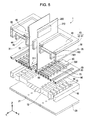
FIG. 4 is an exploded perspective view of the ink jet recording head. -
FIG. 5 is an exploded cross-sectional perspective view of a portion of the ink jet recording head. -
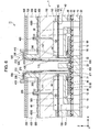
FIG. 6 is a cross-sectional view of the ink jet recording head unit inFIG. 2 , taken along line VI-VI. -
FIG. 7 is a cross-sectional view of the ink jet recording head unit inFIG. 2 , taken along line VII-VII. -
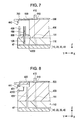
FIG. 8 is a cross-sectional view of an ink jet recording head unit according to a first modification. -
FIG. 9 is a perspective view illustrating a portion of a holder member according to a second modification. - The following description will be given by taking as an example a liquid ejection head unit according to an embodiment, which is installed on a
printer 1000 serving as a liquid ejection apparatus. -
FIG. 1 is a schematic view illustrating the configuration of theprinter 1000. InFIG. 1 , the direction X corresponds to a main scanning direction in which acarriage 2 moves, the direction Y corresponds to a sub-scanning direction in which a recording medium P is transported, and the direction Z is perpendicular to the directions X and Y. When the directions X and Y are on a horizontal plane, the direction Z is the gravity direction. However, depending on how theprinter 1000 is placed, the direction Z may not be the gravity direction. - As illustrated in
FIG. 1 , theprinter 1000 includes an ink jetrecording head unit 11, which serves as a liquid ejection head unit and has a plurality of ink jet recording heads 1 (not shown inFIG. 1 ), acarriage 2, a carriage moving mechanism 3, aplaten roller 4, andink cartridges 5. - The ink jet recording heads 1 are attached to the ink jet
recording head unit 11, on the side facing a recording medium P, such as a recording sheet, (the lower surface in the direction Z inFIG. 1 ) and discharge ink droplets onto the surface of the recording medium P. - The carriage moving mechanism 3 includes a
timing belt 6, a drivingpulley 7, a drivenpulley 8, and amotor 107. Thetiming belt 6, to which thecarriage 2 is attached, is stretched over the drivingpulley 7 and the drivenpulley 8. The drivingpulley 7 is connected to the output shaft of themotor 107. - When the
motor 107 is activated, thecarriage 2, while being guided by aguide rod 9 extending in theprinter 1000, reciprocates in the direction X, which is the main scanning direction. Aplaten roller 4 receives a driving force from amotor 104 and transports a recording medium P in the direction Y, which is the sub-scanning direction. - The
ink cartridges 5, which store ink, are removably attached to thecarriage 2. Theink cartridges 5 supply ink to the ink jet recording heads 1. When multiple colors of ink are to be supplied,multiple ink cartridges 5 are attached to thecarriage 2. InFIG. 1 , tenink cartridges 5 are attached to thecarriage 2. - The thus-configured
printer 1000 can record an image on the recording medium P by discharging ink from the ink jet recording heads 1 attached to thecarriage 2, while reciprocating thecarriage 2 in the direction X by the carriage moving mechanism 3 and transporting the recording medium P in the direction Y by theplaten roller 4. - Referring to
FIGS. 2 and 3A to 3C, the ink jet recording heads 1 and the ink jetrecording head unit 11 will be described. -
FIG. 2 is a perspective view of the ink jetrecording head unit 11 according to an embodiment, andFIGS. 3A to 3C are exploded perspective views of the ink jetrecording head unit 11. -
FIG. 3C illustrates, in a larger scale, only one inkjet recording head 1 before being incorporated into the ink jetrecording head unit 11. In actuality, five ink jet recording heads 1 are incorporated into the ink jetrecording head unit 11. - In
FIGS. 2 and 3A to 3C, each inkjet recording head 1 corresponds to two colors of ink, and hence, ten colors of ink are discharged by five ink jet recording heads 1 in this embodiment. - The number of ink jet recording heads 1 incorporated into the ink jet
recording head unit 11 depends on how many colors of ink are to be discharged, and thus, not limited to five. - The ink jet
recording head unit 11 includes aholder member 400 and arelay substrate 500. - The
holder member 400 has tenink introduction paths 410, which serve as liquid introduction paths, corresponding to five ink jet recording heads 1. Furthermore, therelay substrate 500 hasholes 510, through which theink introduction paths 410 extend. - The
relay substrate 500 is fitted to theholder member 400 from one side thereof, such that theink introduction paths 410 extend through theholes 510. - In
FIG. 3C , the inkjet recording head 1 includes acase head 110, which serves as a support member, and a pair of chip-on-film (COF)substrates 210, which serve as flexible wiring substrates. Furthermore, theCOF substrates 210 each have a plurality ofwires 220 and drivingcircuits 200. - In
FIGS. 2 and 3A to 3C, the ink jet recording heads 1 are fitted to theholder member 400 from the recording medium P side (the lower surface side in the direction Z inFIG. 1 ), i.e., the side opposite to the side provided with therelay substrate 500. Theholder member 400 has fiveholder openings 420 corresponding to the ink jet recording heads 1 to be fitted thereto, and therelay substrate 500 has five slits (openings) 520. The COF substrates 210, forming pairs, are inserted through theholder openings 420 and theslits 520, and thewires 220 are bonded toterminals 530 on therelay substrate 500. - Furthermore, in
FIG. 3C , thecase head 110 hasink introduction paths 111, which serve as liquid introduction paths, that are connected to theink introduction paths 410 to introduce ink into the inkjet recording head 1. Thecase head 110 also hasexternal communication paths 120 that communicate withdamper portions 47 described below (seeFIG. 6 ). -
FIG. 4 is an exploded perspective view of the inkjet recording head 1 before being incorporated into theholder member 400 and therelay substrate 500.FIG. 5 is an exploded cross-sectional perspective view of a portion of the inkjet recording head 1.FIG. 5 does not show thecase head 110. -
FIG. 6 is a cross-sectional view of the ink jetrecording head unit 11 inFIG. 2 , taken along line VI-VI, andFIG. 7 is a cross-sectional view of the ink jetrecording head unit 11 inFIG. 2 , taken along line VII-VII. - In
FIGS. 4 , 5, and 6, the inkjet recording head 1 includes a flow-path forming substrate 10, anozzle plate 20, aprotection substrate 30, acompliance substrate 40, and a pair of theCOF substrates 210 provided with the drivingcircuits 200. - The flow-
path forming substrate 10, thenozzle plate 20, and theprotection substrate 30 are stacked such that the flow-path forming substrate 10 is between thenozzle plate 20 and theprotection substrate 30, and thecompliance substrate 40 is disposed on theprotection substrate 30. - The COF substrates 210 each have a
first end 211 and asecond end 212, which is located opposite thefirst end 211. InFIG. 6 , the first ends 211 of theCOF substrates 210 are inserted through theprotection substrate 30, and the second ends 212 are connected to therelay substrate 500. - The flow-
path forming substrate 10 is made of, for example, a silicon single crystal substrate having a plane direction (110). Anelastic film 50 made of, for example, silicon dioxide is formed on one surface thereof. - The flow-
path forming substrate 10 may be made of a material other than the silicon single crystal substrate, and, for example, a metal plate or a ceramic plate may be used. - The flow-
path forming substrate 10 has a plurality ofpressure generating chambers 12 defined by partition walls and provided in two rows arranged side-by-side in the width direction thereof. Eachpressure generating chamber 12 is paired with a corresponding one in the other row. - Furthermore,
communication portions 13 are provided on the outer side of the rows of thepressure generating chambers 12 in the longitudinal direction thereof, and thecommunication portions 13 communicate with thepressure generating chambers 12 throughink supply paths 14 provided corresponding to the respectivepressure generating chambers 12. Thecommunication portions 13 communicate withsupply portions 101 of theprotection substrate 30, forming portions ofmanifolds 100, which serve as ink chambers each common to a row of thepressure generating chambers 12. - The
ink supply paths 14, which have a smaller width than thepressure generating chambers 12, maintain the flow path resistance for ink flowing from thecommunication portions 13 into thepressure generating chambers 12 constant. - Although the
ink supply paths 14 are formed such that the width of the flow paths is reduced from one side in this embodiment, theink supply paths 14 may be formed such that the width of the flow paths is reduced from both sides. Furthermore, theink supply paths 14 may be formed by reducing the thickness, not the width, of the flow paths. - Furthermore, the
nozzle plate 20 provided withnozzle openings 21, which communicate with ends of thepressure generating chambers 12 opposite the ends provided with theink supply paths 14, is bonded, with an adhesive or a heat welding film, to a surface of the flow-path forming substrate 10 opposite the surface provided with theelastic film 50. In this embodiment, because the flow-path forming substrate 10 is provided with two rows of thepressure generating chambers 12 arranged side-by-side, one inkjet recording head 1 has two rows of thenozzle openings 21 arranged side-by-side. Thenozzle plate 20 is made of, for example, glass ceramic, a silicon single crystal substrate, or stainless steel. - On the other hand, an insulating
film 55 is formed on theelastic film 50 that is formed on the flow-path forming substrate 10. Furthermore,lower electrodes 60 composed of metal, such as platinum (Pt), or metaloxide, such as strontium ruthenate (SrRuO),piezoelectric layers 70 having a perovskite structure, andupper electrodes 80 composed of metal, such as gold (Au) or iridium (Ir), are formed on the insulatingfilm 55, formingpiezoelectric elements 300, which serve as pressure generating elements. - Herein, the
piezoelectric elements 300 refer to portions each include thelower electrode 60, thepiezoelectric layer 70, and theupper electrode 80. Thepiezoelectric elements 300 form pairs corresponding to the pairs of thepressure generating chambers 12. - Furthermore, herein, the
piezoelectric elements 300 and a vibration plate, which is displaced by driving thepiezoelectric elements 300, are collectively referred to as an actuator device. In the example above, theelastic film 50, the insulatingfilm 55, and thelower electrodes 60 serve as the vibration plate. However, it is of course not limited thereto, and it is possible that, for example, only thelower electrodes 60 may serve as the vibration plate, without providing theelastic film 50 and the insulatingfilm 55. Alternatively, thepiezoelectric elements 300 themselves may serve as the vibration plate. - Usually, the
lower electrodes 60 or theupper electrodes 80 of thepiezoelectric elements 300 are used as the common electrode, and the remaining electrodes and thepiezoelectric layers 70 are patterned on thepressure generating chambers 12. Herein, portions that are formed of the patterned electrodes and thepiezoelectric layers 70 and cause piezoelectric strain when a voltage is applied to both electrodes are referred to as piezoelectric active portions. - Although the
lower electrodes 60 are used as the common electrode and theupper electrodes 80 are used as the individual electrodes of thepiezoelectric elements 300 in this embodiment, these functions may be reversed, depending on how the driving circuits and the wires are arranged. In any case, the piezoelectric active portions are formed for the respectivepressure generating chambers 12. - Furthermore, lead
electrodes 90 composed of, for example, gold (Au), which extend over the insulatingfilm 55, are connected to theupper electrodes 80, which serve as individual electrodes, of thepiezoelectric elements 300. Thelead electrodes 90 form pairs corresponding to the pairs of thepiezoelectric elements 300. Ends on one side of thelead electrodes 90 are connected to theupper electrodes 80, and ends on the other side of thelead electrodes 90 extend to positions between the parallel rows of thepiezoelectric elements 300. - Furthermore, the
protection substrate 30 having piezoelectric-elementaccommodating portions 31, which have spaces large enough not to prevent the movement of thepiezoelectric elements 300, in the areas facing thepiezoelectric elements 300 is bonded, with an adhesive 35 or the like, to the top of the flow-path forming substrate 10 provided with thepiezoelectric elements 300. Because thepiezoelectric elements 300 are accommodated in the piezoelectric-elementaccommodating portions 31, thepiezoelectric elements 300 are protected and not affected by the external environment. The piezoelectric-elementaccommodating portions 31 may be either sealed or unsealed. Furthermore, the piezoelectric-elementaccommodating portions 31 may be provided either individually for the respectivepiezoelectric elements 300 or continuously for a plurality ofpiezoelectric elements 300. In this embodiment, the piezoelectric-elementaccommodating portions 31 are continuously provided for a plurality ofpiezoelectric elements 300. - Furthermore, portions of the
manifolds 100, which serve as the common ink chambers (liquid chambers) for a plurality of individual flow paths, are provided in theprotection substrate 30, at portions facing the piezoelectric-elementaccommodating portions 31. In this embodiment, portions of themanifolds 100 are formed in the shape of a recess provided in the surface opposite the surface at which theprotection substrate 30 and the flow-path forming substrate 10 are bonded together. - The
protection substrate 30 has recesses in the surface opposite the surface bonded to the flow-path forming substrate 10, and the openings of the recesses are sealed by thecompliance substrate 40. Note that themanifolds 100 continuously extend in a transverse direction (width direction) of the individual flow paths. - Furthermore, the
manifolds 100 extend up to positions near the ends of theprotection substrate 30 in the longitudinal direction of thepressure generating chambers 12, and the ends of themanifolds 100 on one side are provided at positions facing the ends of the individual flow paths. By providing themanifolds 100 above the piezoelectric-element accommodating portions 31 (in areas overlapping the piezoelectric-elementaccommodating portions 31 in plan view) in this manner, themanifolds 100 do not need to be extended to the outer side of thepressure generating chambers 12 in the longitudinal direction thereof. Thus, the ink jet recording heads 1 can be reduced in size by reducing the width thereof in the longitudinal direction of thepressure generating chambers 12. - Furthermore, a through-
hole 32 penetrating theprotection substrate 30 in the thickness direction is provided substantially at the center of theprotection substrate 30, i.e., the area where the pairedpressure generating chambers 12 face each other. Apartition portion 33 is provided at the center of the through-hole 32. - The other ends of the
lead electrodes 90 opposite the ends connected to theupper electrodes 80 are exposed at the bottom of the through-hole 32. Thelead electrodes 90 exposed in the through-hole 32 are electrically connected to thewires 220, formed on theCOF substrates 210 inserted through the through-hole 32, at the first ends 211. Thelead electrodes 90 are bonded to thewires 220 with, for example, an anisotropic conductive adhesive, ACP600. - Because the use of ACP600 enables a plurality of
lead electrodes 90 to be bonded to oneCOF substrate 210, the processing time can be reduced compared with wire bonding, in which thelead electrodes 90 are sequentially connected to theCOF substrate 210, and hence, the cost can be reduced. - The COF substrates 210 are flexible substrates, and the first ends 211 to be connected to the
lead electrodes 90 are bent in a substantially L shape. The first ends 211 are disposed toward thepiezoelectric elements 300 facing thereto. Thepiezoelectric elements 300 are driven by the drivingcircuits 200 mounted on the COF substrates 210. - The
protection substrate 30 is made of, for example, glass, ceramic material, metal, or resin. It is more preferable that theprotection substrate 30 be made of a material having substantially the same coefficient of thermal expansion as the flow-path forming substrate 10. In this embodiment, theprotection substrate 30 is made of a silicon single crystal substrate, which is the same material as the material of the flow-path forming substrate 10. - The
compliance substrate 40 includes a sealingfilm 41 and a fixingplate 42. The sealingfilm 41 is made of a flexible material having low rigidity, for example, a polyphenylene sulfide (PPS) film having a thickness of about several μm. The fixingplate 42 is made of a hard material, for example, metal, such as a stainless steel (SUS) plate having a thickness of about several tens μm. - In
FIG. 6 , the sealingfilm 41 and the fixingplate 42 are bonded together with abonding adhesive 700. - The fixing
plate 42 is provided around themanifolds 100 in theprotection substrate 30, and areas facing themanifolds 100 serve as fixingplate openings 43, where the fixingplate 42 is completely removed in the thickness direction. - Furthermore, in
FIGS. 4 and 5 , the fixingplate 42 hasprojections 44 protruding into the fixingplate openings 43, and theprojections 44 each have anink introduction port 45 penetrating in the thickness direction, which serves as a liquid introduction port through which ink is supplied from theink cartridge 5 shown inFIG. 1 , where ink is stored, to themanifold 100. - As illustrated in
FIGS. 4 and 5 , in this embodiment, theprojections 44 are provided on the opposite side from thesupply portions 101, such that portions thereof in the direction in which the rows of thepressure generating chambers 12 are arranged protrude up to areas facing themanifolds 100. Therefore, theink introduction ports 45 are provided at ends opposite from thesupply portions 101 provided in theprotection substrate 30, in the longitudinal direction of thepressure generating chambers 12. By providing theink introduction ports 45 at the ends opposite from thesupply portions 101 of theprotection substrate 30 in this manner, the risk of the dynamic pressure of ink introduced from theink cartridges 5 shown inFIG. 1 affecting thepressure generating chambers 12 via thesupply portions 101 can be reduced. - Because of the fixing
plate openings 43 in the fixingplate 42, one surface of each manifold 100 constitutes a deformableflexible portion 46 sealed by theflexible sealing film 41 and thebonding adhesive 700. It is also possible that theflexible portion 46 is made only of the sealingfilm 41. - In this embodiment, the
flexible portions 46 are provided in the areas facing thesupply portions 101 of theprotection substrate 30 in the areas facing themanifolds 100, and around theink introduction ports 45 in the fixingplate 42 in the areas facing themanifolds 100. Theflexible portions 46 are provided in a continuous manner in the areas facing thesupply portions 101 and around theink introduction ports 45. By providing theflexible portions 46 in the areas facing thesupply portions 101 and around theink introduction ports 45, largeflexible portions 46 can be formed. Thus, the compliance in themanifolds 100 can be increased, thereby reliably reducing cross talk caused by the negative influence of pressure fluctuation. - Furthermore, the
case head 110 is provided on thecompliance substrate 40. Thecase head 110 has theink introduction paths 111 communicating with theink introduction ports 45 formed in theprojections 44 shown inFIG. 4 , through which ink is supplied from the ink storage portions, such as theink cartridges 5 shown inFIG. 1 , to themanifolds 100. - Furthermore, the
case head 110 hasrecesses 112 in the areas facing the fixingplate openings 43 to allow appropriate deflection of the fixingplate openings 43. - Furthermore, the
case head 110 has asupport hole 113 communicating with the through-hole 32 provided in theprotection substrate 30. - The first ends 211 of the
COF substrates 210 are inserted through thesupport hole 113 and the through-hole 32, and thewires 220 at the first ends 211 are connected to thelead electrodes 90. - Note that the
COF substrates 210 may be supported by a molding material filled in the through-hole 32 and thesupport hole 113. - Furthermore, in
FIGS. 6 and 7 , thecase head 110 has thedamper portions 47, which serve as damper recesses, in the areas facing the fixingplate openings 43 to allow appropriate deflection of theflexible portions 46. - Furthermore, the
case head 110 has thesupport hole 113 that communicates with the through-hole 32 provided in theprotection substrate 30. - In
FIG. 6 , the second ends 212 of theCOF substrates 210, which are located opposite the first ends 211, are inserted through theholder opening 420 in theholder member 400 and theslit 520 in therelay substrate 500, and thewires 220 at the second ends 212 are connected to theterminals 530 on therelay substrate 500. - In
FIGS. 6 and 7 , theexternal communication paths 120 shown inFIGS. 3 and 4 are formed in thecase head 110 so as to communicate with thedamper portions 47. Theexternal communication paths 120 communicate with airopen holes 450 formed in theholder member 400. - The
case head 110 is made of, for example, resin mainly composed of PPS, or metal. - The
holder member 400 hasbuffer chambers 430 communicating with the airopen holes 450. The airopen holes 450, which have a tubular shape in thebuffer chambers 430, protrude in thebuffer chambers 430 and open in the middle of thebuffer chambers 430. - Furthermore, in
FIG. 7 , thebuffer chambers 430 each have anopening 440 in a side surface of theholder member 400 so as to communicate with the outside. - The
buffer chambers 430 may be formed by providing recesses, which constitute part of thebuffer chambers 430, in theholder member 400 and covering the recesses withlids 700. Thelids 700 are shown also inFIG. 3B . - As described above, the first ends 211 of the
COF substrates 210 are inserted through theholder opening 420, thesupport hole 113, and the through-hole 32, which together serve as the insertion hole, and thewires 220 at the first ends 211 are connected to thelead electrodes 90. - The COF substrates 210 may be supported by filling the through-
hole 32 and thesupport hole 113 with a molding material. - In the ink jet recording heads 1, ink is introduced from the
ink cartridges 5 shown inFIG. 1 . Then, after the inside, specifically, the portions from themanifolds 100 to thenozzle openings 21, is filled with ink, a voltage is applied between thelower electrodes 60 and theupper electrodes 80, which correspond to thepressure generating chambers 12, according to a driving signal from the drivingcircuits 200. Upon being subjected to a voltage, theelastic film 50 and thepiezoelectric layers 70 are deflected, increasing the pressure in thepressure generating chambers 12 and discharging ink droplets from thenozzle openings 21. Examples of the solvent for ink include diethylene glycol diethyl ether and diethylene glycol methylethyl ether. - The driving signal includes, for example, driving signals, such as driving power source signals, for driving the driving IC, and various control signals, such as serial signals (SI). The wires include a plurality of wires for supplying the respective signals.
- This embodiment provides the following advantages.
- (1) Because the
buffer chambers 430 have theopenings 440 oriented in a direction different from the direction in which theholder openings 420, the through-holes 32, and the support holes 113, through which theCOF substrates 210 extend, are open, the ink solvent having reached thebuffer chambers 430 through themanifolds 100 and theflexible portions 46 is discharged in a direction different from the direction in which theholder openings 420 are open. Accordingly, the ink solvent is less likely to reach the connecting portions of thelead electrodes 90 and theCOF substrates 210 through theholder openings 420, the through-holes 32, and the support holes 113, through which theCOF substrates 210 extend. Thus, it is possible to make the solvent take a long time to reach the connecting portion, achieving the ink jet recording heads 1 in which the time taken to cause poor contact between thelead electrodes 90 and theCOF substrates 210 occurs is longer than that in the case where the solvent is discharged in the same direction as the direction in which theholder openings 420 are provided. Furthermore,ink 800 having entered from theopenings 440 in thebuffer chambers 430 stays onbottom surfaces 4300 of thebuffer chambers 430 due to the gravity. Herein, because the openings of the airopen holes 450, through which thedamper portions 47 and thebuffer chambers 430 communicate with each other, are located away from thebottom surfaces 4300 in the direction opposite to the gravity direction, theink 800 is less likely to enter the airopen holes 450. Thus, flow of air into and out of thedamper portions 47 is less likely to be prevented, whereby an ink jetrecording head unit 11 in which pressure fluctuation in themanifolds 100 is smoothly absorbed by theflexible portions 46 can be obtained. - (2) Because portions of the air
open holes 450 protrude in thebuffer chambers 430, theink 800 is less likely to flow from thebottom surfaces 4300 of thebuffer chambers 430 toward the openings of the airopen holes 450. Thus, theink 800 is less likely to enter the airopen holes 450. Thus, flow of air into and out of thedamper portions 47 is even less likely to be prevented, whereby an ink jetrecording head unit 11 in which pressure fluctuation in themanifolds 100 is more smoothly absorbed by theflexible portions 46 can be obtained. - (3) Because the
case head 110, in which a portion of thedamper portions 47 is formed, and theholder member 400, in which thebuffer chambers 430 are formed, are separate members, the portion of thedamper portions 47 and thebuffer chambers 430 are easy to form. Furthermore, the insertion hole, through which theCOF substrates 210 are inserted, can be formed by stacking theprotection substrate 30, thecase head 110, and theholder member 400, which include the through-hole 32 provided in theprotection substrate 30, thesupport hole 113 provided in thecase head 110, and theholder openings 420 provided in theholder member 400. Thus, an easy-to-manufacture ink jetrecording head unit 11 can be obtained. - (4) The
printer 1000 having the above-described advantages can be obtained. -
FIG. 8 is a cross-sectional view of the ink jetrecording head unit 11 according to a first modification, taken along line VIII-VIII inFIG. 2 . - In
FIG. 8 , abuffer chamber 431 is formed in the shape of a recess in a side surface of theholder member 400 and has anopening 441 in the side surface. Thebuffer chamber 431 has astep portion 452 in the direction Z. An airopen hole 451 is formed in thestep portion 452 so as to open in the direction Z (the direction opposite to the gravity direction). - The first modification provides the following advantages.
- (5) The
lids 700 in the embodiment are unnecessary. Thus, an easy-to-manufacture ink jetrecording head unit 11 can be obtained, because the structure of thebuffer chamber 431 is simple. -
FIG. 9 is a perspective view illustrating a portion of aholder member 400 according to a second modification. - In
FIG. 9 , semicircular-column-shapednotches 460 are formed in side surfaces of abuffer chamber 432 formed in the shape of a recess, at positions away from abottom surface 4320 of thebuffer chamber 432 in the direction Z (the direction opposite to the gravity direction). Airopen holes 453 are provided inbottom surfaces 4600 of thenotches 460. Furthermore, anopening 442 is formed in a side surface. - The second modification provides the following advantages.
- (6) The
notches 460 formed in the side surfaces of thebuffer chamber 432 can be formed, as a part of thebuffer chamber 432, simultaneously with the formation of thebuffer chamber 432. Accordingly, an ink jetrecording head unit 11, in which thebuffer chamber 432 is easy to form, can be obtained. Furthermore, because the openings of the airopen holes 453 are enclosed by the side surfaces of thenotches 460, ink is less likely to enter. - Although the embodiment and the modifications have been described above, the invention is not limited thereto. For example, although the ink jet
recording head unit 11 having a plurality of ink jet recording heads 1 has been described in the embodiment, the ink jetrecording head unit 11 may have only one inkjet recording head 1. - Furthermore, the flexible wiring substrates are not limited to the
COF substrates 210, but may be flexible substrates on which no driving circuits are mounted. - Although the above-described embodiment has been described by taking an ink jet recording head unit as an example of the liquid ejection head unit and by taking a printer as an example of the liquid ejection apparatus, the invention can be widely applicable to all kinds of liquid ejection heads and liquid ejection apparatuses, and it is of course applicable to liquid ejection heads and liquid ejection apparatuses used to eject liquid other than ink. Examples of other liquid ejection heads include colorant ejection heads used to manufacture color filters of liquid crystal displays and the like, electrode-material ejection heads used to form electrodes in organic electroluminescent (EL) displays, field emission displays (FED), etc., and living-organic-material ejection heads used to manufacture biochips. The invention is applicable to liquid ejection apparatuses having these liquid ejection heads.
- The entire disclosure of Japanese Patent Application No. 2011-071848, filed Mar. 29, 2011 is incorporated by reference herein.
Claims (8)
Applications Claiming Priority (2)
| Application Number | Priority Date | Filing Date | Title |
|---|---|---|---|
| JP2011-071848 | 2011-03-29 | ||
| JP2011071848A JP5621684B2 (en) | 2011-03-29 | 2011-03-29 | Liquid ejecting head unit and liquid ejecting apparatus |
Publications (2)
| Publication Number | Publication Date |
|---|---|
| US20120249684A1 true US20120249684A1 (en) | 2012-10-04 |
| US8449094B2 US8449094B2 (en) | 2013-05-28 |
Family
ID=46926675
Family Applications (1)
| Application Number | Title | Priority Date | Filing Date |
|---|---|---|---|
| US13/431,853 Expired - Fee Related US8449094B2 (en) | 2011-03-29 | 2012-03-27 | Liquid ejection head unit and liquid ejection apparatus |
Country Status (2)
| Country | Link |
|---|---|
| US (1) | US8449094B2 (en) |
| JP (1) | JP5621684B2 (en) |
Cited By (7)
| Publication number | Priority date | Publication date | Assignee | Title |
|---|---|---|---|---|
| US20140232787A1 (en) * | 2013-02-15 | 2014-08-21 | Seiko Epson Corporation | Liquid Ejecting Head Unit and Liquid Ejecting Apparatus |
| US9475292B2 (en) * | 2015-02-09 | 2016-10-25 | Seiko Epson Corporation | Liquid ejecting head and liquid ejecting apparatus |
| US20160339701A1 (en) * | 2014-03-17 | 2016-11-24 | Seiko Epson Corporation | Liquid ejecting head and liquid ejecting apparatus |
| US20170144438A1 (en) * | 2015-11-24 | 2017-05-25 | Seiko Epson Corporation | Wiring structure, mems device, liquid ejecting head, liquid ejecting apparatus, method for manufacturing mems device, method for manufacturing liquid ejecting head and method for manufacturing liquid ejecting apparatus |
| US10207496B2 (en) | 2016-02-19 | 2019-02-19 | Brother Kogyo Kabushiki Kaisha | Liquid jetting apparatus and wiring member |
| US20190315120A1 (en) * | 2018-04-13 | 2019-10-17 | Toshiba Tec Kabushiki Kaisha | Liquid discharge head and liquid discharge apparatus |
| CN110370806A (en) * | 2018-04-13 | 2019-10-25 | 东芝泰格有限公司 | Fluid ejection head and liquid ejection apparatus |
Families Citing this family (4)
| Publication number | Priority date | Publication date | Assignee | Title |
|---|---|---|---|---|
| JP2014014962A (en) * | 2012-07-06 | 2014-01-30 | Ricoh Co Ltd | Liquid discharge head, and image forming apparatus |
| JP7009857B2 (en) * | 2017-09-13 | 2022-01-26 | セイコーエプソン株式会社 | Liquid injection head, liquid injection device, and piezoelectric device |
| JP7409605B2 (en) * | 2019-12-25 | 2024-01-09 | キヤノン株式会社 | Liquid ejection head and liquid ejection head manufacturing method |
| JP2024071153A (en) * | 2022-11-14 | 2024-05-24 | キヤノン株式会社 | Liquid ejection substrate, liquid ejection head, and method for manufacturing liquid ejection substrate |
Family Cites Families (6)
| Publication number | Priority date | Publication date | Assignee | Title |
|---|---|---|---|---|
| JP2004148509A (en) | 2001-10-04 | 2004-05-27 | Seiko Epson Corp | Liquid jet head |
| JP4285453B2 (en) * | 2001-10-04 | 2009-06-24 | セイコーエプソン株式会社 | Liquid jet head |
| JP4899328B2 (en) | 2005-03-16 | 2012-03-21 | セイコーエプソン株式会社 | Liquid jet head |
| JP5344142B2 (en) * | 2008-03-18 | 2013-11-20 | セイコーエプソン株式会社 | Liquid ejecting head and liquid ejecting apparatus |
| JP5403228B2 (en) * | 2009-03-26 | 2014-01-29 | セイコーエプソン株式会社 | Liquid ejecting head unit and liquid ejecting apparatus |
| JP2010240851A (en) * | 2009-04-01 | 2010-10-28 | Seiko Epson Corp | Droplet discharge head, method for manufacturing droplet discharge head, and droplet discharge apparatus |
-
2011
- 2011-03-29 JP JP2011071848A patent/JP5621684B2/en not_active Expired - Fee Related
-
2012
- 2012-03-27 US US13/431,853 patent/US8449094B2/en not_active Expired - Fee Related
Cited By (16)
| Publication number | Priority date | Publication date | Assignee | Title |
|---|---|---|---|---|
| US20140232787A1 (en) * | 2013-02-15 | 2014-08-21 | Seiko Epson Corporation | Liquid Ejecting Head Unit and Liquid Ejecting Apparatus |
| US9022524B2 (en) * | 2013-02-15 | 2015-05-05 | Seiko Epson Corporation | Liquid ejecting head unit and liquid ejecting apparatus |
| US20160339701A1 (en) * | 2014-03-17 | 2016-11-24 | Seiko Epson Corporation | Liquid ejecting head and liquid ejecting apparatus |
| US9844938B2 (en) * | 2014-03-17 | 2017-12-19 | Seiko Epson Corporation | Liquid ejecting head and liquid ejecting apparatus |
| US10059099B2 (en) * | 2014-03-17 | 2018-08-28 | Seiko Epson Corporation | Liquid ejecting head and liquid ejecting apparatus |
| US9475292B2 (en) * | 2015-02-09 | 2016-10-25 | Seiko Epson Corporation | Liquid ejecting head and liquid ejecting apparatus |
| US20170144438A1 (en) * | 2015-11-24 | 2017-05-25 | Seiko Epson Corporation | Wiring structure, mems device, liquid ejecting head, liquid ejecting apparatus, method for manufacturing mems device, method for manufacturing liquid ejecting head and method for manufacturing liquid ejecting apparatus |
| CN107020842A (en) * | 2015-11-24 | 2017-08-08 | 精工爱普生株式会社 | MEMS device, injector head, injection apparatus and their manufacture method, distribution structure |
| US10207496B2 (en) | 2016-02-19 | 2019-02-19 | Brother Kogyo Kabushiki Kaisha | Liquid jetting apparatus and wiring member |
| US10618277B2 (en) | 2016-02-19 | 2020-04-14 | Brother Kogyo Kabushiki Kaisha | Liquid jetting apparatus and wiring member |
| US10906300B2 (en) | 2016-02-19 | 2021-02-02 | Brother Kogyo Kabushiki Kaisha | Liquid jetting apparatus and wiring member |
| US11618252B2 (en) | 2016-02-19 | 2023-04-04 | Brother Kogyo Kabushiki Kaisha | Liquid jetting apparatus and wiring member |
| US11897261B2 (en) | 2016-02-19 | 2024-02-13 | Brother Kogyo Kabushiki Kaisha | Head and printer |
| US20190315120A1 (en) * | 2018-04-13 | 2019-10-17 | Toshiba Tec Kabushiki Kaisha | Liquid discharge head and liquid discharge apparatus |
| CN110370806A (en) * | 2018-04-13 | 2019-10-25 | 东芝泰格有限公司 | Fluid ejection head and liquid ejection apparatus |
| CN110370805A (en) * | 2018-04-13 | 2019-10-25 | 东芝泰格有限公司 | Fluid ejection head and liquid ejection apparatus |
Also Published As
| Publication number | Publication date |
|---|---|
| JP5621684B2 (en) | 2014-11-12 |
| JP2012206283A (en) | 2012-10-25 |
| US8449094B2 (en) | 2013-05-28 |
Similar Documents
| Publication | Publication Date | Title |
|---|---|---|
| US8449094B2 (en) | Liquid ejection head unit and liquid ejection apparatus | |
| JP6264421B2 (en) | Liquid ejecting head and liquid ejecting apparatus | |
| CN102161268B (en) | Liquid ejection head wiring member,liquid ejection head, and liquid ejection device | |
| US8348394B2 (en) | Liquid ejecting head | |
| US9022524B2 (en) | Liquid ejecting head unit and liquid ejecting apparatus | |
| JP2015120296A (en) | Liquid ejecting head and liquid ejecting device | |
| CN102161267A (en) | Liquid ejection head wiring member and liquid ejection head | |
| JP6471864B2 (en) | Head and liquid ejecting apparatus | |
| JP2009143002A (en) | Liquid ejecting head and liquid ejecting apparatus | |
| JP2017177442A (en) | Head and liquid injection device | |
| JP6859600B2 (en) | Manufacturing method of liquid injection head, liquid injection head unit, liquid injection device and liquid injection head unit | |
| CN101961955B (en) | Liquid spray head and liquid spray device | |
| US8444256B2 (en) | Piezoelectric actuator and liquid ejecting head | |
| JP2015036218A (en) | Liquid ejection device | |
| JP5621683B2 (en) | Liquid ejecting head and liquid ejecting apparatus | |
| US10259221B2 (en) | Element substrate, liquid ejection head, and liquid ejection apparatus | |
| US8141985B2 (en) | Liquid ejecting head, liquid ejecting apparatus, and method for manufacturing liquid ejecting head | |
| JP2012206281A (en) | Liquid ejecting head and liquid ejecting apparatus | |
| JP2012218251A (en) | Liquid jet head, and liquid jet apparatus | |
| JP2020146935A (en) | Liquid jet head and liquid jet device | |
| JP5418346B2 (en) | Droplet ejecting head and droplet ejecting apparatus | |
| JP2011224800A (en) | Liquid ejector and liquid ejection head | |
| JP7098942B2 (en) | Liquid injection head, liquid injection device, and piezoelectric device | |
| JP5754495B2 (en) | Droplet ejecting head and droplet ejecting apparatus | |
| JP2007118265A (en) | Liquid ejecting head and liquid ejecting apparatus |
Legal Events
| Date | Code | Title | Description |
|---|---|---|---|
| AS | Assignment |
Owner name: SEIKO EPSON CORPORATION, JAPAN Free format text: ASSIGNMENT OF ASSIGNORS INTEREST;ASSIGNOR:OKUBO, KATSUHIRO;REEL/FRAME:027940/0887 Effective date: 20120208 |
|
| STCF | Information on status: patent grant |
Free format text: PATENTED CASE |
|
| FPAY | Fee payment |
Year of fee payment: 4 |
|
| MAFP | Maintenance fee payment |
Free format text: PAYMENT OF MAINTENANCE FEE, 8TH YEAR, LARGE ENTITY (ORIGINAL EVENT CODE: M1552); ENTITY STATUS OF PATENT OWNER: LARGE ENTITY Year of fee payment: 8 |
|
| FEPP | Fee payment procedure |
Free format text: MAINTENANCE FEE REMINDER MAILED (ORIGINAL EVENT CODE: REM.); ENTITY STATUS OF PATENT OWNER: LARGE ENTITY |
|
| LAPS | Lapse for failure to pay maintenance fees |
Free format text: PATENT EXPIRED FOR FAILURE TO PAY MAINTENANCE FEES (ORIGINAL EVENT CODE: EXP.); ENTITY STATUS OF PATENT OWNER: LARGE ENTITY |
|
| STCH | Information on status: patent discontinuation |
Free format text: PATENT EXPIRED DUE TO NONPAYMENT OF MAINTENANCE FEES UNDER 37 CFR 1.362 |
|
| FP | Lapsed due to failure to pay maintenance fee |
Effective date: 20250528 |