JP4899328B2 - Liquid jet head - Google Patents
Liquid jet head Download PDFInfo
- Publication number
- JP4899328B2 JP4899328B2 JP2005074720A JP2005074720A JP4899328B2 JP 4899328 B2 JP4899328 B2 JP 4899328B2 JP 2005074720 A JP2005074720 A JP 2005074720A JP 2005074720 A JP2005074720 A JP 2005074720A JP 4899328 B2 JP4899328 B2 JP 4899328B2
- Authority
- JP
- Japan
- Prior art keywords
- passage
- case
- liquid
- case constituent
- constituent members
- Prior art date
- Legal status (The legal status is an assumption and is not a legal conclusion. Google has not performed a legal analysis and makes no representation as to the accuracy of the status listed.)
- Expired - Fee Related
Links
Images


Classifications
-
- B—PERFORMING OPERATIONS; TRANSPORTING
- B41—PRINTING; LINING MACHINES; TYPEWRITERS; STAMPS
- B41J—TYPEWRITERS; SELECTIVE PRINTING MECHANISMS, i.e. MECHANISMS PRINTING OTHERWISE THAN FROM A FORME; CORRECTION OF TYPOGRAPHICAL ERRORS
- B41J2/00—Typewriters or selective printing mechanisms characterised by the printing or marking process for which they are designed
- B41J2/005—Typewriters or selective printing mechanisms characterised by the printing or marking process for which they are designed characterised by bringing liquid or particles selectively into contact with a printing material
- B41J2/01—Ink jet
- B41J2/135—Nozzles
- B41J2/14—Structure thereof only for on-demand ink jet heads
- B41J2/14201—Structure of print heads with piezoelectric elements
- B41J2/14233—Structure of print heads with piezoelectric elements of film type, deformed by bending and disposed on a diaphragm
- B41J2002/14241—Structure of print heads with piezoelectric elements of film type, deformed by bending and disposed on a diaphragm having a cover around the piezoelectric thin film element
-
- B—PERFORMING OPERATIONS; TRANSPORTING
- B41—PRINTING; LINING MACHINES; TYPEWRITERS; STAMPS
- B41J—TYPEWRITERS; SELECTIVE PRINTING MECHANISMS, i.e. MECHANISMS PRINTING OTHERWISE THAN FROM A FORME; CORRECTION OF TYPOGRAPHICAL ERRORS
- B41J2/00—Typewriters or selective printing mechanisms characterised by the printing or marking process for which they are designed
- B41J2/005—Typewriters or selective printing mechanisms characterised by the printing or marking process for which they are designed characterised by bringing liquid or particles selectively into contact with a printing material
- B41J2/01—Ink jet
- B41J2/135—Nozzles
- B41J2/14—Structure thereof only for on-demand ink jet heads
- B41J2002/14362—Assembling elements of heads
Description
本発明は、インクジェット式記録ヘッド等の液体噴射ヘッドに関するものであり、特に、液体流路内の液体の蒸発を抑制して当該液体の粘度上昇を防止する液体噴射ヘッドに関するものである。 The present invention relates to a liquid ejecting head such as an ink jet recording head, and more particularly, to a liquid ejecting head that suppresses evaporation of liquid in a liquid flow path and prevents an increase in viscosity of the liquid.
圧力発生室内の液体に圧力変動を生じさせることでノズル開口から液滴として吐出させる液体噴射ヘッドとしては、例えば、インクジェット式プリンタ等の画像記録装置に用いられるインクジェット式記録ヘッド(以下、単に記録ヘッドという)、液晶ディスプレー等のカラーフィルタの製造に用いられる色材噴射ヘッド、有機EL(Electro Luminescence)ディスプレー、FED(面発光ディスプレー)等の電極形成に用いられる電極材噴射ヘッド、バイオチップ(生物化学素子)の製造に用いられる生体有機物噴射ヘッド等がある。 As a liquid ejecting head for ejecting liquid droplets from a nozzle opening by causing a pressure fluctuation in a liquid in a pressure generating chamber, for example, an ink jet recording head (hereinafter simply referred to as a recording head) used in an image recording apparatus such as an ink jet printer is used. Color material ejection heads used in the manufacture of color filters such as liquid crystal displays, electrode material ejection heads used in the formation of electrodes such as organic EL (Electro Luminescence) displays, FEDs (surface emitting displays), biochips (biochemistry) There are bio-organic matter ejecting heads and the like used for manufacturing the device.
上記記録ヘッドの一例として、複数のノズル開口を列設してなるノズル列が形成されたノズル形成基板、共通液体室(リザーバ)から圧力室を経てノズル開口に至る一連の流路を形成する流路形成基板、共通液体室の開口を封止する封止板を有するキャビティユニットと、圧力室内のインクに圧力変動を生じさせ得る圧力発生源としての圧電素子と、この圧電素子と上記キャビティユニットが取り付けられるケース部材とを備えているものがある。 As an example of the recording head, a nozzle forming substrate on which a nozzle array formed by arranging a plurality of nozzle openings is formed, and a flow that forms a series of flow paths from a common liquid chamber (reservoir) to a nozzle opening through a pressure chamber. A path forming substrate, a cavity unit having a sealing plate for sealing the opening of the common liquid chamber , a piezoelectric element as a pressure generating source capable of causing pressure fluctuation in ink in the pressure chamber, and the piezoelectric element and the cavity unit Some have a case member to be attached.
上記封止板は、例えばステンレス鋼等の金属製の支持板の表面にPPS(ポリフェニレンサルファイド)樹脂フィルムを弾性薄膜部としてラミネートした複合板材によって構成されている。この封止板には、リザーバの一部を封止するコンプライアンス部が設けられている。このコンプライアンス部は、リザーバの開口面に対向する領域の支持板を、例えばエッチング加工等によって除去することにより弾性薄膜部のみとされている。そして、このコンプライアンス部は、圧電素子の駆動時のリザーバ内のインクの圧力変動を吸収するダンパーとして機能する。 The sealing plate is composed of a composite plate material in which a PPS (polyphenylene sulfide) resin film is laminated as an elastic thin film portion on the surface of a metal support plate such as stainless steel. The sealing plate is provided with a compliance portion that seals a part of the reservoir. The compliance portion is made only of an elastic thin film portion by removing the support plate in the region facing the opening surface of the reservoir by, for example, etching. The compliance unit functions as a damper that absorbs pressure fluctuations of ink in the reservoir when the piezoelectric element is driven.
そして、上記ケース部材において、キャビティユニットとの接合面におけるリザーバ(コンプライアンス部)に対応する部分には、リザーバの圧力変動に伴う弾性薄膜部の変形を許容するための逃げ凹部が形成されている。また、このケース部材には、逃げ凹部とヘッド外部とを連通するための大気開放通路が開設されている。この大気開放通路は、コンプライアンス部の作動(弾性薄膜部の変形)に応じて、この逃げ凹部内の空気を外部に放出し、或いは、外部の空気を逃げ凹部内に流入させるための空気用通路である。 In the case member, a recess corresponding to the reservoir (compliance portion) on the joint surface with the cavity unit is formed with a relief recess for allowing deformation of the elastic thin film portion due to pressure fluctuation of the reservoir. The case member is provided with an air release passage for communicating the escape recess and the outside of the head. The air release passage is an air passage for discharging the air in the escape recess to the outside or allowing the external air to flow into the escape recess according to the operation of the compliance portion (deformation of the elastic thin film portion). It is.
ところで、上記構成の記録ヘッドにおいて、使用されない状態が長期間継続した場合、リザーバ内のインクの溶媒が徐々に水蒸気となって弾性薄膜部を透過し、上記の大気開放通路を通じて外部に放出され、これによりインクが増粘する虞がある。このインクの増粘は吐出不良等の不具合の原因となる可能性がある。 By the way, in the recording head having the above configuration, when the unused state continues for a long period of time, the solvent of the ink in the reservoir gradually becomes water vapor and permeates the elastic thin film portion, and is discharged to the outside through the above-described atmospheric release passage. This may increase the viscosity of the ink. This thickening of the ink may cause problems such as ejection failure.
そこで、このような不具合を防止するべく、水蒸気の拡散を抑制可能な程度の通路抵抗に設定された極く狭小な制御通路を、逃げ凹部(ダンパ用凹部)と大気開放通路との間にこれらを連通する状態に介在させたものが提案されている(例えば、特許文献1参照)。この制御通路は、通路抵抗を高めることで弾性薄膜部の水蒸気透過率よりも低い水蒸気透過率となるように設定され、この制御通路の通路抵抗によって、リザーバ内のインクの溶媒の水蒸気拡散が抑制され、これにより、インクの粘度上昇を防止するようになっている。 Therefore, in order to prevent such inconvenience, a very narrow control passage set to a passage resistance that can suppress the diffusion of water vapor is provided between the escape recess (damper recess) and the air release passage. Has been proposed (see, for example, Patent Document 1). This control passage is set so that the water vapor transmission rate is lower than the water vapor transmission rate of the elastic thin film portion by increasing the passage resistance, and the water vapor diffusion of the ink solvent in the reservoir is suppressed by the passage resistance of this control passage. As a result, an increase in the viscosity of the ink is prevented.
上記特許文献1において、制御通路は、封止板のケース部材接合面において圧力室やリザーバ(コンプライアンス部)等のインク流路から外れた領域に、この封止板の面方向に延在する溝として設けられている。しかしながら、上記の水蒸気透過率特性を十分に発揮させるのに必要な制御通路の長さを確保するために、その分の余剰領域を封止板に設ける必要がある。このため、封止板に制御通路を設けることは、記録ヘッドの小型化の制約となっていた。また、予め限られた領域に上記制御通路を設ける場合には、上記必要な通路長さを確保するのは困難であった。
In
また、一般的に、上記のような構造の記録ヘッドでは、ケース部材の材料としては成型の容易性などから合成樹脂が好適に用いられる一方、このケース部材と接合されるキャビティユニットの封止板は、ステンレス鋼等の金属で作製される。このため、これらの部材間には熱膨張率差があり、温度や湿度の変化によって接合部分に応力が発生し、これにより部材間に歪みや剥離が発生する虞がある。そのため、ケース部材とキャビティユニット(封止板)とを接合するための接着剤としてシリコン系接着剤を用いるのが好ましい。このシリコン系接着剤は、接合状態においても柔軟性を発揮するため、このシリコン系接着剤の柔軟性によって接合部分に生じる応力を吸収・緩和することができ、これにより部材間の歪みや剥離等を防止することができる。 In general, in the recording head having the above-described structure, a synthetic resin is preferably used as a material for the case member because of ease of molding, and the sealing plate for the cavity unit joined to the case member. Is made of a metal such as stainless steel. For this reason, there is a difference in coefficient of thermal expansion between these members, and stress is generated in the joint portion due to changes in temperature and humidity, which may cause distortion and peeling between the members. Therefore, it is preferable to use a silicon-based adhesive as an adhesive for joining the case member and the cavity unit (sealing plate). Since this silicon-based adhesive exhibits flexibility even in the bonded state, it can absorb and relieve stress generated in the bonded portion by the flexibility of this silicon-based adhesive. Can be prevented.
ところが、上記特許文献1のように、封止板におけるケース部材との接合面に制御通路を形成する構成の場合、各部材の接合に上記シリコン系接着剤を用いると、この接着剤は流動性が比較的高いため、制御通路に入り込み、この制御通路の機能を阻害する虞がある。そのため、上記特許文献1の発明では、例えば、エポキシ系のシート状接着剤の転写による接合など、選択可能な接合手段が限られてしまっていた。しかしながら、上記シート状の接着剤では、厚さや柔軟性の面で、部材間の接合部分に生じる応力を吸収・緩和するのには適さない。
However, in the case of the configuration in which the control passage is formed on the joint surface of the sealing plate with the case member as in
本発明は、このような事情に鑑みてなされたものであり、その目的は、液体流路内の液体の粘度上昇を防止しつつ、小型化に対応することが可能な液体噴射ヘッドを提供することにある。 The present invention has been made in view of such circumstances, and an object thereof is to provide a liquid jet head that can cope with downsizing while preventing an increase in the viscosity of the liquid in the liquid flow path. There is.
本発明の液体噴射ヘッドは、上記目的を達成するために提案されたものであり、共通液体室から圧力室を通りノズル開口に至る一連の液体流路を形成する流路形成基板、及び、前記共通液体室の開口面を封止する封止板を有するキャビティユニットと、前記圧力室内の液体に圧力変動を発生させることによりこの圧力室内の液体を前記ノズル開口から液滴として吐出させ得る圧力発生源とからなるヘッド本体と、
前記ヘッド本体が取り付けられるケース部材と、を備え、
前記ケース部材は、複数のケース構成部材を積層して構成され、
複数のケース構成部材にはそれぞれ大気開放通路が該ケース構成部材の積層方向を貫通する状態に形成され、
各大気開放通路は、ケース構成部材の積層状態で一連に連通し、前記封止板に伝達される前記液体流路内の液体の圧力変動を開放するように大気開放され、
複数のケース構成部材間の境界面を挟むケース構成部材の少なくとも一方には、大気開放通路よりも通路抵抗が高められた制御通路が、各大気開放通路を連通する状態に形成され、
前記複数のケース構成部材間の前記境界面とは異なる境界面を挟むケース構成部材の少なくとも一方には、大気開放通路よりも通路抵抗が高められた第2の制御通路が形成され、
前記複数のケース構成部材の各大気開放通路と前記制御通路と前記第2の制御通路とが連通する状態に形成されていることを特徴とする。
The liquid ejecting head of the present invention has been proposed to achieve the above object, and includes a flow path forming substrate that forms a series of liquid flow paths from a common liquid chamber to a nozzle opening through a pressure chamber, and Cavity unit having a sealing plate for sealing the opening surface of the common liquid chamber, and pressure generation that can cause the liquid in the pressure chamber to be discharged as droplets from the nozzle opening by generating a pressure fluctuation in the liquid in the pressure chamber A head body composed of a source,
A case member to which the head body is attached,
The case member is configured by laminating a plurality of case constituent members,
The plurality of case components are each formed with an air opening passage through the stacking direction of the case components,
Each atmosphere opening passage communicates in series with the stacked state of the case components, and is opened to the atmosphere so as to release the pressure fluctuation of the liquid in the liquid flow path transmitted to the sealing plate,
At least one of the case constituent members sandwiching the boundary surface between the plurality of case constituent members is formed with a control passage having a passage resistance higher than that of the air release passage so as to communicate with each air release passage .
At least one of the case constituent members sandwiching a boundary surface different from the boundary surface between the plurality of case constituent members is formed with a second control passage having a passage resistance higher than that of the air release passage,
Each of the plurality of case constituent members is formed in a state in which each atmosphere opening passage, the control passage, and the second control passage communicate with each other.
この構成によれば、大気開放通路は、積層した状態で一連に連通するように各ケース構成部材にそれぞれ個別に形成されているので、個々の通路の長さ自体は短くすることができる。これにより、高い精度で各通路を形成することができる。即ち、個々の通路の長さを短くすることで、例えば、ケース部材を合成樹脂を用いて成型する場合には、通路となる空部を成型するピンの曲がりや折れの発生を抑えることができ、また、ステンレス鋼等の金属材料に対するプレス加工によりケース部材を作製する場合には、大気開放通路を形成する際のパンチの曲がりや座屈等を抑制することができ、その結果、各大気開放通路を精度良く容易に形成することができる。
さらに、大気開放通路よりも通路抵抗が高められた制御通路を、ケース構成部材間の境界面を挟むケース構成部材の少なくとも一方に各大気開放通路を連通する状態に設けたので、この制御通路の通路抵抗によって水蒸気の通過量を抑制して、封止板の弾性薄膜部からの液体の水蒸気拡散を抑えることが可能となる。これにより、共通液体室の液体が水蒸気として大気開放通路を通じてヘッド外部に放出されるのを抑制することができる。その結果、液体噴射ヘッドが使用されない状態が長期間継続した場合においても液体流路内の液体の粘度上昇を可及的に抑制することができる。
また、この制御通路は、複数のケース構成部材間の境界において少なくとも一方のケース構成部材に設けられているので、その制御通路の長さや通路断面積、特に長さを、共通インク室等の液体流路の形状や液体噴射ヘッドの大きさに殆ど制約されることなく、水蒸気拡散を抑制し得る通路抵抗となるように設定することができる。したがって、液体噴射ヘッドの小型化にも対応することができる。
さらに、制御通路を、各ケース構成部材間の境界面に設ける構成、即ち、ケース部材とキャビティユニットとの境界面(接合面)から離れた位置に形成する構成であるので、ケース部材とキャビティユニットとを接合するための接合手段として流動性の高い接着剤を使用した場合においてもこの接着剤が制御通路に入り込んで制御通路の機能に障害を与える虞が無い。このため、ケース部材とキャビティユニット(封止板)とを接合するための接合手段の選択肢を広げることができ、例えば、柔軟性の高いシリコン系接着剤等を接合手段として用いることもできる。そして、ケース部材の材料(例えば、合成樹脂)と、キャビティユニットの封止板(例えば、金属)との材料との間に熱膨張率差がある場合において、これらの部材の接合手段としてシリコン系接着剤を用いたときには、このシリコン系接着剤の柔軟性によって接合部分に生じる応力を吸収・緩和することができ、これにより部材間の歪みや剥離等を防止することができる。
According to this configuration, the air opening passages are individually formed in each case constituent member so as to communicate with each other in a stacked state, so that the length of each passage itself can be shortened. Thereby, each passage can be formed with high accuracy. In other words, by shortening the length of each passage, for example, when the case member is molded using synthetic resin, it is possible to suppress the occurrence of bending and bending of the pin that molds the empty portion that becomes the passage. In addition, when producing a case member by pressing a metal material such as stainless steel, it is possible to suppress bending, buckling, and the like of the punch when forming the air release passage. The passage can be easily formed with high accuracy.
Further, since the control passage having a passage resistance higher than that of the open air passage is provided in a state where each open air passage is communicated with at least one of the case constituent members sandwiching the boundary surface between the case constituent members . It is possible to suppress the water vapor diffusion from the elastic thin film portion of the sealing plate by suppressing the amount of water vapor passing through the passage resistance. Thereby, it is possible to suppress the liquid in the common liquid chamber from being discharged outside the head as water vapor through the atmosphere opening passage. As a result, an increase in the viscosity of the liquid in the liquid channel can be suppressed as much as possible even when the state in which the liquid ejecting head is not used continues for a long period of time.
In addition, since the control passage is provided in at least one case constituent member at the boundary between the plurality of case constituent members, the length of the control passage and the passage cross-sectional area, particularly the length, are set to the liquid such as the common ink chamber. The passage resistance can be set so as to suppress the diffusion of water vapor without being substantially restricted by the shape of the flow path or the size of the liquid jet head. Therefore, the liquid ejecting head can be reduced in size.
Furthermore, since the control passage is configured to be provided at the boundary surface between the case component members, that is, to be formed at a position away from the boundary surface (joint surface) between the case member and the cavity unit, the case member and the cavity unit. Even when a highly fluid adhesive is used as a joining means for joining the two, there is no possibility that the adhesive enters the control passage and impedes the function of the control passage. For this reason, the choice of the joining means for joining a case member and a cavity unit (sealing board) can be expanded, for example, a highly flexible silicon adhesive etc. can also be used as a joining means. When there is a difference in coefficient of thermal expansion between the material of the case member (for example, synthetic resin) and the material of the sealing plate (for example, metal) of the cavity unit, silicon-based bonding means for these members When an adhesive is used, it is possible to absorb and relieve stress generated in the joint portion due to the flexibility of the silicon adhesive, thereby preventing distortion and peeling between members.
また、上記構成において、大気開放通路の通路断面積は、制御通路の通路断面積よりも
大きいことが望ましい。
そして、上記構成において、前記封止板は、弾性を有する弾性薄膜部と、この弾性薄膜
部を支持する支持板とにより構成され、共通液体室の開口面に対向する領域は弾性薄膜部
のみとされ、前記ケース部材の前記キャビティユニットと接合される面の弾性薄膜部に対
応する部分には、圧力変動の緩和を阻害しないための逃げ凹部が形成され、前記大気開放
通路は前記逃げ凹部に連通していることが望ましい。
In the above configuration, it is desirable that the passage sectional area of the atmosphere opening passage is larger than the passage sectional area of the control passage.
And in the said structure, the said sealing board is comprised by the elastic thin film part which has elasticity, and the support plate which supports this elastic thin film part, and the area | region which opposes the opening surface of a common liquid chamber is only an elastic thin film part. An escape recess is formed in the portion of the surface of the case member corresponding to the elastic thin film portion that is joined to the cavity unit so as not to inhibit relaxation of pressure fluctuations, and the air release passage communicates with the escape recess. it is desirable to have.
上記構成において、前記弾性薄膜部は、ポリフェニレンサルファイドにより成ることが望ましい。
また、各ケース構成部材において、一方のケース構成部材に、他方のケース構成部材との接合面にボスが突設され、他方のケース構成部材には、前記ボスが挿入されるボス受部が形成され、当該ボス受部に前記ボスを嵌挿することで各ケース構成部材が接合されることが望ましい。
In the above configuration, the elastic thin film portion is preferably made of polyphenylene sulfide.
Also , in each case component member, one case component member has a boss projecting from the joint surface with the other case component member, and the other case component member has a boss receiving portion into which the boss is inserted. It is preferable that the case constituent members are joined by inserting the boss into the boss receiving portion.
以下、本発明を実施するための最良の形態を、添付図面等を参照して説明する。なお、以下に述べる実施の形態では、本発明の好適な具体例として種々の限定がされているが、本発明の範囲は、以下の説明において特に本発明を限定する旨の記載がない限り、これらの態様に限られるものではない。また、以下の説明は、本発明の液体噴射ヘッドとして、インクジェット式記録装置(液体噴射装置の一種)に搭載されるインクジェット式記録ヘッド(以下、単に記録ヘッドという)を例に挙げて行う。 The best mode for carrying out the present invention will be described below with reference to the accompanying drawings. In the embodiments described below, various limitations are made as preferred specific examples of the present invention. However, the scope of the present invention is not limited to the following description unless otherwise specified. However, the present invention is not limited to these embodiments. In the following description, an ink jet recording head (hereinafter simply referred to as a recording head) mounted on an ink jet recording apparatus (a kind of liquid ejecting apparatus) will be described as an example of the liquid ejecting head of the present invention.
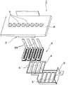
図1は、本実施形態における記録ヘッド1の構成を示す分解斜視図である。本実施形態における記録ヘッド1は、ベースユニット2と、複数のヘッドユニット3と、ヘッドユニット固定板4と、ヘッドカバー5とにより概略構成されている。
ベースユニット2は、内部にヘッドユニット3や集束流路(図示せず)を収容する箱体状部材であり、上面側に針ホルダ6が形成されている。この針ホルダ6は、インク供給針7を取り付けるための板状部材であり、本実施形態においてはインクカートリッジのインク色に対応させて合計8本のインク供給針7がこの針ホルダ6に横並び(ヘッド主走査方向)に配設されている。このインク供給針7は、インクカートリッジ内に挿入される中空針状の部材であり、先端部に開設された導入孔(図示せず)からインクカートリッジ内に貯留されたインクをベースユニット2内の集束流路を通じてヘッドユニット3側に導入するようになっている。
FIG. 1 is an exploded perspective view showing a configuration of a
The
また、ベースユニット2の底面側には、4つのヘッドユニット3が、主走査方向に横並びに位置決めされた状態で、各ヘッドユニット3に対応した4つの開口部4´を有するヘッドユニット固定板4に接合されると共に、同じく各ヘッドユニット3に対応する4つの開口部5´が開設された金属製のヘッドカバー5によって固定される。そして、ヘッドユニット固定板4とヘッドカバー5の各開口部4´,5´からは、各ヘッドユニット3におけるノズル形成基板9のノズル開口14が臨むようになっている。
Further, on the bottom side of the
図2は、本実施形態におけるヘッドユニット3の構成を示す分解斜視図であり、図3は、ヘッドユニット3の短尺方向の断面図である。なお、便宜上、ヘッドユニット3を構成する各部材(ヘッドユニット構成部材)の積層方向を上下方向として説明する。このヘッドユニット3は、ノズル形成基板9、圧力室形成基板10、リザーバ形成基板11、及び、コンプライアンス基板12(本発明における封止板に相当)からなるキャビティユニット8と、圧電素子22と、駆動IC25とを積層した状態でユニットケース13に取り付けて概略構成されており、本発明におけるヘッド本体に相当する。
各ヘッドユニット構成部材には、図2に示すように、ベースユニット2側に設けられた基準ピン(図示せず)に挿通可能な挿通孔Hが、この基準ピンに対応する位置に夫々2箇所ずつ開設されている。そして、各部材は、各々の挿通孔Hに基準ピンを挿通させることで相対的な位置が合わされた上でベースユニット2に固定される。
FIG. 2 is an exploded perspective view showing the configuration of the
As shown in FIG. 2, each head unit component has two insertion holes H that can be inserted into a reference pin (not shown) provided on the
上記ノズル形成基板9は、ドット形成密度に対応したピッチで複数のノズル開口14を列状に開設したステンレス鋼製のプレートである。本実施形態におけるノズル形成基板9には、360dpiのピッチで360個のノズル開口14を列設することで2本のノズル列が構成されている。圧力室形成基板10は、本実施形態においてはシリコン単結晶基板(シリコンウェハー)によって作製され、その表面から異方性エッチングすることによって複数の隔壁で区画された圧力室18が各ノズル開口14に対応して複数形成されている。また、この圧力室形成基板10には、各圧力室18の共通のインク室(共通液体室)としてのリザーバ19の一部を区画する連通空部20が形成されている。この連通空部20は、インク供給路21を介して各圧力室18と連通している。
The
圧力室形成基板10の上面(ノズル形成基板9側とは反対側の面)には、下電極膜と、チタン酸ジルコン酸鉛(PZT)等からなる圧電体層と、上電極膜と(何れも図示せず)を順次積層することで形成された圧電素子22(本発明における圧力発生源に相当)が圧力室18毎に形成されている。この圧電素子22は、所謂撓みモードの圧電素子であり、圧力室18の上部を覆い隠すように形成されている。
A lower electrode film, a piezoelectric layer made of lead zirconate titanate (PZT) or the like, and an upper electrode film (on either side) are formed on the upper surface of the pressure chamber forming substrate 10 (the surface opposite to the nozzle forming substrate 9). A piezoelectric element 22 (corresponding to a pressure generation source in the present invention) formed by sequentially stacking layers is also formed for each
また、圧力室形成基板10上には、基板厚さ方向に貫通したリザーバ部23を有するリザーバ形成基板11が配置される。このリザーバ形成基板11は、圧力室形成基板10と同様にシリコン単結晶基板を用いて作製されている。また、このリザーバ形成基板11におけるリザーバ部23は、圧力室形成基板10の連通空部20と連通してリザーバ19を区画するようになっている。このリザーバ19からインク供給路21及び圧力室18を通りノズル開口14に至るまでのインク流路は、本発明における液体流路に相当する。また、本実施形態におけるノズル形成基板9、リザーバ形成基板11、及び圧力室形成基板10は、本発明における流路形成基板を構成している。
A
リザーバ形成基板11の上面(圧力室形成基板10とは反対側の面)には、各圧電素子22を駆動するための駆動IC25が設けられている。この駆動IC25の各端子は、図示しないボンディングワイヤ等を介して各圧電素子22の個別電極からの引き出し配線と接続されている。そして、駆動IC25の各端子は、TCP(テープキャリアパッケージ)等の配線部材26を介してプリンタ本体側のプリンタコントローラ(図示せず)と電気的に接続され、この配線部材26を介してプリンタコントローラ側から駆動信号等の各種信号が供給されるようになっている。
A
また、リザーバ形成基板11の上面側には、本発明における封止板として機能するコンプライアンス基板12が配置される。このコンプライアンス基板12は、例えばステンレス鋼等の金属製の支持板12aの表面にPPS(ポリフェニレンサルファイド)樹脂フィルムを弾性薄膜部12bとしてラミネートした複合板材によって構成されている。このコンプライアンス基板12には、リザーバ19の開口面を封止するコンプライアンス部12cが設けられている。このコンプライアンス部12cは、リザーバ19の開口面に対向する領域の支持板12aを例えばエッチング加工等によって除去することにより、弾性薄膜部12bのみとされている。そして、このコンプライアンス部12cは、圧電素子22の駆動時のリザーバ19(インク流路)内のインクの圧力変動を緩和(吸収)するダンパーとして機能する。換言すると、コンプライアンス基板12におけるコンプライアンス部12cは、圧電素子22の駆動に伴うインク流路内のインクの圧力変動が積極的に伝達される部分である。
なお、弾性薄膜部12bとしては、上記のPPS樹脂フィルムには限らず、他の樹脂フィルムや、金属製薄膜を利用することもできる。
A
The elastic
図4は、ユニットケース13を下面側(キャビティユニット8との接合面側)から見た平面図、図5は、図4におけるA−A線断面図である。このユニットケース13は、本発明におけるケース部材の一種に相当し、複数のケース構成部材を積層して構成されている。本実施形態におけるユニットケース13は、下面にキャビティユニット8(具体的には、コンプライアンス基板12の支持板12a)が接合される第1ケース構成部材13aと、この第1ケース構成部材13aの上面に接合される第2ケース構成部材13bとの2つのケース構成部材から成っている。各ケース構成部材13a,13bは、厚さ方向を貫通した空部28を中央部に有し、例えば熱可塑性樹脂等の合成樹脂によってノズル列方向に長尺な額縁状にそれぞれ成型されている。なお、空部28は、リザーバ形成基板11上に設けられた駆動IC25を収納可能に設けられており、上記配線部材26がこの空部28を挿通して駆動IC25と接続されるようになっている。
4 is a plan view of the
また、各ケース構成部材13a,13bには、リザーバ19と連通してインク供給針7側からのインクをリザーバ19側に供給するためのインク導入路29が厚さ方向(ケース構成部材の積層方向)を貫通してそれぞれ2つずつ形成されている。このインク導入路29は、各ケース構成部材13a,13bの積層状態で一連に連通し、また、ユニットケース13とキャビティユニット8との接合状態でリザーバ19と連通する。
Also, each
上記第1ケース構成部材13aのキャビティユニット8との接合面(下面)におけるリザーバ19の開口面に対応する領域(コンプライアンス部12cに対応する領域)には、厚さ方向の奥側に窪ませた状態に設けられた逃げ凹部30が形成されている。この逃げ凹部30は、平面視においてリザーバ19の開口部分とほぼ同一の形状と大きさを呈しており、その凹み量(奥行き)は、インク流路内のインクの圧力変動に伴う弾性薄膜部12bの撓み変形を許容可能な程度に設定されている。より具体的には、インク流路内のインクの圧力が最も高まったときの弾性薄膜部12bの逃げ凹部30側への撓み変形を阻害しない程度の寸法に設定されている。つまり、逃げ凹部30は、コンプライアンス部12cによる圧力変動の緩和を阻害しないように設けられている。
A region corresponding to the opening surface of the reservoir 19 (region corresponding to the
また、各ケース構成部材13a,13bには、逃げ凹部30とヘッド外部とを連通するための大気開放通路32(32a,32b)が、各ケース構成部材の厚さ方向を貫通する状態にそれぞれ開設されている。この大気開放通路32は、コンプライアンス部12cの作動(弾性薄膜部12bの変形)に応じて、逃げ凹部30内の空気をヘッド外部に放出し、或いは、外部の空気を逃げ凹部30内に流入させて、逃げ凹部30内の気圧を大気圧に維持するための通路である。この逃げ凹部30を設けることで、コンプライアンス部12cによる圧力変動の緩和機能を、より確実に確保することができる。
Each
第1ケース構成部材13aに設けられた大気開放通路32aの一端は、第2ケース構成部材13bとの接合面(上面)に開口し、また、その他端は、逃げ凹部30の奥面30´の略中央に開口して、この逃げ凹部30と連通しているため、大気開放通路32aのコンプライアンス部12c側の開口部がコンプライアンス部12cの作動によって塞がれてしまうことが無く、確実に逃げ凹部30内の空気をヘッド外部に放出し、或いは、外部の空気を逃げ凹部30内に流入させて、逃げ凹部30内の気圧を大気圧に維持することができる。また、第2ケース構成部材13bの大気開放通路32bは、ノズル列方向(凹部30の長手方向)の位置が大気開放通路32aに対応する位置よりもケース外寄りとなるように形成されており、その一端は、第2ケース構成部材13bの下面(第1ケース構成部材13aとの接合面)に開口し、他端は、第2ケース構成部材13bの上面に開口して大気と連通している。
One end of the
そして、各ケース構成部材13a,13b間の境界面には、大気開放通路32よりも通路抵抗が高められた制御通路33が形成されている。この制御通路33は、第2ケース構成部材13bの下面に、大気開放通路32bの一端から大気開放通路32aの他端に対応する位置に亘って延設された細長い溝状の通路であり、各ケース構成部材13a,13bの大気開放通路32a,32b同士を、ケース構成部材の積層状態で連通するように設けられている。即ち、各大気開放通路32a,32bは、ケース構成部材の積層状態において、制御通路33を間に介在させて一連に連通すると共に逃げ凹部30と連通し、コンプライアンス基板12(コンプライアンス部12c)に伝達されるインク流路内のインクの圧力変動を開放するように大気開放されている。
A
なお、各大気開放通路32a,32bの通路断面積(内寸)は、制御通路33の通路断面積よりも大きく設定されており、コンプライアンス部12cの作動に応じた逃げ凹部30内の空気のスムーズな放出或いは流入に十分な寸法となっている。また、大気開放通路32a,32bの通路断面積を大きくすることで、ケースユニット13とキャビティユニット8との接合に、例えばシリコン系接着剤等の流動性を有する接合手段を用いた場合に、この接着剤が万一大気開放通路32に流入したとしても、この大気開放通路32が接着剤によって完全に塞がれてしまうことを低減することができる。
The passage cross-sectional areas (inner dimensions) of the
一方、上記制御通路33の通路断面積や長さ(総延長)は、その通路抵抗との関係で規定されている。この制御通路33は、その通路抵抗により、リザーバ19から弾性薄膜部12bを水蒸気として透過したインク(詳しくは、インクの溶媒)の通過量を抑制するように機能する。本実施形態においては、この制御通路33における水蒸気透過率特性が、弾性薄膜部12bの水蒸気透過率よりも低くなるように、その通路抵抗が設定されている。ここで、制御通路33に流れる単位時間あたりの水蒸気量Qは、制御通路入口の水蒸気密度をD1、制御通路出口の水蒸気密度をD2、通路抵抗をRとすると、以下の式(1)によって導かれる。
Q=(D1−D2)/R …(1)
ここで、R=L/(c×S)である(L:制御通路33の長さ(総延長)、c:水蒸気の拡散係数、S:制御通路の断面積)。
On the other hand, the passage sectional area and length (total extension) of the
Q = (D1-D2) / R (1)
Here, R = L / (c × S) (L: length of control passage 33 (total extension), c: diffusion coefficient of water vapor, S: cross-sectional area of control passage).
上記(1)式から分かるように、制御通路33の通路抵抗Rを高めることで、制御通路33を流れる水蒸気量Qを抑えることができる。そして、制御通路33の長さLや通路断面積を適切に設定することで、上記特性が得られるような通路抵抗Rを制御通路33に対して付与することができる。したがって、この制御通路33を各大気開放通路32a,32bを連通する状態でケースユニット13に設けることにより、リザーバ19内のインク(溶媒)が水蒸気として大気開放通路32を通じてヘッド外部に放出されるのを抑制することができる。その結果、記録ヘッド1が使用されない状態が長期間継続した場合においてもインク流路内のインクの粘度上昇を可及的に抑制することができる。
As can be seen from the above equation (1), the amount of water vapor Q flowing through the
また、この制御通路33は、複数のケース構成部材13a,13bを積層して成るユニットケース13内に設けているので、その長さLや通路断面積S、特に長さLを、リザーバ19等のインク流路の形状や記録ヘッド1の大きさに殆ど制約されることなく(インク導入路29を避けるのみで足り)、水蒸気拡散を抑制し得る通路抵抗Rとなるように設定することができる。即ち、記録ヘッド1の小型化にも対応することができる。
Further, since the
また、大気開放通路32は、積層した状態で一連に連通するように各ケース構成部材13a,13bにそれぞれ個別に形成されているので、個々の通路の長さ自体は短くすることができる。これにより、高い精度で各大気開放通路32a,32bを形成することができる。即ち、個々の通路の長さを短くすることで、例えば、ユニットケース13(ケース構成部材13a,13b)を合成樹脂を用いて成型する場合には、通路となる空部を形成するピンの曲がりや折れの発生を抑えることができ、また、ステンレス鋼等の金属材料に対するプレス加工によりユニットケース13を作製する場合には、パンチの曲がりや座屈等を抑制することができ、その結果、各大気開放通路32a,32bを精度良く形成することができる。
Moreover, since the
ここで、本実施形態においては、制御通路33を、各ケース構成部材間の境界面に設ける構成、即ち、ユニットケース13とキャビティユニット8との境界面(接合面)から離れた位置に形成する構成であるので、ユニットケース13とキャビティユニット8とを接合するための接合手段として流動性の高い接着剤を使用した場合においても、この接着剤が制御通路33内に流入する虞が少ない。このため、ユニットケース13とキャビティユニット8とを接合するための接合手段の選択肢を広げることができる。例えば、本実施形態において、キャビティユニット8とユニットケース13との接合には、シリコン系接着剤が用いられる。このシリコン系接着剤は、各部材間を接着した状態においても柔軟性を発揮し、このシリコン系接着剤の柔軟性によって接合部分に生じる応力を吸収・緩和することができ、これにより部材間の歪みや剥離等を効果的に防止することができる。
Here, in the present embodiment, the
また、本実施形態におけるケース構成部材13a,13bについては、両者共に同一の合成樹脂によって作製されているので、熱膨張率の差異が殆ど無い。そのため、これらのケース構成部材13a,13bには、例えば、エポキシ系のシート状接着剤の転写による接着が好適である。勿論、ケース構成部材13a,13bを上記シリコン系接着剤を用いて接合することも可能である。また、ケース構成部材13a,13bの両者とも金属によって作成される場合には、樹脂に比べて線膨張係数が低く、また、膨潤の心配が無いため、例えば湿度などの環境が変化しても、ケース構成部材13a,13b間の境界部に形成された制御通路33の大きさが不必要に変化することを防止することができる。また、金属のケース構成部材13a,13bは、樹脂によって構成する場合に比べて剛性が高いため、例えば、ヘッド本体にノズルプレートを接合した際に、ヘッド全体を反らせようとする力が働いた場合においてケース構成部材13a,13bの厚みがあまり無くても、ヘッド全体の反りを抑制することができ、その結果、制御通路33の水蒸気透過抑制機能を発揮するのに必要な通路の大きさも確保できる。
In addition, since the case
以上のように、上記記録ヘッド1では、ユニットケース13内に設けられた制御通路33によって水蒸気の大気への流出が抑制されているので、記録ヘッド1が使用されない状態が長期間継続した場合においてもインク流路内のインクの粘度上昇を可及的に抑制することができる。このため、インクの増粘に起因するインク滴の吐出不良などを低減することが可能となる。
As described above, in the
ところで、本発明は、上記した第1実施形態に限定されるものではなく、特許請求の範囲の記載に基づいて種々の変形が可能である。 By the way, the present invention is not limited to the first embodiment described above, and various modifications can be made based on the description of the scope of claims.
例えば、上記ユニットケース13に関し、上記第1実施形態においては、2つのケース構成部材13a,13bを積層して構成した例を示したが、これには限らず、図6に示す第2実施形態のように、3つ以上のケース構成部材によってユニットケース13を構成することもできる。この図6の例では、ユニットケース13が、3つのケース構成部材13a,13b,13cによって構成されている。
また、上記第1実施形態においては、ユニットケース13に制御通路33を1つだけ設けた例を示したが、例えば、図6の第2実施形態のように、ユニットケース13内に制御通路33を複数設ける構成とすることもできる。この第2実施形態の例では、ケース構成部材13a,13b間の境界面(第2ケース構成部材13bの下面)とケース構成部材13b,13c間の境界面(第3ケース構成部材13cの下面)にそれぞれ制御通路33b,33c(第2の制御通路に相当)が形成されている。このようにすると、個々の通路をより短くすることができ、より高い精度で各通路を形成することができる。
For example, with respect to the
Moreover, in the said 1st Embodiment, although the example which provided only one control channel |
また、上記第1実施形態では、制御通路33を、各ケース構成部材13a,13b間の境界面に設ける例を示したが、これには限らない。例えば、図7に示す第3実施形態のように、制御通路33を、ケース構成部材の厚さ方向を貫通する状態に設けるようにしても良い。この例では、第1ケース構成部材13aの制御通路33の一端は、第1ケース構成部材13aの上面に開口して第2ケース構成部材13bの大気開放通路32と連通し、その他端は、逃げ凹部30の奥面30´に開口して逃げ凹部30と連通する状態に設けられている。
要は、ユニットケース13を構成するケース構成部材のうち、少なくとも1つに制御通路33が形成され、且つ、各ケース構成部材には、大気開放通路32又は制御通路33のうち、少なくとも何れか一方が形成され、各通路32,33がケース構成部材の積層状態で一連に連通して大気開放されていれば良い。
In the first embodiment, the
In short, at least one of the case components constituting the
また、上記第1実施形態では、合成樹脂による成型によってユニットケース13(ケース構成部材13a,13b)を作製する例を示したが、これには限らない。例えば、ステンレス鋼等の金属材料に対するプレス加工によってユニットケース13(ケース構成部材13a,13b)を作製することもできる。この構成によれば、同じくステンレス鋼等の金属によって作製されたコンプライアンス基板12の支持板12aとの熱膨張率を揃えることができ、その結果、温度・湿度変化による各部材間の歪みや剥離を未然に防止することができる。
Moreover, although the example which produces the unit case 13 (
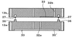
また、上記第1実施形態では、各ケース構成部材13a,13bをシリコン系接着剤やエポキシ系シート状接着剤によって接合する例を示したが、これに限らず、図8に示す第4実施形態のように、接着剤を用いないで各ケース構成部材13a,13b同士を接合する構成を採用することもできる。この構成を採用すれば、ケース構成部材間の境界面に各大気開放通路を連通する状態に設けられた制御通路33に接着剤が流れ込むことが無いため、ケース構成部材の狭い範囲に制御通路33を設けても、この制御通路33が水蒸気拡散機能を十分に発揮することができる。これにより、共通液体室の液体が水蒸気として大気開放通路を通じてヘッド外部に放出されるのを抑制することができる。
図8の例では、一方の第1ケース構成部材13aの上面にボス36が突設され、他方の第2ケース構成部材13bの下面に、第1ケース構成部材13a側のボス36が挿入されるボス受部37が形成されている。これらのボス36とボス受部37の寸法は、接合状態で所謂締り嵌めとなるようにそれぞれ寸法が設定されている。そして、第2ケース構成部材13bのボス受部37に、第1ケース構成部材13aのボス36を嵌挿することで各ケース構成部材13a,13b同士が接合される。
Moreover, although the example which joins each case
In the example of FIG. 8, a
また、以上では、液体噴射ヘッドとして、記録ヘッド1を例に挙げて説明したが、本発明は他の液体噴射ヘッドにも適用することができる。例えば、液晶ディスプレー等のカラーフィルタの製造に用いられる色材噴射ヘッド、有機EL(Electro Luminescence)ディスプレー、FED(面発光ディスプレー)等の電極形成に用いられる電極材噴射ヘッド、バイオチップ(生物化学素子)の製造に用いられる生体有機物噴射ヘッド等にも本発明を適用することができる。
In the above description, the
1 記録ヘッド,2 ベースユニット,3 ヘッドユニット,4 ユニット固定板,5 ヘッドカバー,6 針ホルダ,7 インク供給針,8 キャビティユニット,9 ノズル形成基板,10 圧力室形成基板,11 リザーバ形成基板,12 コンプライアンス基板,13 ユニットケース,14 ノズル開口,18 圧力室,19 リザーバ,20 連通空部,21 インク供給路,22 圧電素子,23 リザーバ部,25 駆動IC,26 配線部材,29 インク導入路,30 逃げ凹部,32 大気開放通路,33 制御通路,36 ボス,37 ボス受部
DESCRIPTION OF
Claims (5)
前記ヘッド本体が取り付けられるケース部材と、を備え、
前記ケース部材は、複数のケース構成部材を積層して構成され、
複数のケース構成部材にはそれぞれ大気開放通路が該ケース構成部材の積層方向を貫通する状態に形成され、
各大気開放通路は、ケース構成部材の積層状態で一連に連通し、前記封止板に伝達される前記液体流路内の液体の圧力変動を開放するように大気開放され、
複数のケース構成部材間の境界面を挟むケース構成部材の少なくとも一方には、大気開放通路よりも通路抵抗が高められた制御通路が、各大気開放通路を連通する状態に形成され、
前記複数のケース構成部材間の前記境界面とは異なる境界面を挟むケース構成部材の少なくとも一方には、大気開放通路よりも通路抵抗が高められた第2の制御通路が形成され、
前記複数のケース構成部材の各大気開放通路と前記制御通路と前記第2の制御通路とが連通する状態に形成されていることを特徴とする液体噴射ヘッド。 A flow path forming substrate for forming a series of liquid flow paths from the common liquid chamber through the pressure chamber to the nozzle opening, a cavity unit having a sealing plate for sealing the opening surface of the common liquid chamber, and the pressure chamber A head main body comprising a pressure generating source capable of causing the liquid in the pressure chamber to be discharged as droplets from the nozzle opening by generating a pressure fluctuation in the liquid of
A case member to which the head body is attached,
The case member is configured by laminating a plurality of case constituent members,
The plurality of case components are each formed with an air opening passage through the stacking direction of the case components,
Each atmosphere opening passage communicates in series with the stacked state of the case components, and is opened to the atmosphere so as to release the pressure fluctuation of the liquid in the liquid flow path transmitted to the sealing plate,
At least one of the case constituent members sandwiching the boundary surface between the plurality of case constituent members is formed with a control passage having a passage resistance higher than that of the air release passage so as to communicate with each air release passage .
At least one of the case constituent members sandwiching a boundary surface different from the boundary surface between the plurality of case constituent members is formed with a second control passage having a passage resistance higher than that of the air release passage,
The liquid ejecting head according to claim 1, wherein each of the plurality of case constituent members is formed in a state in which the atmosphere opening passage, the control passage, and the second control passage communicate with each other.
前記ケース部材の前記キャビティユニットと接合される面の弾性薄膜部に対応する部分には、圧力変動の緩和を阻害しないための逃げ凹部が形成され、
前記大気開放通路は前記逃げ凹部に連通していることを特徴とする請求項1又は請求項2に記載の液体噴射ヘッド。 The sealing plate is composed of an elastic thin film portion having elasticity and a support plate that supports the elastic thin film portion, and the region facing the opening surface of the common liquid chamber is only the elastic thin film portion,
In the portion corresponding to the elastic thin film portion of the surface to be joined to the cavity unit of the case member, a relief recess is formed to prevent the relaxation of pressure fluctuation.
The liquid ejecting head according to claim 1, wherein the air release passage communicates with the escape recess.
Priority Applications (3)
| Application Number | Priority Date | Filing Date | Title |
|---|---|---|---|
| JP2005074720A JP4899328B2 (en) | 2005-03-16 | 2005-03-16 | Liquid jet head |
| US11/376,335 US7510271B2 (en) | 2005-03-16 | 2006-03-16 | Liquid ejection head |
| US12/372,569 US7934813B2 (en) | 2005-03-16 | 2009-02-17 | Liquid ejection head |
Applications Claiming Priority (1)
| Application Number | Priority Date | Filing Date | Title |
|---|---|---|---|
| JP2005074720A JP4899328B2 (en) | 2005-03-16 | 2005-03-16 | Liquid jet head |
Related Child Applications (1)
| Application Number | Title | Priority Date | Filing Date |
|---|---|---|---|
| JP2010176205A Division JP5278392B2 (en) | 2010-08-05 | 2010-08-05 | Liquid jet head |
Publications (3)
| Publication Number | Publication Date |
|---|---|
| JP2006256006A JP2006256006A (en) | 2006-09-28 |
| JP2006256006A5 JP2006256006A5 (en) | 2007-10-18 |
| JP4899328B2 true JP4899328B2 (en) | 2012-03-21 |
Family
ID=37095747
Family Applications (1)
| Application Number | Title | Priority Date | Filing Date |
|---|---|---|---|
| JP2005074720A Expired - Fee Related JP4899328B2 (en) | 2005-03-16 | 2005-03-16 | Liquid jet head |
Country Status (2)
| Country | Link |
|---|---|
| US (2) | US7510271B2 (en) |
| JP (1) | JP4899328B2 (en) |
Families Citing this family (13)
| Publication number | Priority date | Publication date | Assignee | Title |
|---|---|---|---|---|
| JP5391655B2 (en) | 2008-02-20 | 2014-01-15 | セイコーエプソン株式会社 | Liquid ejecting head and liquid ejecting apparatus |
| JP5568854B2 (en) | 2008-03-13 | 2014-08-13 | セイコーエプソン株式会社 | Liquid ejecting head and liquid ejecting apparatus |
| JP5927761B2 (en) * | 2011-02-04 | 2016-06-01 | セイコーエプソン株式会社 | Liquid ejecting head, liquid ejecting apparatus, and method of manufacturing liquid ejecting head |
| JP5741101B2 (en) * | 2011-03-18 | 2015-07-01 | セイコーエプソン株式会社 | Liquid ejecting head, liquid ejecting apparatus, and method of manufacturing liquid ejecting apparatus |
| JP5621684B2 (en) | 2011-03-29 | 2014-11-12 | セイコーエプソン株式会社 | Liquid ejecting head unit and liquid ejecting apparatus |
| JP6066263B2 (en) * | 2012-07-26 | 2017-01-25 | 株式会社リコー | Droplet discharge head and image forming apparatus |
| JP6047986B2 (en) | 2012-08-02 | 2016-12-21 | 株式会社リコー | Droplet discharge head, droplet discharge apparatus, and image forming apparatus |
| US9604459B2 (en) * | 2014-12-15 | 2017-03-28 | Hewlett-Packard Development Company, L.P. | Multi-part printhead assembly |
| JP2017105026A (en) * | 2015-12-08 | 2017-06-15 | エスアイアイ・プリンテック株式会社 | Liquid jet head, liquid jet recording device and method for production of liquid jet head |
| CN112140727B (en) * | 2017-12-27 | 2022-02-18 | 精工爱普生株式会社 | Liquid ejection head and flow channel structure |
| JP7306002B2 (en) * | 2018-07-17 | 2023-07-11 | セイコーエプソン株式会社 | Liquid ejection head and liquid ejection device |
| CN110722880B (en) * | 2018-07-17 | 2021-01-12 | 精工爱普生株式会社 | Head unit and liquid ejecting apparatus |
| JP7131259B2 (en) * | 2018-09-28 | 2022-09-06 | ブラザー工業株式会社 | Liquid ejection head and liquid ejection device |
Family Cites Families (7)
| Publication number | Priority date | Publication date | Assignee | Title |
|---|---|---|---|---|
| JP3061137B2 (en) * | 1989-01-28 | 2000-07-10 | キヤノン株式会社 | Color inkjet recording device |
| JP3620293B2 (en) * | 1998-06-24 | 2005-02-16 | セイコーエプソン株式会社 | Ink jet recording head and method of manufacturing the same |
| JP2002127407A (en) * | 2000-10-25 | 2002-05-08 | Seiko Epson Corp | Ink jet recording head |
| JP2004148509A (en) * | 2001-10-04 | 2004-05-27 | Seiko Epson Corp | Liquid injection head |
| JP4272381B2 (en) * | 2002-02-22 | 2009-06-03 | パナソニック株式会社 | Ink jet head and recording apparatus |
| JP3687662B2 (en) * | 2002-07-05 | 2005-08-24 | セイコーエプソン株式会社 | Liquid jet head |
| JP2003291347A (en) * | 2003-05-16 | 2003-10-14 | Seiko Epson Corp | Liquid ejector and image recorder comprising it |
-
2005
- 2005-03-16 JP JP2005074720A patent/JP4899328B2/en not_active Expired - Fee Related
-
2006
- 2006-03-16 US US11/376,335 patent/US7510271B2/en not_active Expired - Fee Related
-
2009
- 2009-02-17 US US12/372,569 patent/US7934813B2/en not_active Expired - Fee Related
Also Published As
| Publication number | Publication date |
|---|---|
| US20060256159A1 (en) | 2006-11-16 |
| JP2006256006A (en) | 2006-09-28 |
| US7510271B2 (en) | 2009-03-31 |
| US20090160907A1 (en) | 2009-06-25 |
| US7934813B2 (en) | 2011-05-03 |
Similar Documents
| Publication | Publication Date | Title |
|---|---|---|
| JP4899328B2 (en) | Liquid jet head | |
| US7328965B2 (en) | Liquid jet head unit and liquid jet device | |
| JP4438822B2 (en) | Liquid ejecting head and liquid ejecting apparatus | |
| US7553003B2 (en) | Liquid-jet head and liquid-jet apparatus | |
| JP3687662B2 (en) | Liquid jet head | |
| JP5278392B2 (en) | Liquid jet head | |
| US9962934B2 (en) | Liquid ejecting head, liquid ejecting head unit, liquid ejecting apparatus, and method for manufacturing liquid ejecting head unit | |
| JP2011194753A (en) | Liquid ejecting head and liquid ejecting apparatus | |
| JP2006231678A (en) | Liquid jetting head unit and liquid jetting apparatus | |
| JP2009056601A (en) | Liquid jet head and liquid jet apparatus | |
| JP4438821B2 (en) | Liquid ejecting head and liquid ejecting apparatus | |
| JP2004209655A (en) | Liquid injection head | |
| JP5218730B2 (en) | Liquid ejecting head and liquid ejecting apparatus | |
| JP2007030379A (en) | Liquid jet head unit and liquid jet apparatus | |
| JP2007050551A (en) | Liquid jetting head and liquid jetting apparatus | |
| JP5842949B2 (en) | Liquid ejecting head and liquid ejecting apparatus | |
| JP6264549B2 (en) | Liquid ejecting head and liquid ejecting apparatus | |
| JP3589108B2 (en) | Ink jet recording head and ink jet recording apparatus | |
| JP2013028184A (en) | Liquid ejection head | |
| JP4993130B2 (en) | Liquid ejecting head and liquid ejecting apparatus | |
| JP2020110957A (en) | Ink jet head, ink jet device, and manufacturing method of ink jet head | |
| JP2010069689A (en) | Method for manufacturing liquid jetting head, and liquid jetting head | |
| JP6108060B2 (en) | Liquid ejecting head and liquid ejecting apparatus | |
| JP4517917B2 (en) | Liquid jet head | |
| JP4577045B2 (en) | Liquid jet head |
Legal Events
| Date | Code | Title | Description |
|---|---|---|---|
| A521 | Written amendment |
Free format text: JAPANESE INTERMEDIATE CODE: A523 Effective date: 20070831 |
|
| A621 | Written request for application examination |
Free format text: JAPANESE INTERMEDIATE CODE: A621 Effective date: 20070831 |
|
| A977 | Report on retrieval |
Free format text: JAPANESE INTERMEDIATE CODE: A971007 Effective date: 20100603 |
|
| A131 | Notification of reasons for refusal |
Free format text: JAPANESE INTERMEDIATE CODE: A131 Effective date: 20100608 |
|
| A521 | Written amendment |
Free format text: JAPANESE INTERMEDIATE CODE: A523 Effective date: 20100806 |
|
| A131 | Notification of reasons for refusal |
Free format text: JAPANESE INTERMEDIATE CODE: A131 Effective date: 20100914 |
|
| A521 | Written amendment |
Free format text: JAPANESE INTERMEDIATE CODE: A523 Effective date: 20101111 |
|
| A131 | Notification of reasons for refusal |
Free format text: JAPANESE INTERMEDIATE CODE: A131 Effective date: 20101221 |
|
| A521 | Written amendment |
Free format text: JAPANESE INTERMEDIATE CODE: A523 Effective date: 20110221 |
|
| A02 | Decision of refusal |
Free format text: JAPANESE INTERMEDIATE CODE: A02 Effective date: 20110705 |
|
| A521 | Written amendment |
Free format text: JAPANESE INTERMEDIATE CODE: A523 Effective date: 20110927 |
|
| A911 | Transfer to examiner for re-examination before appeal (zenchi) |
Free format text: JAPANESE INTERMEDIATE CODE: A911 Effective date: 20111005 |
|
| TRDD | Decision of grant or rejection written | ||
| A01 | Written decision to grant a patent or to grant a registration (utility model) |
Free format text: JAPANESE INTERMEDIATE CODE: A01 Effective date: 20111206 |
|
| A01 | Written decision to grant a patent or to grant a registration (utility model) |
Free format text: JAPANESE INTERMEDIATE CODE: A01 |
|
| A61 | First payment of annual fees (during grant procedure) |
Free format text: JAPANESE INTERMEDIATE CODE: A61 Effective date: 20111219 |
|
| R150 | Certificate of patent or registration of utility model |
Ref document number: 4899328 Country of ref document: JP Free format text: JAPANESE INTERMEDIATE CODE: R150 Free format text: JAPANESE INTERMEDIATE CODE: R150 |
|
| FPAY | Renewal fee payment (event date is renewal date of database) |
Free format text: PAYMENT UNTIL: 20150113 Year of fee payment: 3 |
|
| S531 | Written request for registration of change of domicile |
Free format text: JAPANESE INTERMEDIATE CODE: R313531 |
|
| R350 | Written notification of registration of transfer |
Free format text: JAPANESE INTERMEDIATE CODE: R350 |
|
| LAPS | Cancellation because of no payment of annual fees |