US20120249120A1 - Current loop detection system and current loop detection method thereof - Google Patents
Current loop detection system and current loop detection method thereof Download PDFInfo
- Publication number
- US20120249120A1 US20120249120A1 US13/154,372 US201113154372A US2012249120A1 US 20120249120 A1 US20120249120 A1 US 20120249120A1 US 201113154372 A US201113154372 A US 201113154372A US 2012249120 A1 US2012249120 A1 US 2012249120A1
- Authority
- US
- United States
- Prior art keywords
- current
- waveform
- characteristic
- connection
- current loop
- Prior art date
- Legal status (The legal status is an assumption and is not a legal conclusion. Google has not performed a legal analysis and makes no representation as to the accuracy of the status listed.)
- Abandoned
Links
Images


Classifications
-
- G—PHYSICS
- G01—MEASURING; TESTING
- G01R—MEASURING ELECTRIC VARIABLES; MEASURING MAGNETIC VARIABLES
- G01R31/00—Arrangements for testing electric properties; Arrangements for locating electric faults; Arrangements for electrical testing characterised by what is being tested not provided for elsewhere
- G01R31/50—Testing of electric apparatus, lines, cables or components for short-circuits, continuity, leakage current or incorrect line connections
- G01R31/58—Testing of lines, cables or conductors
-
- H—ELECTRICITY
- H04—ELECTRIC COMMUNICATION TECHNIQUE
- H04B—TRANSMISSION
- H04B2203/00—Indexing scheme relating to line transmission systems
- H04B2203/54—Aspects of powerline communications not already covered by H04B3/54 and its subgroups
- H04B2203/5462—Systems for power line communications
- H04B2203/5495—Systems for power line communications having measurements and testing channel
Definitions
- the present invention relates to a current loop detection system and a current loop detection method thereof. More particularly, the current loop detection system and the current loop detection method thereof of the present invention can be used to determine a correspondence relationship between a current source and a current loop.
- Electric engineering is now indispensable to people's lives. With enhancement of the awareness of energy-saving and environmental protection, how to utilize the electric power resources more efficiently has become an important topic.
- AMI Advanced Meter Infrastructure
- PLC power line communication
- the PLC technology makes it possible to transmit data through the existing power lines, the cost of additional wiring can be significantly decreased. For this reason, the PLC technology has become one of the most commonly used communication modes in the AMI.
- power line communications are liable to interference, which is especially the case for long-distance communications across different current sources. This degrades the signal quality to a great extent. Therefore, the correspondence relationships between current loops and current sources must be clearly known before PLC-related technologies are used in the AMI.
- PLC testing instruments may be used to determine whether a current source and a current loop correspond to each other according to the communication quality.
- the transmission distance of the PLC is too long, the signal will be attenuated to cause failure of the communication, thus lowering the accuracy of the detection.
- the PLC testing instruments can only perform point-to-point detections and also are very expensive, so it is impossible to perform effective detections at a low cost by use of the PLC testing instruments.
- certain embodiments of the present invention provide a current loop detection system and a current loop detection method thereof.
- the current loop detection system and the current loop detection method thereof determine the correspondence relationship between the current source and the current loop mainly by additionally providing a characteristic load at the current loop end and measuring a current waveform of the characteristic load at the current source end.
- certain embodiments of the present invention provide a current loop detection method for use in a current loop detection system.
- the current loop detection system comprises a characteristic load, a current measuring apparatus and a user apparatus.
- the current measuring apparatus connects to the user apparatus via a first connection.
- the current loop detection method comprises the following steps of: (a) enabling the characteristic load to connect to a current loop electrically, wherein the characteristic load generates a current characteristic waveform while the characteristic load operates; (b) enabling the current measuring apparatus to connect to a current source electrically and to transmit an output current waveform of the current source to the user apparatus via the first connection; (c) enabling the user apparatus to determine that the output current waveform corresponds to the current characteristic waveform; and (d) enabling the user apparatus to determine that the current source connects to the current loop electrically according to a result of the step (c).
- certain embodiments of the present invention also provide a current loop detection system.
- the current loop detection system comprises a characteristic load, a current measuring apparatus and a user apparatus.
- the characteristic load connects to a current loop electrically, and generates a current characteristic waveform while the characteristic load operates.
- the current measuring apparatus connects to a current source electrically.
- the user apparatus connects to the current measuring apparatus via a first connection.
- the current measuring apparatus transmits an output current waveform of the current source to the user apparatus via the first connection.
- the user apparatus determines that the output current waveform corresponds to the current characteristic waveform and, according to a result of the determination, determines that the current source connects to the current loop electrically.
- the current loop detection system and the current loop detection method thereof of the present invention can determine whether the output current waveform of the current source corresponds to the current characteristic waveform generated by the characteristic load when operating. If the answer is “yes”, it means that the current source connects to the current loop electrically.
- FIG. 1A is a schematic view of a first embodiment of the present invention
- FIG. 1B is a schematic view of a current waveform of a current source according to the first embodiment of the present invention
- FIG. 1C is a schematic view of a current waveform of a characteristic load according to the first embodiment of the present invention.
- FIG. 1D is a schematic view of a current waveform of the current source according to the first embodiment of the present invention.
- FIG. 2 is a schematic view of a second embodiment of the present invention.
- FIG. 3 is a schematic view of a third embodiment of the present invention.
- FIG. 4A is a schematic view of a fourth embodiment of the present invention.
- FIG. 4B is a schematic view of current waveforms of current sources according to the fourth embodiment of the present invention.
- FIG. 4C is a schematic view of a current waveform of a characteristic load according to the fourth embodiment of the present invention.
- FIG. 4D is a schematic view of current waveforms of the current sources according to the fourth embodiment of the present invention.
- FIG. 5 is a flowchart of a current loop detection method according to a fifth embodiment of the present invention.
- FIG. 6 is a flowchart of a current loop detection method according to a sixth embodiment of the present invention.
- FIG. 7 is a flowchart of a current loop detection method according to a seventh embodiment of the present invention.
- FIG. 1A there is shown a schematic view of a current loop detection system 1 according to a first embodiment of the present invention.
- the current loop detection system 1 comprises a characteristic load 11 , a current measuring apparatus 13 and a user apparatus 15 .
- the characteristic load 11 connects to a current loop 40 electrically
- the current measuring apparatus 13 connects to a current source 50 electrically
- the user apparatus 15 connects to the current measuring apparatus 13 via a first connection L 1 .
- the current source 50 is a piece of equipment (e.g., a transformer) for supplying a current
- the current loop 40 comprises therein various electric appliances normally used. Functions and interactions of the individual elements will be described in detail hereinafter.
- FIG. 1B there is shown a schematic view of a current waveform of the current source 50 in a stable service status as measured by the current measuring apparatus 13 .
- a user can firstly utilize the user apparatus 15 to obtain, from the current measuring apparatus 13 and via the first connection L 1 , an output current waveform 502 supplied by the current source 50 in the stable service status.
- the current measuring apparatus 13 when connecting to the current source 50 electrically, can measure an output current of the current source 50 in the stable service status and transmit the output current waveform 502 of the output current to the user apparatus 15 via the first connection L 1 so that the current waveform of the current source 50 in the stable service status can be known by the user. It shall be particularly appreciated that, in the normal service status, variations of the total current outputted by the current source 50 shall tend to become stable temporarily, and in this case, the output current waveform 502 of the current received by the user apparatus 15 from the current source 50 shall approximate to a straight line.
- a current characteristic waveform 112 generated by the characteristic load 11 when operating. Specifically, after the testing settings at the current source 50 end have been set, the characteristic load 11 starts to operate and generates the current characteristic waveform 112 when operating. It shall be particularly appreciated that, the characteristic load 11 can operate based on the current characteristic waveform 112 after a predetermined period.
- the current characteristic waveform 112 has a shape that is intended for identification.
- the current characteristic waveform 112 is a square waveform; however, this is not intended to limit the shape of the current characteristic waveform 112 , and in other embodiments, the current characteristic waveform 112 may be one of a sine waveform, a triangle waveform, a pulse waveform and a sawtooth waveform, or any other waveform that can be used for identification purpose.
- the user can know whether a correspondence relationship exists between the current source 50 and the current loop 40 by measuring the current status of the current source 50 by the current measuring apparatus 13 .
- FIG. 1D there is shown an output current waveform 504 measured by the current measuring apparatus 13 and received by the user apparatus 13 via the first connection L 1 continuously.
- the user apparatus 15 determines whether the output current waveform 504 corresponds to (is similar to or consistent with) the current characteristic waveform 112 . Further speaking, assume that the current characteristic waveform 112 is a square waveform. Then, if the output current waveform 504 that is measured also changes into a similar square waveform, it means that the current characteristic waveform 112 generated by the characteristic load 11 in the current loop 40 to which it is connected regularly affects the output current of the current source 50 , so the output current waveform 504 of the current source 50 corresponds to the current characteristic waveform 112 . From this, the user apparatus 15 can determine that the current source 50 and the current loop 40 electrically connect to each other and are located in the same current loop.
- the output current waveform 504 and the current characteristic waveform 112 do not correspond to each other, it means that the output current of the current source 50 is not affected by the current characteristic waveform generated by the characteristic load 11 . Then, it can be known that the current source 50 and the current loop 40 do not electrically connect to each other (i.e., the current source 50 and the current loop 40 are located in different current loops).
- the user apparatus 15 may be a personal computer (PC), a smart phone, a personal digital assistant (PDA), or any other apparatus with calculation and display capabilities.
- the first connection L 1 may be implemented as a wireless connection (including the infrared communication, the Bluetooth, a wireless network and the like) or a wired connection.
- FIG. 2 there is shown a schematic view of a second embodiment of the present invention. Elements used in the second embodiment are identical to those in the first embodiment, so functions of those elements will not be further described herein. It shall be particularly emphasized that, the second embodiment differs from the first embodiment in that, the user apparatus 15 connects to the characteristic load 11 via a second connection L 2 ; i.e., the user apparatus 15 can communicate with the characteristic load 11 via the second connection L 2 .
- the characteristic load 11 automatically starts to operate after the predetermined period.
- the user can manually set the operation of the characteristic load 11 by means of the user apparatus 15 via the second connection L 2 .
- the user can decide the characteristic waveform 112 of the characteristic load 11 to be one of a sine waveform, a triangle waveform, a pulse waveform and a sawtooth waveform via the second connection L 2 ; thus, a waveform that is easy to be identified can be chosen by the user depending on practical conditions.
- the second connection L 2 may be implemented as a wireless connection (including the infrared communication, the Bluetooth, a wireless network and the like) or a wired connection.
- the third embodiment differs from the first embodiment in that, the current measuring apparatus 13 connects to the characteristic load 11 via a second connection L 2 ′; i.e., the current measuring apparatus 13 can communicate with the characteristic load 11 via the second connection L 2 ′ so that the user apparatus 15 can communicate with the characteristic load 11 through the current measuring apparatus 13 via the first connection L 1 and the second connection L 2 ′.
- the characteristic load 11 automatically starts to operate after the predetermined period.
- the user can utilize the user apparatus 15 to manually set the operation of the characteristic load 11 through the current measuring apparatus 13 via the first connection L 1 and the second connection L 2 ′.
- the user can also utilize the user apparatus 15 to decide the characteristic waveform 112 of the characteristic load 11 to be one of a sine waveform, a triangle waveform, a pulse waveform and a sawtooth waveform through the current measuring apparatus 13 via the first connection L 1 and the second connection L 2 ′; thus, a waveform that is easy to be identified can be chosen by the user according to practical conditions.
- the second connection L 2 ′ may be implemented as a wireless connection (including the infrared communication, the Bluetooth, a wireless network and the like) or a wired connection.
- the current loop detection system of the present invention can also measure correspondence relationships of multiple groups of current sources and current loops simultaneously.
- FIG. 4A there is shown a schematic view of a current loop detection system 4 according to a fourth embodiment of the present invention.
- the current loop detection system 4 comprises a characteristic load 41 , a plurality of current measuring apparatuses 431 , 433 , 435 and a user apparatus 45 .
- the characteristic load 41 connects to a current loop 60 electrically, the current measuring apparatuses 431 , 433 , 435 electrically connect to a plurality of current sources 701 , 703 , 705 respectively, and the user apparatus 45 connects to the current measuring apparatuses 431 , 433 , 435 via first connections M 1 , M 2 , M 3 respectively.
- Each of the current sources 701 , 703 , 705 is a piece of equipment (e.g., a transformer) for supplying a current, and the current loop 60 comprises therein various electric appliances that are normally used. Functions and interactions of the individual elements will be described in detail hereinafter.
- each of the current waveforms 7010 , 7030 , 7050 in the fourth embodiment may also approximate to a straight line as a result of a stable total current outputted by each of the current sources 701 , 703 , 705 respectively.
- a current characteristic waveform 412 generated by the characteristic load 41 when operating. Specifically, after the testing settings at the end of each of the current sources 701 , 703 , 705 have been set, the characteristic load 41 starts to operate and generates the current characteristic waveform 412 when operating. Likewise, the characteristic load 41 can operate based on the current characteristic waveform 412 after a predetermined period.
- the current characteristic waveform 412 has a shape intended for identification.
- the current characteristic waveform 412 is a square waveform; however, this is not intended to limit the shape of the current characteristic waveform 412 , and in other embodiments, the current characteristic waveform 412 may be one of a sine waveform, a triangle waveform, a pulse waveform and a sawtooth waveform, or any other waveform that can be used for identification purpose.
- the user can know a correspondence relationship between each of the current sources 701 , 703 , 705 and the current loop 60 by measuring the current status of each of the current sources 701 , 703 , 705 by each of the current measuring apparatuses 431 , 433 , 435 .
- FIG. 4D there are shown output current waveforms 7012 , 7032 , 7052 that are measured by the current measuring apparatuses 431 , 433 , 435 and continuously received by the user apparatus 30 via the first connections M 1 , M 2 , M 3 respectively.
- the user apparatus 45 determines which one of the output current waveforms 7012 , 7032 , 7052 corresponds to the current characteristic waveform 412 .
- it is the output current waveform 7012 that corresponds to the current characteristic waveform 412 .
- the current characteristic waveform 412 generated by the characteristic load 41 in the current loop 60 to which it is connected regularly affects the current outputted by the current source 701 so that the output current waveform 7012 of the current source 701 corresponds to the current characteristic waveform 412 . From this, the user apparatus 45 can determine that the current source 701 electrically connects to the current loop 60 and is located in the same current loop as the current loop 60 .
- neither of the output current waveforms 7032 , 7052 corresponds to the current characteristic waveform 412 , and this means that the output currents of the current sources 703 , 705 are not affected by the current characteristic waveform generated by the characteristic load 41 .
- neither of the current sources 703 , 705 connects to the current loop 60 electrically (i.e., the current sources 703 , 705 are both located in other current loops than the current loop 60 ).
- a fifth embodiment of the present invention is a current loop detection method, a flowchart of which is shown in FIG. 5 .
- the method of the fifth embodiment is for use in a current loop detection system (e.g., the current loop detection system 1 described in the first embodiment).
- the current loop detection system comprises a characteristic load, a current measuring apparatus and a user apparatus.
- the current measuring apparatus connects to the user apparatus via a first connection. Detailed steps of the current loop detection method are described as follows.
- step 501 is executed to enable the characteristic load to connect to a current loop electrically.
- step 502 is executed to enable the characteristic load to operate after a predetermined period.
- the characteristic load generates a current characteristic waveform while operating.
- step 503 is executed to enable the current measuring apparatus to connect to a current source electrically and transmit an output current waveform of the current source to the user apparatus via the first connection.
- the order of the step 502 may be exchanged with that of the step 503 ; i.e., the step 503 may be firstly executed to set the settings of the current source end, and then the step 502 is executed to activate the characteristic load to operate.
- step 504 is executed to enable the user apparatus to determine whether the output current waveform corresponds to (is similar to or consistent with) the current characteristic waveform. If a result of the determination in the step 504 is “yes”, it means that the current characteristic waveform generated by the characteristic load in the current loop to which it is connected can regularly affect the current outputted by the current source so that the output current waveform of the current source corresponds to (is similar to or consistent with) the current characteristic waveform. Then, step 505 is executed to determine that the current source and the current loop electrically connect to each other and are located in the same current loop.
- step 504 determines whether the current outputted by the current source is not affected by the current characteristic waveform generated by the characteristic load in the current loop to which it is connected.
- step 506 is executed to determine that the current source and the current loop do not electrically connect to each other and are located in different current loops.
- a sixth embodiment of the present invention is a current loop detection method, a flowchart of which is shown in FIG. 6 .
- the method of the sixth embodiment is for use in a current loop detection system (e.g., the current loop detection system 1 described in the second embodiment).
- the current loop detection system comprises a characteristic load, a current measuring apparatus and a user apparatus.
- the current measuring apparatus connects to the user apparatus via a first connection, and the user apparatus connects to the characteristic load via a second connection.
- Detailed steps of the current loop detection method are described as follows.
- step 601 is executed to enable the characteristic load to connect to a current loop electrically.
- step 602 is executed to enable the user apparatus to decide a current characteristic waveform of the characteristic load via the second connection and enable the characteristic load to operate based on the current characteristic waveform.
- step 603 is executed to enable the current measuring apparatus to connect to a current source electrically and transmit an output current waveform of the current source to the user apparatus via the first connection.
- the order of the step 602 may also be exchanged with that of the step 603 ; i.e., the step 603 may be firstly executed to set the settings of the current source end, and then the step 602 is executed to activate the characteristic load to operate.
- step 604 is executed to enable the user apparatus to determine whether the output current waveform corresponds to (is similar to or consistent with) the current characteristic waveform. If a result of the determination in the step 604 is “yes”, it means that the current characteristic waveform generated by the characteristic load in the current loop to which it is connected can regularly affect the current outputted by the current source so that the output current waveform of the current source corresponds to (is similar to or consistent with) the current characteristic waveform. Then, step 605 is executed to determine that the current source and the current loop electrically connect to each other and are located in the same current loop.
- step 604 determines whether the current outputted by the current source is not affected by the current characteristic waveform generated by the characteristic load in the current loop to which it is connected. Then, step 606 is executed to determine that the current source and the current loop do not electrically connect to each other and are located in different current loops.
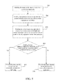
- a seventh embodiment of the present invention is a current loop detection method, a flowchart of which is shown in FIG. 7 .
- the method of the seventh embodiment is for use in a current loop detection system (e.g., the current loop detection system 1 described in the third embodiment).
- the current loop detection system comprises a characteristic load, a current measuring apparatus and a user apparatus.
- the current measuring apparatus connects to the user apparatus via a first connection, and connects to the characteristic load via a second connection.
- Detailed steps of the current loop detection method are described as follows.
- step 701 is executed to enable the characteristic load to connect to a current loop electrically.
- step 702 is executed to enable the user apparatus to decide a current characteristic waveform of the characteristic load by means of the current measuring apparatus via the first connection and the second connection, and enable the characteristic load to operate based on the current characteristic waveform.
- step 703 is executed to enable the current measuring apparatus to connect to a current source electrically and transmit an output current waveform of the current source to the user apparatus via the first connection. It shall be particularly appreciated that, the order of the step 702 may be exchanged with that of the step 703 ; i.e., the step 703 may be firstly executed to set the settings of the current source end, and then the step 702 is executed to activate the characteristic load to operate.
- step 704 is executed to enable the user apparatus to determine whether the output current waveform corresponds to (is similar to or consistent with) the current characteristic waveform. If a result of the determination in the step 704 is “yes”, it means that the current characteristic waveform generated by the characteristic load in the current loop to which it is connected can regularly affect the current outputted by the current source so that the output current waveform of the current source corresponds to (is similar to or consistent with) the current characteristic waveform. Then, step 705 is executed to determine that the current source and the current loop electrically connect to each other and are located in the same current loop.
- step 704 determines whether the current outputted by the current source is not affected by the current characteristic waveform generated by the characteristic load in the current loop to which it is connected.
- step 706 is executed to determine that the current source and the current loop do not electrically connect to each other and are located in different current loops.
- the current loop detection system and the current loop detection method of the present invention can determine a correspondence relationship between a current source and a current loop effectively and correctly at a low cost.
- the disadvantages of the conventional manual detection or the conventional method of employing PLC testing instruments for detection can be easily overcome, and detection of the current loop can be accomplished more efficiently.
Landscapes
- Physics & Mathematics (AREA)
- General Physics & Mathematics (AREA)
- Measurement Of Current Or Voltage (AREA)
Applications Claiming Priority (2)
| Application Number | Priority Date | Filing Date | Title |
|---|---|---|---|
| TW100110946 | 2011-03-30 | ||
| TW100110946A TWI431295B (zh) | 2011-03-30 | 2011-03-30 | 電流迴路檢測系統及其電流迴路檢測方法 |
Publications (1)
| Publication Number | Publication Date |
|---|---|
| US20120249120A1 true US20120249120A1 (en) | 2012-10-04 |
Family
ID=46845546
Family Applications (1)
| Application Number | Title | Priority Date | Filing Date |
|---|---|---|---|
| US13/154,372 Abandoned US20120249120A1 (en) | 2011-03-30 | 2011-06-06 | Current loop detection system and current loop detection method thereof |
Country Status (4)
| Country | Link |
|---|---|
| US (1) | US20120249120A1 (zh) |
| CN (1) | CN102735956B (zh) |
| FR (1) | FR2973514B1 (zh) |
| TW (1) | TWI431295B (zh) |
Families Citing this family (4)
| Publication number | Priority date | Publication date | Assignee | Title |
|---|---|---|---|---|
| TWI497437B (zh) * | 2013-11-25 | 2015-08-21 | Inst Information Industry | 先進讀表基礎建設場勘系統 |
| TWI565952B (zh) * | 2015-08-14 | 2017-01-11 | 國立虎尾科技大學 | 微型多節點電力監控系統 |
| CN105118281B (zh) * | 2015-09-22 | 2018-11-13 | 杭州华春科技有限公司 | 户表关系识别装置及方法 |
| CN110658369A (zh) * | 2019-09-24 | 2020-01-07 | 深圳供电局有限公司 | 剩余电流模拟生成装置及剩余电流动作保护系统 |
Citations (6)
| Publication number | Priority date | Publication date | Assignee | Title |
|---|---|---|---|---|
| US20040201393A1 (en) * | 2003-04-09 | 2004-10-14 | Keisoku Giken Co., Ltd. | Electronic load apparatus |
| US7126831B2 (en) * | 2003-05-23 | 2006-10-24 | Rohm Co. Ltd. | DC-AC converter, and method for supplying AC power |
| US7436299B2 (en) * | 2001-03-02 | 2008-10-14 | Elesys North America Inc. | Vehicle occupant detection using relative impedance measurements |
| US20090212729A1 (en) * | 2008-02-27 | 2009-08-27 | Enfield Technologies, Llc | Method and device for controlling load and voltage in voice coils |
| US20120080944A1 (en) * | 2006-03-28 | 2012-04-05 | Wireless Environment, Llc. | Grid Shifting System for a Lighting Circuit |
| US20120262093A1 (en) * | 2011-04-15 | 2012-10-18 | Recker Michael V | Lighting device capable of maintaining light intensity in demand response applications |
Family Cites Families (3)
| Publication number | Priority date | Publication date | Assignee | Title |
|---|---|---|---|---|
| JP3748521B2 (ja) * | 2001-05-30 | 2006-02-22 | 三菱電機株式会社 | 負荷電流検出方法および装置と電動パワーステアリング装置 |
| JP2008026025A (ja) * | 2006-07-18 | 2008-02-07 | Toyota Motor Corp | 断線検出回路を備えた電源供給回路 |
| US7714587B2 (en) * | 2007-06-29 | 2010-05-11 | Caterpillar Inc. | Systems and methods for detecting a faulty ground strap connection |
-
2011
- 2011-03-30 TW TW100110946A patent/TWI431295B/zh not_active IP Right Cessation
- 2011-05-26 CN CN201110150753.7A patent/CN102735956B/zh active Active
- 2011-06-06 US US13/154,372 patent/US20120249120A1/en not_active Abandoned
- 2011-06-24 FR FR1155656A patent/FR2973514B1/fr not_active Expired - Fee Related
Patent Citations (6)
| Publication number | Priority date | Publication date | Assignee | Title |
|---|---|---|---|---|
| US7436299B2 (en) * | 2001-03-02 | 2008-10-14 | Elesys North America Inc. | Vehicle occupant detection using relative impedance measurements |
| US20040201393A1 (en) * | 2003-04-09 | 2004-10-14 | Keisoku Giken Co., Ltd. | Electronic load apparatus |
| US7126831B2 (en) * | 2003-05-23 | 2006-10-24 | Rohm Co. Ltd. | DC-AC converter, and method for supplying AC power |
| US20120080944A1 (en) * | 2006-03-28 | 2012-04-05 | Wireless Environment, Llc. | Grid Shifting System for a Lighting Circuit |
| US20090212729A1 (en) * | 2008-02-27 | 2009-08-27 | Enfield Technologies, Llc | Method and device for controlling load and voltage in voice coils |
| US20120262093A1 (en) * | 2011-04-15 | 2012-10-18 | Recker Michael V | Lighting device capable of maintaining light intensity in demand response applications |
Non-Patent Citations (3)
| Title |
|---|
| Hung - TW1300134, patent application, - PTO 2014-3379, human translation * |
| Wu - TW 201000933 machine translation, p. 1-11 * |
| You - TW I307778, patent application - PTO 2014-3381, human translation * |
Also Published As
| Publication number | Publication date |
|---|---|
| FR2973514B1 (fr) | 2014-01-10 |
| FR2973514A1 (fr) | 2012-10-05 |
| CN102735956B (zh) | 2014-08-13 |
| CN102735956A (zh) | 2012-10-17 |
| TWI431295B (zh) | 2014-03-21 |
| TW201239372A (en) | 2012-10-01 |
Similar Documents
| Publication | Publication Date | Title |
|---|---|---|
| CN102129061A (zh) | 三相仿真电能表自动接线检测装置及方法 | |
| US7923988B2 (en) | Test equipment and test system using the same | |
| CN104965147A (zh) | 低压用户电能表串户检测系统及检测方法 | |
| CN102088714A (zh) | 测试系统及其功率校准方法 | |
| US20120249120A1 (en) | Current loop detection system and current loop detection method thereof | |
| CN101598605A (zh) | 电缆头温度在线监测系统 | |
| CN206757028U (zh) | 一种三相电能表错误接线检测装置 | |
| CN114006632B (zh) | 一种地面电子单元leu的测试方法及系统 | |
| CN102455688A (zh) | 定位水浸控制系统 | |
| US20150145689A1 (en) | Advanced metering infrastructure site survey system | |
| CN215263968U (zh) | 一种电缆对线器 | |
| CN102253288A (zh) | E1接口阻抗测试装置及系统 | |
| CN108123751A (zh) | 光缆故障快速定位的方法、设备及系统 | |
| CN207184482U (zh) | 光缆纤序及衰耗检测仪 | |
| CN204967820U (zh) | 基于fpga与无线通讯技术的嵌入式光时域反射仪 | |
| CN103701660A (zh) | 一种以太网设备连接装置及其应用的测试系统及方法 | |
| CN117394931A (zh) | 一种用于双模通信模块的检测系统及方法 | |
| CN204116529U (zh) | 电缆异常智能检测系统 | |
| CN104076320A (zh) | 电能表自动检测系统 | |
| CN210609169U (zh) | 一种基于载波通信的低压电缆路径探测仪 | |
| CN106448098A (zh) | 一种电子测量仪器无线程控测试系统及方法 | |
| JP2011085553A (ja) | 光損失測定方法および光損失測定装置 | |
| CN111585670A (zh) | 无线检测系统的检测方法及检测系统 | |
| CN113030788A (zh) | 一种电缆对线器 | |
| CN112953658A (zh) | 一种无线信号测试方法及装置 |
Legal Events
| Date | Code | Title | Description |
|---|---|---|---|
| AS | Assignment |
Owner name: INSTITUTE FOR INFORMATION INDUSTRY, TAIWAN Free format text: ASSIGNMENT OF ASSIGNORS INTEREST;ASSIGNORS:LO, PI-CHUAN;CHANG, SHU-LI;REEL/FRAME:026397/0795 Effective date: 20110601 |
|
| STCB | Information on status: application discontinuation |
Free format text: ABANDONED -- FAILURE TO RESPOND TO AN OFFICE ACTION |