US20120249114A1 - Constant current generation circuit and microprocessor including the same - Google Patents
Constant current generation circuit and microprocessor including the same Download PDFInfo
- Publication number
- US20120249114A1 US20120249114A1 US13/427,359 US201213427359A US2012249114A1 US 20120249114 A1 US20120249114 A1 US 20120249114A1 US 201213427359 A US201213427359 A US 201213427359A US 2012249114 A1 US2012249114 A1 US 2012249114A1
- Authority
- US
- United States
- Prior art keywords
- variation
- voltage
- gradient
- temperature
- current
- Prior art date
- Legal status (The legal status is an assumption and is not a legal conclusion. Google has not performed a legal analysis and makes no representation as to the accuracy of the status listed.)
- Granted
Links
Images


Classifications
-
- G—PHYSICS
- G05—CONTROLLING; REGULATING
- G05F—SYSTEMS FOR REGULATING ELECTRIC OR MAGNETIC VARIABLES
- G05F3/00—Non-retroactive systems for regulating electric variables by using an uncontrolled element, or an uncontrolled combination of elements, such element or such combination having self-regulating properties
- G05F3/02—Regulating voltage or current
- G05F3/08—Regulating voltage or current wherein the variable is DC
- G05F3/10—Regulating voltage or current wherein the variable is DC using uncontrolled devices with non-linear characteristics
- G05F3/16—Regulating voltage or current wherein the variable is DC using uncontrolled devices with non-linear characteristics being semiconductor devices
- G05F3/20—Regulating voltage or current wherein the variable is DC using uncontrolled devices with non-linear characteristics being semiconductor devices using diode- transistor combinations
- G05F3/26—Current mirrors
- G05F3/262—Current mirrors using field-effect transistors only
-
- G—PHYSICS
- G05—CONTROLLING; REGULATING
- G05F—SYSTEMS FOR REGULATING ELECTRIC OR MAGNETIC VARIABLES
- G05F1/00—Automatic systems in which deviations of an electric quantity from one or more predetermined values are detected at the output of the system and fed back to a device within the system to restore the detected quantity to its predetermined value or values, i.e. retroactive systems
- G05F1/10—Regulating voltage or current
- G05F1/46—Regulating voltage or current wherein the variable actually regulated by the final control device is DC
- G05F1/56—Regulating voltage or current wherein the variable actually regulated by the final control device is DC using semiconductor devices in series with the load as final control devices
- G05F1/561—Voltage to current converters
-
- G—PHYSICS
- G05—CONTROLLING; REGULATING
- G05F—SYSTEMS FOR REGULATING ELECTRIC OR MAGNETIC VARIABLES
- G05F3/00—Non-retroactive systems for regulating electric variables by using an uncontrolled element, or an uncontrolled combination of elements, such element or such combination having self-regulating properties
- G05F3/02—Regulating voltage or current
- G05F3/08—Regulating voltage or current wherein the variable is DC
- G05F3/10—Regulating voltage or current wherein the variable is DC using uncontrolled devices with non-linear characteristics
- G05F3/16—Regulating voltage or current wherein the variable is DC using uncontrolled devices with non-linear characteristics being semiconductor devices
- G05F3/20—Regulating voltage or current wherein the variable is DC using uncontrolled devices with non-linear characteristics being semiconductor devices using diode- transistor combinations
- G05F3/24—Regulating voltage or current wherein the variable is DC using uncontrolled devices with non-linear characteristics being semiconductor devices using diode- transistor combinations wherein the transistors are of the field-effect type only
- G05F3/242—Regulating voltage or current wherein the variable is DC using uncontrolled devices with non-linear characteristics being semiconductor devices using diode- transistor combinations wherein the transistors are of the field-effect type only with compensation for device parameters, e.g. channel width modulation, threshold voltage, processing, or external variations, e.g. temperature, loading, supply voltage
- G05F3/245—Regulating voltage or current wherein the variable is DC using uncontrolled devices with non-linear characteristics being semiconductor devices using diode- transistor combinations wherein the transistors are of the field-effect type only with compensation for device parameters, e.g. channel width modulation, threshold voltage, processing, or external variations, e.g. temperature, loading, supply voltage producing a voltage or current as a predetermined function of the temperature
-
- H—ELECTRICITY
- H03—ELECTRONIC CIRCUITRY
- H03L—AUTOMATIC CONTROL, STARTING, SYNCHRONISATION OR STABILISATION OF GENERATORS OF ELECTRONIC OSCILLATIONS OR PULSES
- H03L1/00—Stabilisation of generator output against variations of physical values, e.g. power supply
- H03L1/02—Stabilisation of generator output against variations of physical values, e.g. power supply against variations of temperature only
- H03L1/022—Stabilisation of generator output against variations of physical values, e.g. power supply against variations of temperature only by indirect stabilisation, i.e. by generating an electrical correction signal which is a function of the temperature
-
- H—ELECTRICITY
- H03—ELECTRONIC CIRCUITRY
- H03K—PULSE TECHNIQUE
- H03K3/00—Circuits for generating electric pulses; Monostable, bistable or multistable circuits
- H03K3/02—Generators characterised by the type of circuit or by the means used for producing pulses
- H03K3/023—Generators characterised by the type of circuit or by the means used for producing pulses by the use of differential amplifiers or comparators, with internal or external positive feedback
- H03K3/0231—Astable circuits
Definitions
- the present invention relates to constant current generation circuits and microprocessors including them and in particular to a constant current generation circuit that outputs a current having a stable current value against variation of temperature and a microprocessor including it.
- Constant current generation circuits may be required to maintain a constant current value regardless of the temperature of a semiconductor substrate. This is because temperature variation in the operating characteristics of a circuit due to the temperature of a semiconductor substrate can be suppressed by taking the following measure: variation in output current (temperature variation in output current) due to the temperature of the semiconductor substrate is suppressed.
- FIG. 17 is a block diagram of the RC oscillator described in Patent Document 1.
- a bias circuit portion 101 outputs current IRAMP based on the resistance value of a resistor R.
- a ramp/hold circuit portion 102 generates voltage VHOLD having a gradient in proportion to the magnitude of current IRAMP.
- resistors Ra, Rb are coupled in series to form the resistor R.
- the resistance value of the resistor Ra is reduced as the temperature rises and the resistance value of the resistor Rb is increased as the temperature rises. That is, in the RC oscillator 100 , the resistor R is configured by combining two resistors having such characteristics that their resistance values oppositely fluctuate with temperature; and fluctuation in the resistance value of the resistor R with temperature is thereby suppressed.
- temperature variation in the current value of current IRAMP generated based on the resistance value of the resistor R is thereby suppressed.
- resistors different in temperature variation are formed in different semiconductor processes. Resistors different in temperature variation have different production tolerances. For this reason, when the resistance value of a combined resistance obtained by combining these resistors varies, it is necessary to trim either resistor to match the combined resistance with an expected value. In a circuit including a combined resistance, however, it is difficult to identify which resistor comprising the combined resistance should be trimmed when trimming is carried out because the circuit characteristics are determined by the resistance value of the entire combined resistance. For example, even though the resistance value of the combined resistance can be set to an expected value by trimming either resistor, the resistance ratio between the two resistors drifts. As a result, a problem of deviation of the temperature characteristic of the resistance value of the combined resistance from the expected value arises.
- Patent Document 1 it is difficult to trim a resistance value and this poses the following problem: it is impossible to eliminate deviation of the temperature characteristic of current IRAMP based on the respective production tolerances of resistors comprising a combined resistance (resistor R).
- Patent Documents 2 and 3 also involve a problem that it is impossible to eliminate deviation of circuit characteristics based on the respective production tolerances of resistors comprising a combined resistance.
- a constant current generation circuit includes: a temperature variable voltage generation unit that generates a first variation voltage whose voltage value fluctuates with temperature; a variation gradient adjustment unit that generates a second variation voltage based on a reference voltage smaller in the amount of variation with temperature than the first variation voltage and the first variation voltage; and a current generation unit that includes a current setting resistor whose resistance value fluctuates with temperature and generates an output current based on the second variation voltage and the current setting resistor.
- the variation gradient adjustment unit sets the coefficient of variation with temperature of the second variation voltage so that the following is implemented: the difference between it and the coefficient of variation with temperature in the resistance value of the current setting resistor falls within a preset first stipulated range.
- a microprocessor includes: a memory in which a program and a set value are stored; a computing core that carries out computation processing based on the program stored in the memory; and a constant current generation circuit.
- the constant current generation circuit includes: a temperature variable voltage generation unit that generates a first variation voltage whose voltage value fluctuates with temperature; a variation gradient adjustment unit that generates a second variation voltage based on a reference voltage smaller in the amount of variation with temperature than the first variation voltage and the first variation voltage; and a current generation unit that includes a current setting resistor whose resistance value fluctuates with temperature and generates an output current based on the second variation voltage and the current setting resistor.
- the variation gradient adjustment unit sets the coefficient of variation with temperature of the second variation voltage so that the following is implemented: the different between it and the coefficient of variation with temperature in the resistance value of the current setting resistor falls within a preset first stipulated range.
- temperature variation in output current can be suppressed just by a variation gradient adjustment unit adjusting the coefficient of variation (gradient) in second variation voltage. More specific description will be given.
- a constant current generation circuit and a microprocessor including it of the invention there is only one item for adjusting temperature variation in output current. Therefore, increase in temperature variation in output current can be prevented by adjustment processing.
- temperature variation in output current can be adequately improved by adjustment processing.
- FIG. 1 is a block diagram of a constant current generation circuit in a first embodiment
- FIG. 2 is a graph indicating differences in temperature variation in a second variation voltage due to different output taps of the variation gradient adjustment unit of a constant current generation circuit in the first embodiment
- FIG. 3 is a graph indicating temperature variation in the current setting resistor of the current generation unit of a constant current generation circuit in the first embodiment
- FIG. 4 is a graph indicating differences in temperature variation in an output current due to different voltage output points for a second variation voltage in the variation gradient adjustment unit of a constant current generation circuit in the first embodiment
- FIG. 5 is a graph indicating differences in temperature variation in an output current according to the presence or absence of a sealing material for a semiconductor chip in which a constant current generation circuit in the first embodiment is formed;
- FIG. 6 is a flowchart illustrating a setting procedure for a set value in a constant current generation circuit in the first embodiment
- FIG. 7 is a block diagram of a microprocessor in a second embodiment
- FIG. 8 is a block diagram illustrating an example of an oscillation circuit in the second embodiment
- FIG. 9 is a timing chart indicating the operation of the oscillation circuit illustrated in FIG. 8 ;
- FIG. 10 is a block diagram illustrating another example of an oscillation circuit in the second embodiment
- FIG. 11 is a timing chart indicating the operation of the control circuit of the oscillation circuit illustrated in FIG.
- FIG. 12 is a timing chart indicating the operation of the oscillation circuit illustrated in FIG. 10 ;
- FIG. 13 is a flowchart illustrating a starting procedure for a microprocessor in the second embodiment
- FIG. 14 is a circuit diagram of a delay circuit in a third embodiment
- FIG. 15 is a timing chart indicating the operation of a delay circuit in the third embodiment
- FIG. 16 is a circuit diagram of an output circuit in the third embodiment.
- FIG. 17 is a block diagram of an RC oscillation circuit according to Patent Document 1 .
- FIG. 1 is a block diagram of a constant current generation circuit 1 in the first embodiment.
- the constant current generation circuit 1 includes a temperature variable voltage generation unit 10 , a constant voltage generation unit 11 , a variation gradient adjustment unit 12 , and a current generation unit 13 .
- the temperature variable voltage generation unit 10 generates a first variation voltage whose voltage value fluctuates with temperature.
- the temperature variable voltage generation unit 10 includes a diode Di and outputs the forward voltage Vf of the diode Di as first variation voltage. (This voltage will be hereafter referred to as first variation voltage Vf.)
- the diode has its cathode coupled to a second power supply terminal (for example, ground terminal) and generates the first variation voltage at its anode.
- the first variation voltage Vf generated by the diode Di is the forward voltage of the diode and has a coefficient of variation of ⁇ 2 mV/° C. or so (temperature characteristic negative to temperature).
- the temperature variable voltage generation unit 10 may generate a first variation voltage having a positive temperature characteristic.
- the coefficient of variation with temperature of the first variation voltage can be set according to the characteristics of a utilized element or circuit.
- the constant voltage generation unit 11 generates a reference voltage Vconst smaller in the amount of variation with temperature than the first variation voltage.
- a band-gap voltage source that generates the reference voltage Vconst based on a band-gap voltage is used for the constant voltage generation unit 11 .
- This reference voltage Vconst is far smaller in variation with temperature than the first variation voltage and is substantially constant to temperature.
- the reference voltage Vconst may be generated by a circuit (for example, resistance voltage dividing circuit or the like) other than a band-gap voltage source.
- the variation gradient adjustment unit 12 generates a second variation voltage Vrefc based on the reference voltage Vconst and the first variation voltage Vf.
- the variation gradient adjustment unit 12 sets the following difference within a preset first stipulated range: the difference between the coefficient of variation with temperature of the second variation voltage Vrefc and the coefficient of variation with temperature of the resistance value of the current setting resistor Ri described later.
- the variation gradient adjustment unit 12 includes at least either of a first gradient voltage generation unit that generates multiple first voltages and a second gradient voltage generation unit that generates multiple second voltages.
- Each of the first voltages has a gradient of a second temperature characteristic whose gradient is opposite to a first temperature characteristic and they have different coefficients of variation with temperature.
- Each of the second voltages has a gradient of the first temperature characteristic and they have different coefficients of variation with temperature.
- the first variation voltage Vf has a gradient of the first temperature characteristic.
- the variation gradient adjustment unit takes one voltage selected from among the first voltages as second variation voltage Vrefc.
- the variation gradient adjustment unit 12 takes one voltage selected from among the second voltages as second variation voltage Vrefc.
- the current setting resistor Ri is a resistor provided in the current generation unit 13 described later.
- the first temperature characteristic is of a negative gradient (a gradient whose value is reduced with rise in temperature) and the second temperature characteristic is of a positive gradient (a gradient whose value is increased with rise in temperature).
- the variation gradient adjustment unit 12 adjusts the gradient to temperature of the second variation voltage.
- the variation gradient adjustment unit 12 includes an amplifier 21 , a first gradient voltage generation unit (first resistor R 1 ), a second gradient voltage generation unit (second resistor R 2 ), a PMOS transistor P 1 , and a gradient control unit 22 .
- the amplifier 21 , first resistor R 1 , second resistor R 2 , and PMOS transistor P 1 form an inverting amplifier.
- the inverting input terminal of the amplifier 21 has the reference voltage Vconst inputted thereto; and the non-inverting input terminal thereof has a voltage VO generated at the node between the first resistor R 1 and the second resistor R 2 inputted thereto.
- the PMOS transistor P 1 has its source coupled to a first power supply terminal (for example, power supply terminal VDD) and its drain coupled to the cathode of the diode Di through the first resistor R 1 and the second resistor R 2 .
- the gate of the PMOS transistor P 1 is supplied with an error voltage generated by the amplifier 21 based on the voltage difference between the reference voltage Vconst and the voltage V 0 . That is, this inverting amplifier uses the first variation voltage Vf as input voltage and amplifies the first variation voltage Vf with an amplification factor set according to the ratio of the first resistor R 1 to the second resistor R 2 . Thus it generates a voltage obtained by amplifying the first variation voltage Vf at the node between the drain of the PMOS transistor P 1 and the first resistor R 1 .
- the first resistor Ri is formed by coupling multiple resistors R 11 to R 1 m (m is an integer not less than 2) in series.
- the second resistor R 2 is formed by coupling multiple resistors R 21 to R 2 n (n is an integer not less than 2) in series.
- the first resistor R 1 is provided at each point of junction between the resistors with an output tap.
- the second resistor R 2 is provided at each point of junction between the resistors with an output tap.
- multiple first voltages (for example, voltages V 11 to V 1 m) are generated at the output taps of the first resistor R 1 .
- the voltages V 11 to V 1 m are respectively voltages generated at the high potential-side terminals of the resistors R 11 to R 1 m.
- the voltage V 11 is a voltage obtained by amplifying the first variation voltage Vf with an amplification factor determined according to the resistance ratio of the first resistor R 1 to the second resistor R 2 .
- multiple second voltages (for example, voltages V 21 to V 2 n) are generated at the output taps of the second resistor R 2 .
- the voltages V 21 to V 2 n are respectively voltages generated at the low potential-side terminals of the resistors R 21 to R 2 n.
- the voltage V 2 n is a voltage identical with the first variation voltage Vf.
- an output tap is provided also between the first resistor R 1 and the second resistor R 2 and the voltage V 0 is generated at this output tap.
- the voltages V 12 to Vim, V 0 , V 21 to V 2 n ⁇ 1 have voltage values obtained by dividing the voltage difference between the first variation voltage Vf and the voltage V 11 by the resistors R 11 to R 1 m and the resistors R 21 to R 2 n.
- the coefficients of variation with temperature of the voltages V 12 to V 1 m, V 0 , V 21 to V 2 n ⁇ 1 differ according to a division ratio determined by the resistors R 11 to R 1 m and the resistors R 21 to R 2 n. Detailed description will be given later to the coefficients of variation with temperature of the voltages V 11 to V 1 m, V 0 , V 21 to V 2 n.
- the gradient control unit 22 changes the coefficient of variation of the second variation voltage Vrefc based on a gradient set value. More specifically, the gradient control unit 22 changes an output tap for outputting the second variation voltage based on a gradient set value and thereby changes the coefficient of variation of the second variation voltage.
- the gradient control unit 22 includes switches SW 11 to SW 1 m, SW 0 , SW 21 to SW 2 n, a decoder 23 , and a storage unit (for example, memory) 24 .
- One ends of the switches SW 11 to SW 1 m are respectively coupled to the output taps at which the voltages V 11 to Vim are generated.
- One end of the switch SW 0 is coupled to the output tap at which the voltage V 0 is generated.
- One ends of the switches SW 21 to SW 2 n are respectively coupled to the output taps at which the voltages V 21 to V 2 n are generated.
- the other ends of the switches SW 11 to SW 1 m, SW 0 , SW 21 to SW 2 n are coupled in common.
- a preset gradient set value is stored in the memory 24 .
- This memory may be a nonvolatile memory such as a flash memory, may be a fuse circuit that holds a value by physical disruption of an element or the like, or may be a volatile memory such as DRAM.
- the decoder 23 selects any one of the switches SW 11 to SW 1 m, SW 0 , SW 21 to SW 2 n based on a gradient set value read from the memory 24 . That is, the gradient control unit 22 selects one of the voltages generated at the output taps provided at the multiple points of junction between the resistors comprising the first resistor R 1 and the second resistor R 2 and outputs it as second variation voltage.
- the current generation unit 13 includes an error amplifier 25 , PMOS transistors P 2 , P 3 , and the current setting resistor Ri.
- the current generation unit 13 generates an output current Iout based on the second variation voltage Vrefc and the current setting resistor Ri.
- the current setting resistor Ri for example, its resistance value has a positive temperature characteristic to temperature.
- the PMOS transistor P 2 has its source coupled to a power supply terminal and its drain coupled to a ground terminal through the current setting resistor Ri.
- the error amplifier 25 supplies an error voltage to the gate of the PMOS transistor P 2 based on the voltage difference between a current setting voltage generated at the node between the PMOS transistor P 2 and the current setting resistor Ri and the second variation voltage Vrefc. Then the PMOS transistor P 2 outputs a current to the current setting resistor so that the voltage generated across the current setting resistor Ri based on the error voltage becomes equal to the second variation voltage Vrefc.
- the current setting voltage generated at the node between the drain of the PMOS transistor P 2 and the current setting resistor Ri take the same voltage value as the second variation voltage Vrefc by virtual short-circuiting of the error amplifier 25 .
- the PMOS transistor P 3 is coupled with the PMOS transistor P 2 in a current mirror configuration.
- the PMOS transistor P 3 outputs as output current a current in proportion to a current passed through the current setting resistor Ri by the PMOS transistor P 2 .
- the ratio of the current passed through the PMOS transistor P 2 to the current passed through the PMOS transistor P 3 is determined by the transistor size ratio of the two transistors. When the transistor size ratio is 1:1, for example, the current passed through the PMOS transistor P 2 and the current passed through the PMOS transistor P 3 are identical with each other. When the transistor size ratio is 1:2, the current passed through the PMOS transistor P 3 is twice the current passed through the PMOS transistor P 2 .
- the transistor size ratio is determined by the ratio of gate widths.
- the transistor size is determined by the area ratio of the emitters of the PNP transistors.
- FIG. 2 is a graph indicating differences in temperature variation in the second variation voltage Vrefc due to different output taps of the variation gradient adjustment unit 12 of the constant current generation circuit 1 .
- the resistance values of the first resistor R 1 and the second resistor R 2 are set to an identical resistance value.
- the number of resistors comprising the first resistor R 1 and the number of resistors comprising the second resistor R 2 are set to an identical number and the resistance values of the resistors R 11 to R 1 m, R 21 to R 2 n are all made identical. In this case, as indicated in FIG.
- the voltages V 11 to Vim, V 0 , V 21 to V 2 n are different in gradient to temperature variation according to the ratio of the resistor on the upper side of the node at which the relevant output tap is provided and the resistor therebelow.
- the gradients of the temperature characteristic are all positive; and with respect to the voltages V 21 to V 2 n generated at the resistor R 2 , the gradients of the temperature characteristic are all negative.
- the reason for this difference in gradient is as described below.
- the output taps are provided at the multiple points of junction between the resistors comprising the first resistor R 1 and the second resistor R 2 that determine the amplification factor of the inverting amplifier.
- the coefficient of variation with temperature variation of the first variation voltage is amplified by the ratio of the resistors provided above and below each output tap.
- FIG. 3 is a graph indicating temperature variation in the current setting resistor Ri of the current generation unit 13 of a constant current generation circuit 1 in the first embodiment. As indicated in FIG. 3 , the current setting resistor Ri has a positive temperature characteristic and its resistance value is increased as the temperature rises.
- the constant current generation circuit 1 in the first embodiment selects any one of the voltages shown in FIG. 2 at the variation gradient adjustment unit 12 and outputs it as second variation voltage Vrefc.
- This second variation voltage can be considered as a voltage obtained by adjusting the rate of change with temperature variation of the first variation voltage.
- the voltage of an output tap to be outputted as second variation voltage Vrefc is selected based on a gradient set value stored in the memory 24 .
- the constant current generation circuit 1 selects a voltage with the same coefficient of variation with temperature variation as that of the current setting resistor Ri as second variation voltage Vrefc according to the gradient set value.
- the current value of the output current Iout becomes constant regardless of temperature variation.
- the output current Iout obtained when the transistor size ratio of the PMOS transistors P 2 , P 3 is 1:1 can be expressed by Expression (1).
- the current value of an output current is represented by lout; the voltage value of the second variation voltage is represented by Vrefc; the resistance value of the current setting resistor is represented by Ri; the rate of change with temperature variation of the second variation voltage is represented by x; and the coefficient of variation with temperature variation of the current setting resistor is represented by y.
- I out ( Vrefc*x )/(Ri* y ) (1)
- Expression (1) can be transformed into Expression (2).
- FIG. 4 is a graph indicating differences in temperature variation in the output current due to different output taps for taking out the second variation voltage in the variation gradient adjustment unit of a constant current generation circuit in the first embodiment.
- the output current Iout becomes constant regardless of temperature variation by taking the second variation voltage Vrefc out of the output tap from which the voltage V 12 is outputted. This is because the coefficient of variation with temperature variation of the voltage V 12 shown in FIG. 2 and the coefficient of variation with temperature variation of the current setting resistor Ri are identical with each other.
- the following resistors can be used for the current setting resistor Ri: a polysilicon resistor (positive temperature characteristic), an N-well resistor (negative temperature characteristic), or a tungsten resistor (positive temperature characteristic) formed over a semiconductor substrate or a resistor provided as an external component.
- a polysilicon resistor positive temperature characteristic
- N-well resistor negative temperature characteristic
- a tungsten resistor positive temperature characteristic
- FIG. 5 indicates differences in temperature variation in an output current caused by the presence or absence of a sealing material (for example, molding resin) on a semiconductor chip in which a constant current generation circuit in the first embodiment is formed.
- a sealing material for example, molding resin
- the following rates of change are indicated: the rate of change in output current depending on the presence or absence of molding resin observed when a tungsten resistor is used for the current setting resistor Ri; and the rate of change in output current depending on the presence or absence of molding resin observed when a polysilicon resistor is used for the current setting resistor Ri.
- the tungsten resistor as indicated in FIG.
- the error between output current obtained without molding resin and output current obtained with molding resin is less than 0.5%.
- the error between output current obtained without molding resin and output current obtained with molding resin is 2% or so at the maximum.
- a semiconductor device is formed by sealing a semiconductor chip with molding resin and this molding resin gives stress to the semiconductor chip. That is, it is understood from FIG. 5 that a tungsten resistor can maintain more stable characteristics against stress on a semiconductor chip than a polysilicon resistor. Stress on a semiconductor chip is varied by change in the temperature of molding resin, warp in a mounting board caused when it is mounted, or the like. Therefore, to obtain more stable output current lout, it is desirable to use a tungsten resistor for the current setting resistor Ri.
- FIG. 6 is a flowchart illustrating a setting procedure for a gradient set value in a shipment test. It will be assumed that before the setting procedure illustrated in FIG. 6 is carried out, the gradient set value is set to an initial value set without exception regardless of temperature variation in the output current Iout.
- the temperature of a semiconductor substrate in which the constant current generation circuit 1 is formed is set to a first temperature (Step S 1 ).
- the first temperature is a temperature lower than the second temperature described later.
- the current value (first output current measurement value) of the output current Iout of the constant current generation circuit 1 formed over the semiconductor substrate set to the first temperature is acquired (Step S 2 ).
- the temperature of the semiconductor substrate is set to a second temperature (Step S 3 ).
- the second temperature is a temperature higher than the first temperature.
- the current value (second output current measurement value) of the output current Iout of the constant current generation circuit 1 formed over the semiconductor substrate set to the second temperature is acquired (Step S 4 ).
- Step S 5 the difference value between the first output current measurement value and the second output current measurement value is calculated.
- Step S 6 it is determined whether or not the difference value calculated at Step S 5 is within a preset stipulated range.
- the coefficient of variation with temperature variation of the output current Iout should be zero.
- the voltages V 11 to V 1 m, V 0 , V 21 to V 2 n generated at the variation gradient adjustment unit 12 take discrete voltage values, it is not realistic to zero the coefficient of variation with temperature variation of the output current Iout.
- a stipulated range is stipulated by an upper limit value and a lower limit value and when the difference value is within the stipulated range, it is considered that the requirements are met.
- Step S 7 a switch to be selected by the decoder is determined according to the magnitude of the difference value and the gradient set value is updated with a value corresponding to the determined switch. For example, when the difference value is lower than the lower limit value, the gradient set value is updated with the following value: such a value that a switch corresponding to an output tap at which a higher voltage than the present value is generated according to the amount of deviation of the difference value from the lower limit value.
- the series of processing is terminated.
- the variation gradient adjustment unit 12 generates the following second variation voltage from the first variation voltage Vf having a predetermined coefficient of variation with temperature variation: the second variation voltage Vrefc having such a coefficient of variation as to agree with the coefficient of variation with temperature variation of the resistance value of the current setting resistor Ri.
- the coefficient of variation with temperature variation of the second variation voltage Vrefc is adjusted by only changing an output tap at which an voltage outputted as second variation voltage is generated. That is, at the constant current generation circuit 1 , the coefficient of variation with temperature variation of the second variation voltage Vrefc can be adjusted by only one parameter so that the output current becomes constant regardless of the temperature.
- the current IRAMP is generated by the resistance value of the resistor R obtained by combining two resistors whose resistance values oppositely fluctuate with temperature. As indicated in FIG. 3 of Patent Document 1, however, the coefficient of variation with temperature variation of the resistance value of the resistor R is 2% or so. That is, in the technology described in Patent Document 1, variation with temperature in the current IRAMP is 2% or so. Meanwhile, the constant current generation circuit 1 in the first embodiment is capable of confining the coefficient of variation of the output current Iout to 1% or below by taking the following measure: the coefficient of variation with temperature variation of the resistance value of the current setting resistor Ri and the coefficient of variation with temperature variation of the second variation voltage Vrefc are matched with each other.
- the following measure can be taken when the current value of the output current Iout deviates from a stipulated range: it can be corrected by changing the resistance value of the current setting resistor Ri by trimming or the like. Even when the resistance value of the current setting resistor Ri is changed, this change does not have influence on the voltage value or coefficient of variation of the second variation voltage Vrefc. That is, in the constant current generation circuit 1 , the current value of the output current Iout can be adjusted independently of the coefficient of variation with temperature variation of the output current lout. In the constant current generation circuit 1 , as a result, it is possible to accurately set the current value and coefficient of variation with temperature variation of the output current Iout.
- both the resistors R 1 , R 2 are provided with output taps so that the following can be implemented: the temperature characteristic of the second variation voltage Vrefc may be a positive temperature characteristic or may be a negative temperature characteristic.
- the temperature characteristic of the second variation voltage Vrefc may be either of the temperature characteristics, output taps only have to be provided in either of the resistors R 1 , R 2 .
- FIG. 7 is a block diagram of a microprocessor 2 in the second embodiment.
- the microprocessor 2 includes a computing core PE, a memory (for example, flash memory MEM), and a clock generation circuit CG.
- the clock generation circuit CG includes a constant current generation circuit 1 in the first embodiment.
- the clock generation circuit CG utilizes the highly accurate output current Iout generated at the constant current generation circuit 1 to generate a clock signal CLK that does not fluctuate so much with temperature.
- the clock signal CLK outputted by the clock generation circuit CG is supplied to the computing core PE and the flash memory MEM. However, this clock signal CLK may be outputted to an external source.
- the constant current generation circuit 1 in the following description is substantially the same as that described in relation to the first embodiment; therefore, the detailed description thereof will be omitted here.
- the flash memory MEM In the flash memory MEM, a program and a set value are stored.
- the computing core PE carries out computation processing based on the program stored in the flash memory.
- the clock generation circuit CG generates an output signal (clock signal CLK) whose oscillating frequency is determined based on the output current Iout generated by the constant current generation circuit 1 .
- the flash memory MEM, computing core PE, and clock generation circuit CG are coupled with one another through an internal bus.
- FIG. 8 is a block diagram of an oscillation circuit 30 a as an example of the oscillation circuit 30 .
- the oscillation circuit 30 a includes an inverter 31 , capacitive drive circuits 32 , 34 , comparators 33 , 35 , an SR latch circuit 36 , and capacitors C 1 , C 2 .
- the capacitive drive circuit 32 includes an NMOS transistor N 2 and a PMOS transistor P 5 .
- the source of the NMOS transistor N 2 is coupled to a ground terminal and the drain thereof is coupled to the drain of the PMOS transistor P 5 .
- the point of junction between the drain of the PMOS transistor P 5 and the drain of the NMOS transistor N 2 is the output node of the capacitive drive circuit 32 .
- the output current lout outputted by the constant current generation circuit 1 is inputted to the source of the PMOS transistor P 5 .
- the gate of the PMOS transistor P 5 and the gate of the NMOS transistor N 2 are coupled in common and the clock signal CLK outputted by the oscillation circuit 30 a is inputted thereto through the inverter 31 .
- the inverter 31 outputs a signal obtained by inverting the clock signal CLK to the capacitive drive circuit 32 .
- the capacitor C 1 is coupled between the output node of the capacitive drive circuit 32 and a ground terminal. At the output node, a voltage Vcp 1 is generated according to the amount of electric charges accumulated in the capacitor C 1 .
- the comparator 33 has the voltage Vcp 1 inputted to its non-inverting input terminal and has an oscillation reference voltage VREF inputted to its inverting input terminal.
- the comparator 33 switches the logical level of a reset signal R according to the magnitude relation between the voltage Vcp 1 and the oscillation reference voltage VREF. More specific description will be given.
- the comparator 33 brings the reset signal R to the low level.
- the comparator 33 brings the reset signal R to the high level.
- the hysteresis comparator switches the logical level as follows: when the voltage Vcp 1 >the oscillation reference voltage VREF, it switches the reset signal R from the low level to the high level; and when the voltage Vcp+dh ⁇ the oscillation reference voltage VREF, it switches the reset signal R from the high level to the low level.
- the capacitive drive circuit 34 includes an NMOS transistor N 1 and a PMOS transistor P 4 .
- the source of the NMOS transistor N 1 is coupled to a ground terminal and the drain thereof is coupled with the drain of the PMOS transistor P 4 .
- the point of junction between the drain of the PMOS transistor P 4 and the drain of the NMOS transistor N 1 is the output node of the capacitive drive circuit 34 .
- the output current lout outputted by the constant current generation circuit 1 is inputted to the source of the PMOS transistor P 4 .
- the gate of the PMOS transistor P 4 and the gate of the NMOS transistor N 1 are coupled in common and the clock signal CLK outputted by the oscillation circuit 30 a is inputted thereto.
- the capacitor C 2 is coupled between the output node of the capacitive drive circuit 34 and a ground terminal. At the output node, a voltage Vcp 2 is generated according to the amount of electric charges accumulated in the capacitor C 2 .
- the comparator 35 has the voltage Vcp 2 inputted to its non-inverting input terminal and the oscillation reference voltage VREF inputted to its inverting input terminal.
- the comparator 35 switches the logical level of a set signal S according to the magnitude relation between the voltage Vcp 2 and the oscillation reference voltage VREF. More specific description will be given.
- the comparator 35 brings the set signal S to the low level.
- the comparator 35 brings the set signal S to the high level.
- the hysteresis comparator switches the logical level as follows: when the voltage Vcp 2 >the oscillation reference voltage VREF, it switches the set signal S from the low level to the high level; and when the voltage Vcp 1 +dh ⁇ the oscillation reference voltage VREF, it switches the set signal S from the high level to the low level.
- the SR latch circuit 36 has the set signal S and the reset signal R inputted thereto and outputs an output signal Q. This output signal Q provides the clock signal CLK.
- the SR latch circuit 36 causes the clock signal CLK to rise in response to a rising edge of the set signal S and causes the clock signal CLK to fall in response to a falling edge of the reset signal R.
- the oscillation circuit 30 a has the oscillation reference voltage VREF inputted thereto.
- the voltage at the non-inverting input terminal of the amplifier 21 of the constant current generation circuit 1 is used for this oscillation reference voltage VREF.
- the voltage at the non-inverting input terminal of the amplifier 21 is substantially identical with the reference voltage Vconst. However, when the amplifier 21 has an input offset, a voltage difference is produced between the reference voltage Vconst and the voltage at the non-inverting input terminal of the amplifier 21 .
- the voltage at the non-inverting input terminal of the amplifier 21 is a voltage on which the second variation voltage is based.
- the voltage at the non-inverting input terminal of the amplifier 21 has higher correlation between it and the output current Iout of the constant current generation circuit 1 than between it and the reference voltage Vconst.
- the oscillating frequency of the oscillation circuit 30 a is determined according to the amount of the output current Iout of the constant current generation circuit 1 . Because of the foregoing, the oscillation circuit 30 a can reduce an error of the oscillating frequency from an expected value by operating the oscillation circuit 30 a based on the oscillation reference voltage VREF.
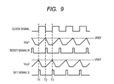
- FIG. 9 is a timing chart indicating the operation of the oscillation circuit 30 a.
- the operation of the oscillation circuit 30 a performed during a period for which the clock signal CLK at the low level.
- the capacitive drive circuit 32 the PMOS transistor P 5 is turned off and the NMOS transistor N 2 is turned on. Then the capacitive drive circuit 32 extracts electric charges from the capacitor C 1 by the NMOS transistor N 2 and lower the voltage level of the voltage Vcp 1 .
- the comparator 33 switches the reset signal R from the high level to the low level.
- the capacitive drive circuit 34 During a period for which the clock signal CLK is at the low level, in the capacitive drive circuit 34 , the PMOS transistor P 4 is turned on and the NMOS transistor N 1 is turned off. Then the capacitive drive circuit 34 supplies the output current Iout to the capacitor C 2 through the PMOS transistor P 4 to increase the amount of electric charges accumulated in the capacitor C 2 . It thereby increases the voltage level of the voltage Vcp 2 . When the voltage level of the voltage Vcp 2 thereafter reaches the oscillation reference voltage VREF, the comparator 35 switches the set signal S from the low level to the high level (times T 1 , T 3 ).
- the capacitive drive circuit 34 During a period for which the clock signal CLK is at the high level, in the capacitive drive circuit 34 , the PMOS transistor P 4 is turned off and the NMOS transistor N 1 is turned on. Then the capacitive drive circuit 34 extracts electric charges from the capacitor C 2 by the NMOS transistor N 1 and lower the voltage level of the voltage Vcp 2 .
- the comparator 35 switches the set signal S from the high level to the low level.
- the SR latch circuit 36 switches the clock signal between the high level and the low level in response to a rising edge of the set signal S and a rising edge of the reset signal R.
- the speed (dV/dt) of rise in the voltages Vcp 1 , Vcp 2 can be expressed as a function of the output current Iout. This function is shown as Expression (3).
- C is the capacitance value of the capacitors C 1 , C 2 .
- the oscillating frequency is determined by the time it takes for the voltages Vcp 1 , Vcp 2 to reach the oscillation reference voltage VREF from the ground voltage level.
- Expression (3) when the capacitance value of the capacitors C 1 , C 2 is constant, the rising speed of the voltages Vcp 1 , Vcp 2 is determined by the magnitude of the output current Iout. That is, the frequency of the clock signal outputted by the oscillation circuit 30 a is determined by the current value of the output current Iout.
- the coefficient of variation with temperature variation can be set to zero. That is, the oscillation circuit 30 a in FIG. 8 whose oscillating frequency is determined based on the output current Iout outputted by the constant current generation circuit 1 makes it possible to achieve high frequency accuracy (for example, variation width of less than 1%).
- FIG. 10 is a block diagram illustrating an oscillation circuit 30 b as another example of the oscillation circuit 30 .
- the oscillation circuit 30 b includes a frequency detection circuit 40 , a differential amplifier 42 , an oscillator 44 (for example, voltage controlled oscillator), a control circuit 45 , and a filter capacitor Cpump.
- the frequency detection circuit 40 generates a frequency detection voltage Vcap whose voltage level varies according to the length of the period of the clock signal CLK based on a timing control signal outputted by the control circuit 45 .
- the timing control signal includes a charge reset signal INIT, a ramp control signal RAMP, and a hold control signal HOLD.
- the frequency detection circuit 40 generates the frequency detection voltage Vcap according to these signals.
- the frequency detection circuit 40 includes a ramp and hold circuit 41 and a frequency setting capacitor C.
- the output current Iout is inputted from the constant current generation circuit 1 . That is, at the ramp and hold circuit 41 , the current value of charging/discharging current is set by the output current Iout.
- the ramp and hold circuit 41 supplies a charging/discharging current to the frequency setting capacitor C and resets the electric charges accumulated in the frequency setting capacitor C based on the timing control signal.
- the ramp and hold circuit 41 includes an NMOS transistor N 3 and PMOS transistors P 6 , P 7 .
- the PMOS transistors P 6 , P 7 form a differential pair. That is, the PMOS transistors P 6 , P 7 have their sources coupled in common. The source (common junction point) of the PMOS transistors P 6 , P 7 is supplied with the output current Iout.
- the ramp control signal RAMP is inputted to the gate of the PMOS transistor P 6 and the hold control signal HOLD is inputted to the gate of the PMOS transistor P 7 .
- the drain of the PMOS transistor P 6 is coupled with the drain of the NMOS transistor N 3 and provides an output terminal of the ramp and hold circuit 41 .
- the drain of the PMOS transistor P 7 is coupled to a ground terminal.
- the charge reset signal INIT is inputted to the gate of the NMOS transistor N 3 .
- the source of the NMOS transistor N 3 is coupled to a ground terminal.
- the frequency setting capacitor C is coupled between the output terminal of the ramp and hold circuit 41 and a ground terminal.
- the frequency setting capacitor C generates a frequency detection voltage Vcap according to the amount of electric charges accumulated therein.
- the frequency detection voltage Vcap is generated at the node that is the output terminal of the ramp and hold circuit 41 .
- the ramp and hold circuit 41 When the charge reset signal INIT is brought into an enable state (for example, high level), the ramp and hold circuit 41 turns on the NMOS transistor N 3 . The ramp and hold circuit 41 discharges electric charges accumulated in the frequency setting capacitor C and thereby resets the electric charges accumulated in the frequency setting capacitor.
- the charge reset signal INIT is brought into a disenable state (for example, low level) and the ramp control signal RAMP is brought into an enable state (for example, low level)
- the ramp and hold circuit 41 carries out the following processing: it turns off the NMOS transistor N 3 and on the PMOS transistor P 6 . As a result, the ramp and hold circuit 41 accumulates electric charges in the frequency setting capacitor C by a charging/discharging current.
- the ramp and hold circuit 41 carries out the following processing: it turns off the PMOS transistor P 6 and on the PMOS transistor P 7 . As a result, the ramp and hold circuit 41 stops charging of the frequency setting capacitor C and maintains the frequency detection voltage Vcap produced by the electric charges accumulated in the frequency setting capacitor C.
- the differential amplifier 42 continuously varies an oscillating frequency setting current Icp according to the voltage difference between the frequency detection voltage Vcap and the oscillation reference voltage VREF and outputs it to the filter capacitor Cpump. More specific description will be given.
- the differential amplifier 42 includes an amplification unit 43 and a switch circuit SW.
- the frequency detection voltage Vcap is inputted to the inverting input terminal of the amplification unit 43 and the oscillation reference voltage VREF is inputted to the non-inverting input terminal thereof.
- the amplification unit 43 is, for example, a transconductance amplifier and outputs the oscillating frequency setting current Icp having a current value corresponding to the voltage difference between the frequency detection voltage Vcap and the oscillation reference voltage VREF.
- the voltage at the non-inverting input terminal of the amplifier 21 in the constant current generation circuit 1 is used for the oscillation reference voltage VREF.
- the voltage at the non-inverting input terminal of the amplifier 21 is substantially identical with the reference voltage Vconst. However, when the amplifier 21 has an input offset, a voltage difference is produced between the reference voltage Vconst and the voltage at the non-inverting input terminal of the amplifier 21 .
- the voltage at the non-inverting input terminal of the amplifier 21 is a voltage on which the second variation voltage is based. That is, the voltage at the non-inverting input terminal of the amplifier 21 has higher correlation between it and the output current Iout of the constant current generation circuit 1 than between it and the reference voltage Vconst.
- the oscillating frequency of the oscillation circuit 30 b is determined according to the amount of the output current Iout of the constant current generation circuit 1 . Because of the foregoing, the oscillation circuit 30 b can reduce an error of the oscillating frequency from an expected value by operating the oscillation circuit 30 b based on the oscillation reference voltage VREF.
- the switch circuit SW is provided between the output terminal of the amplification unit 43 and the filter capacitor Cpump and its state of conduction is switched according to a pump control signal PULSE included in the timing control signal. More specifically, the switch circuit SW is brought into conduction when the pump control signal PULSE is in an enable state (for example, high level) and out of conduction when the signal is in a disenable state (for example, low level).
- a pump control signal PULSE included in the timing control signal. More specifically, the switch circuit SW is brought into conduction when the pump control signal PULSE is in an enable state (for example, high level) and out of conduction when the signal is in a disenable state (for example, low level).
- the oscillator 44 controls the oscillating frequency of the clock signal CLK according to the voltage level of an oscillating frequency control voltage Vcp.
- the control circuit 45 generates a timing control signal whose logical level is switched based on the period of the clock signal CLK.
- This timing control signal includes a charge reset signal INIT, a ramp control signal RAMP, a hold control signal HOLD, and a pump control signal PULSE.
- the control circuit 45 generates a frequency divided signal obtained by dividing the frequency of the clock signal CLK and switches the logical level of each of the above control signals based on a count value obtained by counting the ticking of the clock of the frequency divided signal. Detailed description will be given later to the timing of switching the logical level of the timing control signal.
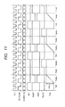
- FIG. 11 is a timing chart indicating the operation of the frequency detection circuit 40 and the control circuit 45 . Description will be given to the timing of switching the logical level of the timing control signal generated by the control circuit 45 switches and the operation of the frequency detection circuit 40 with reference to FIG. 11 .
- the control circuit 45 divides the frequency of the clock signal CLK to generate the frequency divided signal FD.
- the frequency divided signal FD is generated by dividing the frequency of the clock signal CLK into two.
- the control circuit 45 counts the ticking of the clock of the frequency divided signal FD to generate a count value COUNT.
- the count value COUNT is a two-bit value and takes 0 to 3.
- the control circuit 45 switches the logical level of the timing control signal according to the count value COUNT.
- the control circuit 45 carries out the following processing: it brings the charge reset signal INIT to the high level (enable state); it brings the ramp control signal RAMP to the high level (disenable state); it brings the hold control signal HOLD to the low level (enable state); and it brings the pump control signal PULSE to the low level (disenable state).
- a period during which the count value is 0 will be hereafter referred to as charge reset period Tinit.
- the control circuit 45 carries out the following processing: it brings the charge reset signal INIT to the low level (disenable state); it brings the ramp control signal RAMP to the low level (enable state); it brings the hold control signal HOLD to the high level (disenable state); and it brings the pump control signal PULSE to the low level (disenable state).
- a period during which the count value is 1 will be hereafter referred to as ramp period Tramp.
- the control circuit 45 carries out the following processing: it brings the charge reset signal INIT to the low level (disenable state); it brings the ramp control signal RAMP to the high level (disenable state); it brings the hold control signal HOLD to the low level (enable state); and it brings the pump control signal PULSE to the low level (disenable state).
- a period during which the count value is 2 will be hereafter referred to as hold period Thold.
- the control circuit 45 carries out the following processing: it brings the charge reset signal INIT to the low level (disenable state); it brings the ramp control signal RAMP to the high level (disenable state); it brings the hold control signal HOLD to the low level (enable state); and it brings the pump control signal PULSE to the high level (enable state).
- a period during which the count value is 3 will be hereafter referred to as pump period Tpump.
- the frequency detection circuit 40 brings the NMOS transistor N 3 into conduction based on the charge reset signal INIT during a charge reset period Tinit. It thereby resets the electric charges accumulated in the frequency setting capacitor C to a charge amount corresponding to the ground voltage. As a result, the frequency detection voltage Vcap becomes a voltage substantially equal to the ground voltage. At this time, the PMOS transistor P 6 is turned off according to the ramp control signal RAMP and the PMOS transistor P 7 is turned on according to the hold control signal HOLD.
- the frequency detection circuit 40 carries out the following processing: it turns off the NMOS transistor N 3 according to the charge reset signal INIT; it turns on the PMOS transistor P 6 according to the ramp control signal RAMP; and it turns off the PMOS transistor P 7 according to the hold control signal HOLD. That is, during a ramp period Tramp, the frequency detection circuit 40 charges the frequency setting capacitor C with electric charges based on a charging/discharging current. As a result, the voltage level of the frequency detection voltage Vcap is gradually increased. The gradient at which the frequency detection voltage Vcap is increased is determined by the magnitude of the charging/discharging current and the capacitance value of the frequency setting capacitor C.
- the voltage level of the frequency detection voltage Vcap is increased but the voltage drop speed is constant.
- the voltage drop amount dVcap of the frequency detection voltage Vcap during a ramp period Tramp is determined by the length of the ramp period Tramp (the oscillating frequency of the clock signal CLK).
- the frequency detection circuit 40 carries out the following processing: it turns off the NMOS transistor N 3 according to the charge reset signal INIT; it turns off the PMOS transistor P 6 according to the ramp control signal RAMP; and it turns on the PMOS transistor P 7 according to the hold control signal HOLD. That is, the frequency detection circuit 40 carries out the following processing during a hold period Thold: it brings the node to which the frequency setting capacitor C is coupled into a high impedance state and maintains the voltage level of the frequency detection voltage Vcap generated by the frequency setting capacitor C.
- the oscillating frequency setting current Icp is supplied from the differential amplifier 42 to the filter capacitor Cpump.
- the charge reset signal INIT, ramp control signal RAMP, and hold control signal HOLD supplied to the frequency detection circuit 40 are at identical levels between during a hold period Thold and during a pump period Tpump. For this reason, during a pump period Tpump, the voltage level of the frequency detection voltage Vcap is not caused to fluctuate by the frequency detection circuit 40 .
- FIG. 12 is a timing chart indicating the operation of the oscillation circuit 30 b illustrated in FIG. 10 .
- the timing chart in FIG. 12 shows only fluctuation in the frequency detection voltage Vcap, oscillating frequency control voltage Vcp, and clock signal CLK.
- FIG. 12 is based on the assumption that the operation of the oscillation circuit 30 b is started at the origin of the time axis (horizontal axis).
- the oscillation circuit 30 b increases the oscillating frequency control voltage Vcp during each of periods TM 1 to TM 7 .
- Each of the periods TM 1 to TM 7 includes a set of the charge reset period Tinit, ramp period Tramp, hold period Thold, and pump period Tpump shown in FIG. 11 . Since the frequency of the clock signal CLK is increased during each period, the period TM 1 to the period TM 7 are gradually shortened. This is because the timing control signal is generated based on the period of the clock signal CLK.
- the periods TM 11 to TM 17 shown in FIG. 12 correspond to pump periods Tpump.
- the high level-side voltage of the frequency detection voltage Vcap becomes substantially equal to the oscillation reference voltage VREF.
- the oscillating frequency setting current Icp outputted by the differential amplifier 42 is substantially zeroed.
- the frequency detection voltage Vcap is kept at a constant voltage, the oscillating frequency of the clock signal CLK is also kept constant. That is, at the oscillation circuit 30 b, jitter does not occur in the clock signal CLK after the oscillating frequency of the clock signal CLK reaches a target value.
- the filter capacitor Cpump generates the oscillating frequency control voltage Vcp according to the oscillating frequency setting current Icp.
- the differential amplifier 42 outputs the oscillating frequency setting current Icp whose value continuously varies according to the voltage difference between the frequency detection voltage Vcap and the oscillation reference voltage VREF. More specific description will be given.
- the oscillating frequency setting current Icp has a magnitude corresponding to the voltage difference.
- the oscillating frequency setting current Icp is substantially zeroed.
- the following does not take place when the frequency of the clock signal CLK agrees with a target value (for example, when the frequency detection voltage Vcap agrees with the oscillation reference voltage VREF): the oscillating frequency control voltage Vcp does not fluctuate even when the pump control signal PULSE is brought into an enable state.
- the voltage value of the oscillating frequency control voltage Vcp does not fluctuate after the oscillating frequency of the clock signal CLK agrees with a target value.
- the oscillating frequency of the clock signal CLK determined by the oscillator 44 according to the voltage value of the oscillating frequency control voltage Vcp does not differ, either. That is, in the oscillation circuit 30 b, jitter of the clock signal CLK can be reduced.
- the differential amplifier 43 has the switch circuit SW.
- This switch circuit SW is controlled into the open state during the other periods than a period for which the result of input signal difference voltage amplification by the differential amplifier 42 is reflected (for example, a pump period Tpump).
- the frequency detection voltage Vcap takes a voltage value different from a voltage in which the clock signal CLK is reflected during a charge reset period Tinit and a ramp period Tramp.
- the switch circuit SW is controlled into the open state during the other periods than a pump period, it is possible to prevent the following: deviation in the frequency detection voltage Vcap during a charge reset period Tinit and a ramp period Tramp can be prevented from being reflected in an oscillating frequency.
- the oscillating frequency can be stabilized during any period.
- An oscillating frequency is set on the oscillation circuit 30 b based on the output current Iout outputted by the constant current generation circuit 1 . For this reason, the following can be implemented when the coefficient of variation with temperature change of the output current Iout outputted by the constant current generation circuit 1 is substantially zero: the coefficient of variation with temperature variation of the oscillating frequency of the oscillation circuit 30 b can also be substantially zeroed.
- the current value of the output current Iout can be accurately set by trimming the current setting resistor Ri.
- the set value of the oscillating frequency of the clock signal CLK can be set with accuracy (for example, variation width of less than 1%) by taking the following measure: the accuracy of setting the current value of the output current Iout outputted by the constant current generation circuit 1 is enhanced.
- the coefficient of variation with temperature variation and frequency of the clock signal CLK can be accurately set by taking the following measure: the output current Iout outputted by the constant current generation circuit 1 is used to set the frequency of the clock signal CLK.
- the coefficient of variation with temperature variation and frequency of the clock signal CLK can be nestled within a range of deviation of 1% or so. The microprocessor 2 can operate based on such a highly accurate clock signal.
- FIG. 13 is a flowchart illustrating a procedure for start processing for the microprocessor 2 in the second embodiment.
- the decoder 23 selects any one switch based on a gradient set value stored beforehand in the memory 24 in the gradient control unit 22 (Step S 10 ).
- the constant current generation circuit 1 starts operation and outputs the output current lout.
- the oscillation circuit 30 generates the clock signal CLK based on the output current Iout.
- the gradient set value set at the time of startup should be such a value that the output current Iout is minimized. The reason for this is as described below.
- various voltages and circuits are in an unstable state in the initial stage after start. The possibility that trouble occurs in circuit operation is reduced by performing operation according to the clock signal CLK whose frequency is lower than that of the clock signal CLK generated in normal state.
- the computing core PE reads a gradient set value utilized in normal state from the flash memory MEM and supplies the read gradient set value to the memory 24 of the gradient control unit 22 (Step S 12 ).
- the decoder 23 selects any one switch based on the updated gradient set value (Step S 13 ).
- the constant current generation circuit 1 generates the output current Iout utilized in normal state.
- the oscillation circuit 30 changes the frequency of the clock signal CLK to a frequency for normal state based on the output current Iout in normal state (Step S 14 ).
- the generation of the output current Iout and the generation of the clock signal CLK are carried out based on a preset gradient set value for startup.
- the generation of the output current Iout and the generation of the clock signal CLK are carried out based on a gradient set value utilized in normal state.
- Adoption of this starting procedure obviates the necessity for providing a means for storing a gradient set value utilized in normal state in the memory 24 in the constant current generation circuit 1 . This is because gradient set values utilized in normal state can be stored in such a nonvolatile memory as a flash memory in which values can be relatively easily rewritten.
- the gradient set value used in start processing may be a value determined without taking temperature variation in the output current Iout or the like into account and can be set in a circuit design stage.
- FIG. 14 is a circuit diagram of the delay circuit 50 .
- the delay circuit 50 includes NMOS transistors N 10 to N 14 , PMOS transistors P 10 to P 13 , and a capacitor Cd.
- the NMOS transistor N 10 has its source coupled to a ground terminal and has its drain and gate coupled together.
- the drain of the NMOS transistor N 10 has the output current Iout of the constant current generation circuit 1 inputted thereto. This output current Iout will be hereafter referred to as current I 1 .
- the NMOS transistors N 11 , N 12 form a current mirror circuit together with the NMOS transistor N 10 .
- the PMOS transistor P 10 has its source coupled to a ground terminal and has its drain and gate coupled together.
- the drain of the PMOS transistor P 10 is coupled with the drain of the NMOS transistor N 11 .
- the drain of the PMOS transistor P 10 has a current I 2 flowing to the NMOS transistor N 11 inputted thereto. This current I 2 is generated by a current mirror comprised of the NMOS transistors N 10 , N 11 based on the current I 1 .
- the PMOS transistor P 11 forms a current mirror circuit together with the PMOS transistor P 10 .
- the source of the NMOS transistor N 13 is coupled to the drain of the NMOS transistor N 12 .
- the drain of the NMOS transistor N 13 is coupled to the drain of the PMOS transistor P 12 .
- the source of the PMOS transistor P 12 is coupled to the drain of the PMOS transistor P 11 .
- the gate of the NMOS transistor N 12 and the gate of the PMOS transistor P 12 are coupled to each other and these gates are supplied with an input signal Vin.
- the point of junction between the drain of the PMOS transistor P 12 and the drain of the NMOS transistor N 13 provides an intermediate output node (a node at which an intermediate voltage Vc is generated).
- a current 14 generated by a current mirror circuit comprised of the NMOS transistors N 10 , N 12 based on the current I 1 is passed.
- a current 13 generated by a current mirror circuit comprised of the PMOS transistors N 10 , N 11 based on the current I 2 is passed.
- the capacitor Cd is coupled between the intermediate output node and a ground terminal.
- the source of the NMOS transistor N 14 is coupled to a ground terminal.
- the drain of the NMOS transistor N 14 is coupled to the drain of the PMOS transistor P 13 .
- the source of the PMOS transistor P 13 is coupled to a power supply terminal.
- the gate of the NMOS transistor N 14 and the gate of the PMOS transistor P 13 are coupled to each other and the intermediate output node is coupled to these gates.
- the point of junction between the drain of the PMOS transistor P 12 and the drain of the NMOS transistor N 13 is an output terminal of the delay circuit 50 and an output signal Vout is outputted therefrom. That is, the NMOS transistor N 14 and the PMOS transistor P 13 form an output inverter of the delay circuit 50 .
- FIG. 15 is a timing chart indicating the operation of the delay circuit 50 .
- the NMOS transistor N 13 is turned off and the PMOS transistor P 12 is turned on during a period for which the input signal Vin is at the low level.
- electric charges are accumulated in the capacitor Cd by the current 13 passed by way of the PMOS transistor P 12 .
- the intermediate voltage Vc is gradually increased.
- the output signal Vout falls.
- the NMOS transistor N 13 is turned on and the PMOS transistor P 12 is turned off during a period for which the input signal Vin is at the high level. Then electric charges accumulated in the capacitor Cd are discharged by the current 14 passed by way of the NMOS transistor N 13 . As a result, the intermediate voltage Vc is gradually reduced. When the intermediate voltage Vc thereafter becomes lower than the threshold voltage Vth of the output inverter, the output signal Vout rises.
- charging of the capacitor Cd is carried out by the current 13 and discharging of the capacitor Cd is carried out by the current 14 .
- These currents 13 , 14 are both generated by a current mirror circuit based on the current I 1 .
- the delay time Td is defined as follows: the time from a rising edge or a falling edge of the input signal Vin to when the intermediate voltage Vc gets across the threshold voltage Vth of the output inverter. That is, in the delay circuit 50 , the delay time Td can be kept constant regardless of the temperature when the coefficient of variation with temperature variation of the output current Iout (current I 1 ) is substantially zero. In the delay circuit 50 , an accurate delay time Td can be set when the current value of the output current Iout is accurately set. This delay circuit 50 may be incorporated in the microprocessor 2 in the second embodiment.
- the delay circuit 50 When the delay circuit 50 is incorporated in the microprocessor 2 , the circuit can be operated by the start processing illustrated in FIG. 13 .
- FIG. 16 is a circuit diagram of the output circuit 60 .
- the output circuit 60 includes an inverter 61 and NMOS transistors N 20 to N 24 .
- the output circuit 60 drives a load device 62 coupled between an output terminal Tout and a power supply terminal with a driving current.
- the NMOS transistor N 20 has the output current lout outputted by the constant current generation circuit 1 inputted to the drain thereof.
- the source of the NMOS transistor N 20 is coupled to the drain of the NMOS transistor N 21 .
- the gate of the NMOS transistor N 20 has an enable signal EN inputted thereto.
- the drain of the NMOS transistor N 21 is coupled with the gate of the NMOS transistor N 21 .
- the source of the NMOS transistor N 21 is coupled to a ground terminal.
- the NMOS transistor N 22 forms a current mirror circuit together with the NMOS transistor N 21 .
- the drain of the NMOS transistor N 22 is coupled to the output terminal Tout.
- the gate of the NMOS transistor N 24 has an inversion signal of the enable signal EN inputted thereto through the inverter 61 .
- the source of the NMOS transistor N 24 is coupled to a ground terminal.
- the drain of the NMOS transistor N 24 is coupled to the gate of the NMOS transistor N 21 .
- the NMOS transistor N 20 is turned on and the NMOS transistor N 24 is turned off when the enable signal EN is in an enable state (for example, high level).
- the output current Iout flows as a current I 10 to the NMOS transistor N 21 .
- a current I 11 is generated based on the current I 10 by a current mirror circuit comprised of the NMOS transistors N 21 , N 22 . This current I 11 becomes a driving current supplied to the load device 62 .
- the NMOS transistor N 20 is turned off and the NMOS transistor N 24 is turned on when the enable signal EN is in a disenable state (for example, low level).
- the output current Iout is blocked at the NMOS transistor N 20 .
- the NMOS transistor N 24 is on, the gates of the NMOS transistors N 21 , N 22 are brought to ground voltage and a current mirror circuit comprised of the NMOS transistors N 21 , N 22 is brought into a stopped state. That is, the current I 11 does not flow.
- the driving current for driving the load device 62 is determined according to the output current lout outputted by the constant current generation circuit 1 .
- the output circuit 60 can keep the driving current constant regardless of temperature variation when the coefficient of variation with temperature variation of the output current Iout is zero.
- the output circuit 60 can keep the amplitude of voltage generated across the load device 62 constant regardless of temperature variation.
- the amplitude of voltage generated across the load device 62 can be accurately set by the constant current generation circuit 1 accurately setting the current value of the output current Iout and outputting it.
Landscapes
- Engineering & Computer Science (AREA)
- Physics & Mathematics (AREA)
- Microelectronics & Electronic Packaging (AREA)
- Electromagnetism (AREA)
- General Physics & Mathematics (AREA)
- Radar, Positioning & Navigation (AREA)
- Automation & Control Theory (AREA)
- Nonlinear Science (AREA)
- Control Of Electrical Variables (AREA)
- Semiconductor Integrated Circuits (AREA)
- Continuous-Control Power Sources That Use Transistors (AREA)
- Amplifiers (AREA)
Abstract
Description
- The disclosure of Japanese Patent Application No. 2011-78152 filed on Mar. 31, 2011 including the specification, drawings and abstract is incorporated herein by reference in its entirety.
- The present invention relates to constant current generation circuits and microprocessors including them and in particular to a constant current generation circuit that outputs a current having a stable current value against variation of temperature and a microprocessor including it.
- In the circuits of semiconductor devices, a constant current generation circuit that generates a constant current for setting the operating current of a circuit or the operating characteristics of a circuit is frequently utilized. (The examples of the operating characteristics include the oscillating frequency of an oscillation circuit, the delay time of a delay circuit, and the like.) Constant current generation circuits may be required to maintain a constant current value regardless of the temperature of a semiconductor substrate. This is because temperature variation in the operating characteristics of a circuit due to the temperature of a semiconductor substrate can be suppressed by taking the following measure: variation in output current (temperature variation in output current) due to the temperature of the semiconductor substrate is suppressed.
- A technology for suppressing variation in output current due to the temperature of a semiconductor substrate as mentioned above is described in
Patent Document 1.FIG. 17 is a block diagram of the RC oscillator described inPatent Document 1. In theRC oscillator 100 illustrated inFIG. 17 , abias circuit portion 101 outputs current IRAMP based on the resistance value of a resistor R. A ramp/hold circuit portion 102 generates voltage VHOLD having a gradient in proportion to the magnitude of current IRAMP. - In the
RC oscillator 100, resistors Ra, Rb are coupled in series to form the resistor R. The resistance value of the resistor Ra is reduced as the temperature rises and the resistance value of the resistor Rb is increased as the temperature rises. That is, in theRC oscillator 100, the resistor R is configured by combining two resistors having such characteristics that their resistance values oppositely fluctuate with temperature; and fluctuation in the resistance value of the resistor R with temperature is thereby suppressed. In theRC oscillator 100, temperature variation in the current value of current IRAMP generated based on the resistance value of the resistor R is thereby suppressed. - A method in which temperature variation in the resistance value of an entire resistor is suppressed by combining two resistors having opposite fluctuation characteristics with temperature is also disclosed in
Patent Documents 2 and 3. - Japanese Patent No. 4460588
- Japanese Patent Application Publication No. 2005-286021
- Japanese Patent Application Publication No. 2005-333298
- In general, resistors different in temperature variation are formed in different semiconductor processes. Resistors different in temperature variation have different production tolerances. For this reason, when the resistance value of a combined resistance obtained by combining these resistors varies, it is necessary to trim either resistor to match the combined resistance with an expected value. In a circuit including a combined resistance, however, it is difficult to identify which resistor comprising the combined resistance should be trimmed when trimming is carried out because the circuit characteristics are determined by the resistance value of the entire combined resistance. For example, even though the resistance value of the combined resistance can be set to an expected value by trimming either resistor, the resistance ratio between the two resistors drifts. As a result, a problem of deviation of the temperature characteristic of the resistance value of the combined resistance from the expected value arises.
- That is, in the technology described in
Patent Document 1, it is difficult to trim a resistance value and this poses the following problem: it is impossible to eliminate deviation of the temperature characteristic of current IRAMP based on the respective production tolerances of resistors comprising a combined resistance (resistor R).Patent Documents 2 and 3 also involve a problem that it is impossible to eliminate deviation of circuit characteristics based on the respective production tolerances of resistors comprising a combined resistance. - According to an aspect of the invention, a constant current generation circuit includes: a temperature variable voltage generation unit that generates a first variation voltage whose voltage value fluctuates with temperature; a variation gradient adjustment unit that generates a second variation voltage based on a reference voltage smaller in the amount of variation with temperature than the first variation voltage and the first variation voltage; and a current generation unit that includes a current setting resistor whose resistance value fluctuates with temperature and generates an output current based on the second variation voltage and the current setting resistor. The variation gradient adjustment unit sets the coefficient of variation with temperature of the second variation voltage so that the following is implemented: the difference between it and the coefficient of variation with temperature in the resistance value of the current setting resistor falls within a preset first stipulated range.
- According to another aspect of the invention, a microprocessor includes: a memory in which a program and a set value are stored; a computing core that carries out computation processing based on the program stored in the memory; and a constant current generation circuit. The constant current generation circuit includes: a temperature variable voltage generation unit that generates a first variation voltage whose voltage value fluctuates with temperature; a variation gradient adjustment unit that generates a second variation voltage based on a reference voltage smaller in the amount of variation with temperature than the first variation voltage and the first variation voltage; and a current generation unit that includes a current setting resistor whose resistance value fluctuates with temperature and generates an output current based on the second variation voltage and the current setting resistor. The variation gradient adjustment unit sets the coefficient of variation with temperature of the second variation voltage so that the following is implemented: the different between it and the coefficient of variation with temperature in the resistance value of the current setting resistor falls within a preset first stipulated range.
- In a constant current generation circuit and a microprocessor including it according to the aspects of the invention, the following can be implemented: temperature variation in output current can be suppressed just by a variation gradient adjustment unit adjusting the coefficient of variation (gradient) in second variation voltage. More specific description will be given. In a constant current generation circuit and a microprocessor including it of the invention, there is only one item for adjusting temperature variation in output current. Therefore, increase in temperature variation in output current can be prevented by adjustment processing.
- In a constant current generation circuit and a microprocessor including it according to the aspects of the invention, temperature variation in output current can be adequately improved by adjustment processing.
-
FIG. 1 is a block diagram of a constant current generation circuit in a first embodiment; -
FIG. 2 is a graph indicating differences in temperature variation in a second variation voltage due to different output taps of the variation gradient adjustment unit of a constant current generation circuit in the first embodiment; -
FIG. 3 is a graph indicating temperature variation in the current setting resistor of the current generation unit of a constant current generation circuit in the first embodiment; -
FIG. 4 is a graph indicating differences in temperature variation in an output current due to different voltage output points for a second variation voltage in the variation gradient adjustment unit of a constant current generation circuit in the first embodiment; -
FIG. 5 is a graph indicating differences in temperature variation in an output current according to the presence or absence of a sealing material for a semiconductor chip in which a constant current generation circuit in the first embodiment is formed; -
FIG. 6 is a flowchart illustrating a setting procedure for a set value in a constant current generation circuit in the first embodiment; -
FIG. 7 is a block diagram of a microprocessor in a second embodiment; -
FIG. 8 is a block diagram illustrating an example of an oscillation circuit in the second embodiment; -
FIG. 9 is a timing chart indicating the operation of the oscillation circuit illustrated inFIG. 8 ; -
FIG. 10 is a block diagram illustrating another example of an oscillation circuit in the second embodiment; -
FIG. 11 is a timing chart indicating the operation of the control circuit of the oscillation circuit illustrated in FIG. - 10;
-
FIG. 12 is a timing chart indicating the operation of the oscillation circuit illustrated inFIG. 10 ; -
FIG. 13 is a flowchart illustrating a starting procedure for a microprocessor in the second embodiment; -
FIG. 14 is a circuit diagram of a delay circuit in a third embodiment; -
FIG. 15 is a timing chart indicating the operation of a delay circuit in the third embodiment; -
FIG. 16 is a circuit diagram of an output circuit in the third embodiment; and -
FIG. 17 is a block diagram of an RC oscillation circuit according toPatent Document 1. - Hereafter, description will be given to embodiments of the invention with reference to the drawings.
FIG. 1 is a block diagram of a constantcurrent generation circuit 1 in the first embodiment. As illustrated inFIG. 1 , the constantcurrent generation circuit 1 includes a temperature variablevoltage generation unit 10, a constantvoltage generation unit 11, a variationgradient adjustment unit 12, and acurrent generation unit 13. - The temperature variable
voltage generation unit 10 generates a first variation voltage whose voltage value fluctuates with temperature. In this embodiment, the temperature variablevoltage generation unit 10 includes a diode Di and outputs the forward voltage Vf of the diode Di as first variation voltage. (This voltage will be hereafter referred to as first variation voltage Vf.) The diode has its cathode coupled to a second power supply terminal (for example, ground terminal) and generates the first variation voltage at its anode. The first variation voltage Vf generated by the diode Di is the forward voltage of the diode and has a coefficient of variation of −2 mV/° C. or so (temperature characteristic negative to temperature). The temperature variablevoltage generation unit 10 may generate a first variation voltage having a positive temperature characteristic. The coefficient of variation with temperature of the first variation voltage can be set according to the characteristics of a utilized element or circuit. - The constant
voltage generation unit 11 generates a reference voltage Vconst smaller in the amount of variation with temperature than the first variation voltage. In this embodiment, a band-gap voltage source that generates the reference voltage Vconst based on a band-gap voltage is used for the constantvoltage generation unit 11. This reference voltage Vconst is far smaller in variation with temperature than the first variation voltage and is substantially constant to temperature. The reference voltage Vconst may be generated by a circuit (for example, resistance voltage dividing circuit or the like) other than a band-gap voltage source. The variationgradient adjustment unit 12 generates a second variation voltage Vrefc based on the reference voltage Vconst and the first variation voltage Vf. At this time, the variationgradient adjustment unit 12 sets the following difference within a preset first stipulated range: the difference between the coefficient of variation with temperature of the second variation voltage Vrefc and the coefficient of variation with temperature of the resistance value of the current setting resistor Ri described later. The variationgradient adjustment unit 12 includes at least either of a first gradient voltage generation unit that generates multiple first voltages and a second gradient voltage generation unit that generates multiple second voltages. Each of the first voltages has a gradient of a second temperature characteristic whose gradient is opposite to a first temperature characteristic and they have different coefficients of variation with temperature. Each of the second voltages has a gradient of the first temperature characteristic and they have different coefficients of variation with temperature. In the variationgradient adjustment unit 12, the first variation voltage Vf has a gradient of the first temperature characteristic. When the resistance value of the current setting resistor Ri has a gradient of the second temperature characteristic, the variation gradient adjustment unit takes one voltage selected from among the first voltages as second variation voltage Vrefc. When the first variation voltage Vf and the resistance value of the current setting resistor Ri have a gradient of the first temperature characteristic, the variationgradient adjustment unit 12 takes one voltage selected from among the second voltages as second variation voltage Vrefc. The current setting resistor Ri is a resistor provided in thecurrent generation unit 13 described later. The following description is based on the assumption that: the first temperature characteristic is of a negative gradient (a gradient whose value is reduced with rise in temperature) and the second temperature characteristic is of a positive gradient (a gradient whose value is increased with rise in temperature). Detailed description will be given later to how the variationgradient adjustment unit 12 adjusts the gradient to temperature of the second variation voltage. - The variation
gradient adjustment unit 12 includes anamplifier 21, a first gradient voltage generation unit (first resistor R1), a second gradient voltage generation unit (second resistor R2), a PMOS transistor P1, and agradient control unit 22. Theamplifier 21, first resistor R1, second resistor R2, and PMOS transistor P1 form an inverting amplifier. The inverting input terminal of theamplifier 21 has the reference voltage Vconst inputted thereto; and the non-inverting input terminal thereof has a voltage VO generated at the node between the first resistor R1 and the second resistor R2 inputted thereto. The PMOS transistor P1 has its source coupled to a first power supply terminal (for example, power supply terminal VDD) and its drain coupled to the cathode of the diode Di through the first resistor R1 and the second resistor R2. The gate of the PMOS transistor P1 is supplied with an error voltage generated by theamplifier 21 based on the voltage difference between the reference voltage Vconst and the voltage V0. That is, this inverting amplifier uses the first variation voltage Vf as input voltage and amplifies the first variation voltage Vf with an amplification factor set according to the ratio of the first resistor R1 to the second resistor R2. Thus it generates a voltage obtained by amplifying the first variation voltage Vf at the node between the drain of the PMOS transistor P1 and the first resistor R1. - The first resistor Ri is formed by coupling multiple resistors R11 to R1m (m is an integer not less than 2) in series. The second resistor R2 is formed by coupling multiple resistors R21 to R2 n (n is an integer not less than 2) in series. The first resistor R1 is provided at each point of junction between the resistors with an output tap. The second resistor R2 is provided at each point of junction between the resistors with an output tap. In the example in
FIG. 1 , multiple first voltages (for example, voltages V11 to V1m) are generated at the output taps of the first resistor R1. The voltages V11 to V1m are respectively voltages generated at the high potential-side terminals of the resistors R11 to R1m. The voltage V11 is a voltage obtained by amplifying the first variation voltage Vf with an amplification factor determined according to the resistance ratio of the first resistor R1 to the second resistor R2. In the example illustrated inFIG. 1 , multiple second voltages (for example, voltages V21 to V2n) are generated at the output taps of the second resistor R2. The voltages V21 to V2 n are respectively voltages generated at the low potential-side terminals of the resistors R21 to R2n. The voltage V2 n is a voltage identical with the first variation voltage Vf. In addition, an output tap is provided also between the first resistor R1 and the second resistor R2 and the voltage V0 is generated at this output tap. That is, the voltages V12 to Vim, V0, V21 to V2n−1 have voltage values obtained by dividing the voltage difference between the first variation voltage Vf and the voltage V11 by the resistors R11 to R1 m and the resistors R21 to R2 n. The coefficients of variation with temperature of the voltages V12 to V1m, V0, V21 to V2n−1 differ according to a division ratio determined by the resistors R11 to R1m and the resistors R21 to R2n. Detailed description will be given later to the coefficients of variation with temperature of the voltages V11 to V1m, V0, V21 to V2n. - The
gradient control unit 22 changes the coefficient of variation of the second variation voltage Vrefc based on a gradient set value. More specifically, thegradient control unit 22 changes an output tap for outputting the second variation voltage based on a gradient set value and thereby changes the coefficient of variation of the second variation voltage. Thegradient control unit 22 includes switches SW11 to SW1 m, SW0, SW21 to SW2 n, adecoder 23, and a storage unit (for example, memory) 24. - One ends of the switches SW11 to SW1 m are respectively coupled to the output taps at which the voltages V11 to Vim are generated. One end of the switch SW0 is coupled to the output tap at which the voltage V0 is generated. One ends of the switches SW21 to SW2 n are respectively coupled to the output taps at which the voltages V21 to V2 n are generated. The other ends of the switches SW11 to SW1 m, SW0, SW21 to SW2 n are coupled in common.
- In the
memory 24, a preset gradient set value is stored. This memory may be a nonvolatile memory such as a flash memory, may be a fuse circuit that holds a value by physical disruption of an element or the like, or may be a volatile memory such as DRAM. Thedecoder 23 selects any one of the switches SW11 to SW1 m, SW0, SW21 to SW2 n based on a gradient set value read from thememory 24. That is, thegradient control unit 22 selects one of the voltages generated at the output taps provided at the multiple points of junction between the resistors comprising the first resistor R1 and the second resistor R2 and outputs it as second variation voltage. - The
current generation unit 13 includes anerror amplifier 25, PMOS transistors P2, P3, and the current setting resistor Ri. Thecurrent generation unit 13 generates an output current Iout based on the second variation voltage Vrefc and the current setting resistor Ri. - With respect to the current setting resistor Ri, for example, its resistance value has a positive temperature characteristic to temperature. The PMOS transistor P2 has its source coupled to a power supply terminal and its drain coupled to a ground terminal through the current setting resistor Ri. The
error amplifier 25 supplies an error voltage to the gate of the PMOS transistor P2 based on the voltage difference between a current setting voltage generated at the node between the PMOS transistor P2 and the current setting resistor Ri and the second variation voltage Vrefc. Then the PMOS transistor P2 outputs a current to the current setting resistor so that the voltage generated across the current setting resistor Ri based on the error voltage becomes equal to the second variation voltage Vrefc. In thecurrent generation unit 13, the current setting voltage generated at the node between the drain of the PMOS transistor P2 and the current setting resistor Ri take the same voltage value as the second variation voltage Vrefc by virtual short-circuiting of theerror amplifier 25. - The PMOS transistor P3 is coupled with the PMOS transistor P2 in a current mirror configuration. The PMOS transistor P3 outputs as output current a current in proportion to a current passed through the current setting resistor Ri by the PMOS transistor P2. The ratio of the current passed through the PMOS transistor P2 to the current passed through the PMOS transistor P3 is determined by the transistor size ratio of the two transistors. When the transistor size ratio is 1:1, for example, the current passed through the PMOS transistor P2 and the current passed through the PMOS transistor P3 are identical with each other. When the transistor size ratio is 1:2, the current passed through the PMOS transistor P3 is twice the current passed through the PMOS transistor P2. When the PMOS transistors P2, P3 are identical in gate length, their transistor size ratio is determined by the ratio of gate widths. When PNP transistors are used in place of the PMOS transistors P2, P3, the transistor size is determined by the area ratio of the emitters of the PNP transistors.
- Description will be given to the operation of the constant
current generation circuit 1 in the first embodiment.FIG. 2 is a graph indicating differences in temperature variation in the second variation voltage Vrefc due to different output taps of the variationgradient adjustment unit 12 of the constantcurrent generation circuit 1. In the example illustrated inFIG. 2 , the resistance values of the first resistor R1 and the second resistor R2 are set to an identical resistance value. The number of resistors comprising the first resistor R1 and the number of resistors comprising the second resistor R2 are set to an identical number and the resistance values of the resistors R11 to R1m, R21 to R2 n are all made identical. In this case, as indicated inFIG. 2 , the voltages V11 to Vim, V0, V21 to V2 n are different in gradient to temperature variation according to the ratio of the resistor on the upper side of the node at which the relevant output tap is provided and the resistor therebelow. With respect to the voltages V11 to V1m generated at the resistor R1, the gradients of the temperature characteristic are all positive; and with respect to the voltages V21 to V2 n generated at the resistor R2, the gradients of the temperature characteristic are all negative. The reason for this difference in gradient is as described below., The output taps are provided at the multiple points of junction between the resistors comprising the first resistor R1 and the second resistor R2 that determine the amplification factor of the inverting amplifier. As a result, the coefficient of variation with temperature variation of the first variation voltage is amplified by the ratio of the resistors provided above and below each output tap. -
FIG. 3 is a graph indicating temperature variation in the current setting resistor Ri of thecurrent generation unit 13 of a constantcurrent generation circuit 1 in the first embodiment. As indicated inFIG. 3 , the current setting resistor Ri has a positive temperature characteristic and its resistance value is increased as the temperature rises. - The constant
current generation circuit 1 in the first embodiment selects any one of the voltages shown inFIG. 2 at the variationgradient adjustment unit 12 and outputs it as second variation voltage Vrefc. This second variation voltage can be considered as a voltage obtained by adjusting the rate of change with temperature variation of the first variation voltage. In the constantcurrent generation circuit 1 in the first embodiment, the voltage of an output tap to be outputted as second variation voltage Vrefc is selected based on a gradient set value stored in thememory 24. Then the constantcurrent generation circuit 1 selects a voltage with the same coefficient of variation with temperature variation as that of the current setting resistor Ri as second variation voltage Vrefc according to the gradient set value. Thus the current value of the output current Iout becomes constant regardless of temperature variation. - Description will be given to the principle by which the output current Iout becomes constant. The output current Iout obtained when the transistor size ratio of the PMOS transistors P2, P3 is 1:1 can be expressed by Expression (1). In Expression (1), the current value of an output current is represented by lout; the voltage value of the second variation voltage is represented by Vrefc; the resistance value of the current setting resistor is represented by Ri; the rate of change with temperature variation of the second variation voltage is represented by x; and the coefficient of variation with temperature variation of the current setting resistor is represented by y.
-
Iout=(Vrefc*x)/(Ri*y) (1) - When it is set that x=y, Expression (1) can be transformed into Expression (2).
-
Iout=Vrefc/Ri (2) - The following is understood from Expression (1) and Expression (2): when the coefficient of variation with temperature variation of the second variation voltage Vrefc and that of the current setting resistor Ri are identical with each other, the current value of the output current Iout is not influenced by temperature variation.
-
FIG. 4 is a graph indicating differences in temperature variation in the output current due to different output taps for taking out the second variation voltage in the variation gradient adjustment unit of a constant current generation circuit in the first embodiment. In the example shown inFIG. 4 , it is understood that the output current Iout becomes constant regardless of temperature variation by taking the second variation voltage Vrefc out of the output tap from which the voltage V12 is outputted. This is because the coefficient of variation with temperature variation of the voltage V12 shown inFIG. 2 and the coefficient of variation with temperature variation of the current setting resistor Ri are identical with each other. - Description will be given to a setting method for the output current Iout in a constant
current generation circuit 1 in the first embodiment. It is understood from Expression (2) that in the constantcurrent generation circuit 1, the current value of the output current Iout can be set by changing the value of the current setting resistor Ri. The voltages V11 to V1m, V0, V21 to V2 n of the output taps from which the second variation voltage Vrefc is taken out respectively have different voltage values. For this reason, the current value of the output current Iout may get out of a preset stipulated range depending on the voltage selected as second variation voltage. In such a case, the current value of the output current Iout can be set within the stipulated range by trimming the resistance value of the current setting resistor Ri or carrying out any other like processing. - The following resistors can be used for the current setting resistor Ri: a polysilicon resistor (positive temperature characteristic), an N-well resistor (negative temperature characteristic), or a tungsten resistor (positive temperature characteristic) formed over a semiconductor substrate or a resistor provided as an external component. However, in consideration of the reduction of the number of terminals of a semiconductor device and the stabilization of output current, it is desirable to use a tungsten resistor formed over a semiconductor substrate as the current setting resistor Ri.
- This is because the resistance value of the tungsten resistor is stable even when stress on a semiconductor substrate changes.
FIG. 5 indicates differences in temperature variation in an output current caused by the presence or absence of a sealing material (for example, molding resin) on a semiconductor chip in which a constant current generation circuit in the first embodiment is formed. In the example shown inFIG. 5 , the following rates of change are indicated: the rate of change in output current depending on the presence or absence of molding resin observed when a tungsten resistor is used for the current setting resistor Ri; and the rate of change in output current depending on the presence or absence of molding resin observed when a polysilicon resistor is used for the current setting resistor Ri. In the case of the tungsten resistor, as indicated inFIG. 5 , the error between output current obtained without molding resin and output current obtained with molding resin is less than 0.5%. In the case of the polysilicon resistor, meanwhile, the error between output current obtained without molding resin and output current obtained with molding resin is 2% or so at the maximum. A semiconductor device is formed by sealing a semiconductor chip with molding resin and this molding resin gives stress to the semiconductor chip. That is, it is understood fromFIG. 5 that a tungsten resistor can maintain more stable characteristics against stress on a semiconductor chip than a polysilicon resistor. Stress on a semiconductor chip is varied by change in the temperature of molding resin, warp in a mounting board caused when it is mounted, or the like. Therefore, to obtain more stable output current lout, it is desirable to use a tungsten resistor for the current setting resistor Ri. - Description will be given to a setting method for a gradient set value in a constant
current generation circuit 1 in the first embodiment. In the constantcurrent generation circuit 1, in general, a gradient set value is determined and stored in thememory 24 before use is started. However, a stored gradient set value must be determined in a shipment test conducted prior to shipment.FIG. 6 is a flowchart illustrating a setting procedure for a gradient set value in a shipment test. It will be assumed that before the setting procedure illustrated inFIG. 6 is carried out, the gradient set value is set to an initial value set without exception regardless of temperature variation in the output current Iout. - First, in the setting procedure, as illustrated in
FIG. 6 , the temperature of a semiconductor substrate in which the constantcurrent generation circuit 1 is formed is set to a first temperature (Step S1). The first temperature is a temperature lower than the second temperature described later. Then the current value (first output current measurement value) of the output current Iout of the constantcurrent generation circuit 1 formed over the semiconductor substrate set to the first temperature is acquired (Step S2). - Subsequently, the temperature of the semiconductor substrate is set to a second temperature (Step S3). The second temperature is a temperature higher than the first temperature.
- The current value (second output current measurement value) of the output current Iout of the constant
current generation circuit 1 formed over the semiconductor substrate set to the second temperature is acquired (Step S4). - Subsequently, the difference value between the first output current measurement value and the second output current measurement value is calculated (Step S5). This calculation is carried out with a testing device or the like for testing the semiconductor device including the constant
current generation circuit 1. Subsequently, it is determined whether or not the difference value calculated at Step S5 is within a preset stipulated range (Step S6). Ideally, it is desirable that the coefficient of variation with temperature variation of the output current Iout should be zero. However, since the voltages V11 to V1m, V0, V21 to V2 n generated at the variationgradient adjustment unit 12 take discrete voltage values, it is not realistic to zero the coefficient of variation with temperature variation of the output current Iout. At Step S6, consequently, a stipulated range is stipulated by an upper limit value and a lower limit value and when the difference value is within the stipulated range, it is considered that the requirements are met. - When it is determined at Step S6 that the difference value is out of the stipulated range, the processing of Step S7 is carried out. At Step S7, a switch to be selected by the decoder is determined according to the magnitude of the difference value and the gradient set value is updated with a value corresponding to the determined switch. For example, when the difference value is lower than the lower limit value, the gradient set value is updated with the following value: such a value that a switch corresponding to an output tap at which a higher voltage than the present value is generated according to the amount of deviation of the difference value from the lower limit value. When it is determined at Step S6 that the difference value is within the stipulated range, the series of processing is terminated.
- As described above, in the constant
current generation circuit 1 in the first embodiment, the variationgradient adjustment unit 12 generates the following second variation voltage from the first variation voltage Vf having a predetermined coefficient of variation with temperature variation: the second variation voltage Vrefc having such a coefficient of variation as to agree with the coefficient of variation with temperature variation of the resistance value of the current setting resistor Ri. At the variationgradient adjustment unit 12, at this time, the coefficient of variation with temperature variation of the second variation voltage Vrefc is adjusted by only changing an output tap at which an voltage outputted as second variation voltage is generated. That is, at the constantcurrent generation circuit 1, the coefficient of variation with temperature variation of the second variation voltage Vrefc can be adjusted by only one parameter so that the output current becomes constant regardless of the temperature. - In the technology described in
Patent Document 1, the current IRAMP is generated by the resistance value of the resistor R obtained by combining two resistors whose resistance values oppositely fluctuate with temperature. As indicated inFIG. 3 ofPatent Document 1, however, the coefficient of variation with temperature variation of the resistance value of the resistor R is 2% or so. That is, in the technology described inPatent Document 1, variation with temperature in the current IRAMP is 2% or so. Meanwhile, the constantcurrent generation circuit 1 in the first embodiment is capable of confining the coefficient of variation of the output current Iout to 1% or below by taking the following measure: the coefficient of variation with temperature variation of the resistance value of the current setting resistor Ri and the coefficient of variation with temperature variation of the second variation voltage Vrefc are matched with each other. - In the constant
current generation circuit 1 in the first embodiment, the following measure can be taken when the current value of the output current Iout deviates from a stipulated range: it can be corrected by changing the resistance value of the current setting resistor Ri by trimming or the like. Even when the resistance value of the current setting resistor Ri is changed, this change does not have influence on the voltage value or coefficient of variation of the second variation voltage Vrefc. That is, in the constantcurrent generation circuit 1, the current value of the output current Iout can be adjusted independently of the coefficient of variation with temperature variation of the output current lout. In the constantcurrent generation circuit 1, as a result, it is possible to accurately set the current value and coefficient of variation with temperature variation of the output current Iout. - In the technology described in
Patent Document 1, it is difficult to form both of two resistors of metal resistors in the following cases: cases where the two resistors having opposite temperature characteristics to each other to set the current value of the output current Iout by the combined resistance of the two resistors. That is, in the technologies described inPatent Document 1 and the like, it is difficult to reduce variation in output current Iout against stress applied to the semiconductor chip. Meanwhile, in the constantcurrent generation circuit 1 in the first embodiment, the following can be implemented by using such a metal resistor as a tungsten resistor for the current setting resistor Ri: it is possible to generate the output current Iout that does not vary so much even against stress applied to the semiconductor chip in which the constantcurrent generation circuit 1 is formed. - In the constant
current generation circuit 1 in the first embodiment, both the resistors R1, R2 are provided with output taps so that the following can be implemented: the temperature characteristic of the second variation voltage Vrefc may be a positive temperature characteristic or may be a negative temperature characteristic. When the temperature characteristic of the second variation voltage Vrefc may be either of the temperature characteristics, output taps only have to be provided in either of the resistors R1, R2. -
FIG. 7 is a block diagram of amicroprocessor 2 in the second embodiment. As illustrated inFIG. 7 , themicroprocessor 2 includes a computing core PE, a memory (for example, flash memory MEM), and a clock generation circuit CG. The clock generation circuit CG includes a constantcurrent generation circuit 1 in the first embodiment. The clock generation circuit CG utilizes the highly accurate output current Iout generated at the constantcurrent generation circuit 1 to generate a clock signal CLK that does not fluctuate so much with temperature. In the example illustrated inFIG. 2 , the clock signal CLK outputted by the clock generation circuit CG is supplied to the computing core PE and the flash memory MEM. However, this clock signal CLK may be outputted to an external source. - Detailed description will be given to a
microprocessor 2 in the second embodiment. The constantcurrent generation circuit 1 in the following description is substantially the same as that described in relation to the first embodiment; therefore, the detailed description thereof will be omitted here. - In the flash memory MEM, a program and a set value are stored. The computing core PE carries out computation processing based on the program stored in the flash memory. The clock generation circuit CG generates an output signal (clock signal CLK) whose oscillating frequency is determined based on the output current Iout generated by the constant
current generation circuit 1. The flash memory MEM, computing core PE, and clock generation circuit CG are coupled with one another through an internal bus. - Detailed description will be given to an
oscillation circuit 30.FIG. 8 is a block diagram of anoscillation circuit 30 a as an example of theoscillation circuit 30. Theoscillation circuit 30 a includes an inverter 31,capacitive drive circuits comparators SR latch circuit 36, and capacitors C1, C2. - The
capacitive drive circuit 32 includes an NMOS transistor N2 and a PMOS transistor P5. The source of the NMOS transistor N2 is coupled to a ground terminal and the drain thereof is coupled to the drain of the PMOS transistor P5. The point of junction between the drain of the PMOS transistor P5 and the drain of the NMOS transistor N2 is the output node of thecapacitive drive circuit 32. The output current lout outputted by the constantcurrent generation circuit 1 is inputted to the source of the PMOS transistor P5. The gate of the PMOS transistor P5 and the gate of the NMOS transistor N2 are coupled in common and the clock signal CLK outputted by theoscillation circuit 30 a is inputted thereto through the inverter 31. The inverter 31 outputs a signal obtained by inverting the clock signal CLK to thecapacitive drive circuit 32. - The capacitor C1 is coupled between the output node of the
capacitive drive circuit 32 and a ground terminal. At the output node, a voltage Vcp1 is generated according to the amount of electric charges accumulated in the capacitor C1. - The
comparator 33 has the voltage Vcp1 inputted to its non-inverting input terminal and has an oscillation reference voltage VREF inputted to its inverting input terminal. Thecomparator 33 switches the logical level of a reset signal R according to the magnitude relation between the voltage Vcp1 and the oscillation reference voltage VREF. More specific description will be given. When the voltage Vcp1 is higher than the voltage VREF, thecomparator 33 brings the reset signal R to the low level. When the voltage Vcp1 is lower than the oscillation reference voltage VREF, meanwhile, thecomparator 33 brings the reset signal R to the high level. To stably switch the logical level of the outputted reset signal R, it is desirable that thecomparator 33 should be a hysteresis comparator. Letting the hysteresis width be dh, the hysteresis comparator switches the logical level as follows: when the voltage Vcp1>the oscillation reference voltage VREF, it switches the reset signal R from the low level to the high level; and when the voltage Vcp+dh<the oscillation reference voltage VREF, it switches the reset signal R from the high level to the low level. - The
capacitive drive circuit 34 includes an NMOS transistor N1 and a PMOS transistor P4. The source of the NMOS transistor N1 is coupled to a ground terminal and the drain thereof is coupled with the drain of the PMOS transistor P4. The point of junction between the drain of the PMOS transistor P4 and the drain of the NMOS transistor N1 is the output node of thecapacitive drive circuit 34. The output current lout outputted by the constantcurrent generation circuit 1 is inputted to the source of the PMOS transistor P4. The gate of the PMOS transistor P4 and the gate of the NMOS transistor N1 are coupled in common and the clock signal CLK outputted by theoscillation circuit 30 a is inputted thereto. - The capacitor C2 is coupled between the output node of the
capacitive drive circuit 34 and a ground terminal. At the output node, a voltage Vcp2 is generated according to the amount of electric charges accumulated in the capacitor C2. - The
comparator 35 has the voltage Vcp2 inputted to its non-inverting input terminal and the oscillation reference voltage VREF inputted to its inverting input terminal. Thecomparator 35 switches the logical level of a set signal S according to the magnitude relation between the voltage Vcp2 and the oscillation reference voltage VREF. More specific description will be given. When the voltage Vcp2 is higher than the oscillation reference voltage VREF, thecomparator 35 brings the set signal S to the low level. When the voltage Vcp2 is lower than the oscillation reference voltage VREF, thecomparator 35 brings the set signal S to the high level. To stably switch the logical level of the outputted set signal S, it is desirable that thecomparator 35 should be a hysteresis comparator. Letting the hysteresis width be dh, the hysteresis comparator switches the logical level as follows: when the voltage Vcp2>the oscillation reference voltage VREF, it switches the set signal S from the low level to the high level; and when the voltage Vcp1+dh<the oscillation reference voltage VREF, it switches the set signal S from the high level to the low level. - The
SR latch circuit 36 has the set signal S and the reset signal R inputted thereto and outputs an output signal Q. This output signal Q provides the clock signal CLK. TheSR latch circuit 36 causes the clock signal CLK to rise in response to a rising edge of the set signal S and causes the clock signal CLK to fall in response to a falling edge of the reset signal R. - The
oscillation circuit 30 a has the oscillation reference voltage VREF inputted thereto. The voltage at the non-inverting input terminal of theamplifier 21 of the constantcurrent generation circuit 1 is used for this oscillation reference voltage VREF. The voltage at the non-inverting input terminal of theamplifier 21 is substantially identical with the reference voltage Vconst. However, when theamplifier 21 has an input offset, a voltage difference is produced between the reference voltage Vconst and the voltage at the non-inverting input terminal of theamplifier 21. The voltage at the non-inverting input terminal of theamplifier 21 is a voltage on which the second variation voltage is based. That is, the voltage at the non-inverting input terminal of theamplifier 21 has higher correlation between it and the output current Iout of the constantcurrent generation circuit 1 than between it and the reference voltage Vconst. The oscillating frequency of theoscillation circuit 30 a is determined according to the amount of the output current Iout of the constantcurrent generation circuit 1. Because of the foregoing, theoscillation circuit 30 a can reduce an error of the oscillating frequency from an expected value by operating theoscillation circuit 30 a based on the oscillation reference voltage VREF. -
FIG. 9 is a timing chart indicating the operation of theoscillation circuit 30 a. First, description will be given to the operation of theoscillation circuit 30 a performed during a period for which the clock signal CLK at the low level. During a period for which the clock signal CLK is at the low level, in thecapacitive drive circuit 32, the PMOS transistor P5 is turned off and the NMOS transistor N2 is turned on. Then thecapacitive drive circuit 32 extracts electric charges from the capacitor C1 by the NMOS transistor N2 and lower the voltage level of the voltage Vcp1. When the voltage level of the voltage Vcp1 is thereafter lowered from the oscillation reference voltage VREF and becomes lower than a predetermined voltage (for example, VREF-hysteresis width), thecomparator 33 switches the reset signal R from the high level to the low level. - During a period for which the clock signal CLK is at the low level, in the
capacitive drive circuit 34, the PMOS transistor P4 is turned on and the NMOS transistor N1 is turned off. Then thecapacitive drive circuit 34 supplies the output current Iout to the capacitor C2 through the PMOS transistor P4 to increase the amount of electric charges accumulated in the capacitor C2. It thereby increases the voltage level of the voltage Vcp2. When the voltage level of the voltage Vcp2 thereafter reaches the oscillation reference voltage VREF, thecomparator 35 switches the set signal S from the low level to the high level (times T1, T3). - Description will be given to the operation of the
oscillation circuit 30 a performed during a period for which the clock signal CLK at the high level. During a period for which the clock signal CLK is at the high level, in thecapacitive drive circuit 32, the PMOS transistor P5 is turned on and the NMOS transistor N2 is turned off. Thecapacitive drive circuit 32 supplies the output current Iout to the capacitor C1 through the PMOS transistor P5 to increase the amount of electric charges accumulated in the capacitor C1. It thereby increases the voltage level of the voltage Vcp1. When the voltage level of the voltage Vcp1 thereafter reaches the oscillation reference voltage VREF, thecomparator 33 switches the reset signal R from the low level to the high level (time T2). - During a period for which the clock signal CLK is at the high level, in the
capacitive drive circuit 34, the PMOS transistor P4 is turned off and the NMOS transistor N1 is turned on. Then thecapacitive drive circuit 34 extracts electric charges from the capacitor C2 by the NMOS transistor N1 and lower the voltage level of the voltage Vcp2. When the voltage level of the voltage Vcp2 is thereafter lowered from the oscillation reference voltage VREF and becomes lower than a predetermined voltage (for example, VREF-hysteresis width), thecomparator 35 switches the set signal S from the high level to the low level. - The
SR latch circuit 36 switches the clock signal between the high level and the low level in response to a rising edge of the set signal S and a rising edge of the reset signal R. - In the
oscillation circuit 30 a, the speed (dV/dt) of rise in the voltages Vcp1, Vcp2 can be expressed as a function of the output current Iout. This function is shown as Expression (3). In Expression (3), C is the capacitance value of the capacitors C1, C2. -
dV/dt=Iout/C (3) - In the
oscillation circuit 30 a, the oscillating frequency is determined by the time it takes for the voltages Vcp1, Vcp2 to reach the oscillation reference voltage VREF from the ground voltage level. According to Expression (3), when the capacitance value of the capacitors C1, C2 is constant, the rising speed of the voltages Vcp1, Vcp2 is determined by the magnitude of the output current Iout. That is, the frequency of the clock signal outputted by theoscillation circuit 30 a is determined by the current value of the output current Iout. - With respect to the output current Iout generated by the constant
current generation circuit 1 in the first embodiment, the coefficient of variation with temperature variation can be set to zero. That is, theoscillation circuit 30 a inFIG. 8 whose oscillating frequency is determined based on the output current Iout outputted by the constantcurrent generation circuit 1 makes it possible to achieve high frequency accuracy (for example, variation width of less than 1%). - Description will be given to another example of the
oscillation circuit 30.FIG. 10 is a block diagram illustrating anoscillation circuit 30 b as another example of theoscillation circuit 30. As illustrated inFIG. 10 , theoscillation circuit 30 b includes afrequency detection circuit 40, adifferential amplifier 42, an oscillator 44 (for example, voltage controlled oscillator), acontrol circuit 45, and a filter capacitor Cpump. - The
frequency detection circuit 40 generates a frequency detection voltage Vcap whose voltage level varies according to the length of the period of the clock signal CLK based on a timing control signal outputted by thecontrol circuit 45. The timing control signal includes a charge reset signal INIT, a ramp control signal RAMP, and a hold control signal HOLD. Thefrequency detection circuit 40 generates the frequency detection voltage Vcap according to these signals. - As illustrated in
FIG. 10 , thefrequency detection circuit 40 includes a ramp and holdcircuit 41 and a frequency setting capacitor C. To the ramp and holdcircuit 41, the output current Iout is inputted from the constantcurrent generation circuit 1. That is, at the ramp and holdcircuit 41, the current value of charging/discharging current is set by the output current Iout. - The ramp and hold
circuit 41 supplies a charging/discharging current to the frequency setting capacitor C and resets the electric charges accumulated in the frequency setting capacitor C based on the timing control signal. The ramp and holdcircuit 41 includes an NMOS transistor N3 and PMOS transistors P6, P7. The PMOS transistors P6, P7 form a differential pair. That is, the PMOS transistors P6, P7 have their sources coupled in common. The source (common junction point) of the PMOS transistors P6, P7 is supplied with the output current Iout. The ramp control signal RAMP is inputted to the gate of the PMOS transistor P6 and the hold control signal HOLD is inputted to the gate of the PMOS transistor P7. The drain of the PMOS transistor P6 is coupled with the drain of the NMOS transistor N3 and provides an output terminal of the ramp and holdcircuit 41. The drain of the PMOS transistor P7 is coupled to a ground terminal. The charge reset signal INIT is inputted to the gate of the NMOS transistor N3. The source of the NMOS transistor N3 is coupled to a ground terminal. - The frequency setting capacitor C is coupled between the output terminal of the ramp and hold
circuit 41 and a ground terminal. The frequency setting capacitor C generates a frequency detection voltage Vcap according to the amount of electric charges accumulated therein. The frequency detection voltage Vcap is generated at the node that is the output terminal of the ramp and holdcircuit 41. - When the charge reset signal INIT is brought into an enable state (for example, high level), the ramp and hold
circuit 41 turns on the NMOS transistor N3. The ramp and holdcircuit 41 discharges electric charges accumulated in the frequency setting capacitor C and thereby resets the electric charges accumulated in the frequency setting capacitor. When the charge reset signal INIT is brought into a disenable state (for example, low level) and the ramp control signal RAMP is brought into an enable state (for example, low level), the ramp and holdcircuit 41 carries out the following processing: it turns off the NMOS transistor N3 and on the PMOS transistor P6. As a result, the ramp and holdcircuit 41 accumulates electric charges in the frequency setting capacitor C by a charging/discharging current. When the ramp control signal RAMP is brought into a disenable state (for example, high level) and the hold control signal HOLD is brought into an enable state (for example, low level), the ramp and holdcircuit 41 carries out the following processing: it turns off the PMOS transistor P6 and on the PMOS transistor P7. As a result, the ramp and holdcircuit 41 stops charging of the frequency setting capacitor C and maintains the frequency detection voltage Vcap produced by the electric charges accumulated in the frequency setting capacitor C. - The
differential amplifier 42 continuously varies an oscillating frequency setting current Icp according to the voltage difference between the frequency detection voltage Vcap and the oscillation reference voltage VREF and outputs it to the filter capacitor Cpump. More specific description will be given. Thedifferential amplifier 42 includes anamplification unit 43 and a switch circuit SW. The frequency detection voltage Vcap is inputted to the inverting input terminal of theamplification unit 43 and the oscillation reference voltage VREF is inputted to the non-inverting input terminal thereof. Theamplification unit 43 is, for example, a transconductance amplifier and outputs the oscillating frequency setting current Icp having a current value corresponding to the voltage difference between the frequency detection voltage Vcap and the oscillation reference voltage VREF. - In this embodiment, the voltage at the non-inverting input terminal of the
amplifier 21 in the constantcurrent generation circuit 1 is used for the oscillation reference voltage VREF. The voltage at the non-inverting input terminal of theamplifier 21 is substantially identical with the reference voltage Vconst. However, when theamplifier 21 has an input offset, a voltage difference is produced between the reference voltage Vconst and the voltage at the non-inverting input terminal of theamplifier 21. The voltage at the non-inverting input terminal of theamplifier 21 is a voltage on which the second variation voltage is based. That is, the voltage at the non-inverting input terminal of theamplifier 21 has higher correlation between it and the output current Iout of the constantcurrent generation circuit 1 than between it and the reference voltage Vconst. The oscillating frequency of theoscillation circuit 30 b is determined according to the amount of the output current Iout of the constantcurrent generation circuit 1. Because of the foregoing, theoscillation circuit 30 b can reduce an error of the oscillating frequency from an expected value by operating theoscillation circuit 30 b based on the oscillation reference voltage VREF. - The switch circuit SW is provided between the output terminal of the
amplification unit 43 and the filter capacitor Cpump and its state of conduction is switched according to a pump control signal PULSE included in the timing control signal. More specifically, the switch circuit SW is brought into conduction when the pump control signal PULSE is in an enable state (for example, high level) and out of conduction when the signal is in a disenable state (for example, low level). - The
oscillator 44 controls the oscillating frequency of the clock signal CLK according to the voltage level of an oscillating frequency control voltage Vcp. - The
control circuit 45 generates a timing control signal whose logical level is switched based on the period of the clock signal CLK. This timing control signal includes a charge reset signal INIT, a ramp control signal RAMP, a hold control signal HOLD, and a pump control signal PULSE. Thecontrol circuit 45 generates a frequency divided signal obtained by dividing the frequency of the clock signal CLK and switches the logical level of each of the above control signals based on a count value obtained by counting the ticking of the clock of the frequency divided signal. Detailed description will be given later to the timing of switching the logical level of the timing control signal. -
FIG. 11 is a timing chart indicating the operation of thefrequency detection circuit 40 and thecontrol circuit 45. Description will be given to the timing of switching the logical level of the timing control signal generated by thecontrol circuit 45 switches and the operation of thefrequency detection circuit 40 with reference toFIG. 11 . - As indicated in
FIG. 11 , thecontrol circuit 45 divides the frequency of the clock signal CLK to generate the frequency divided signal FD. In the example shown inFIG. 11 , the frequency divided signal FD is generated by dividing the frequency of the clock signal CLK into two. Thecontrol circuit 45 counts the ticking of the clock of the frequency divided signal FD to generate a count value COUNT. In the example shown inFIG. 11 , the count value COUNT is a two-bit value and takes 0 to 3. Thecontrol circuit 45 switches the logical level of the timing control signal according to the count value COUNT. - Specific description will be given. When the count value is 0, the
control circuit 45 carries out the following processing: it brings the charge reset signal INIT to the high level (enable state); it brings the ramp control signal RAMP to the high level (disenable state); it brings the hold control signal HOLD to the low level (enable state); and it brings the pump control signal PULSE to the low level (disenable state). A period during which the count value is 0 will be hereafter referred to as charge reset period Tinit. - When the count value is 1, the
control circuit 45 carries out the following processing: it brings the charge reset signal INIT to the low level (disenable state); it brings the ramp control signal RAMP to the low level (enable state); it brings the hold control signal HOLD to the high level (disenable state); and it brings the pump control signal PULSE to the low level (disenable state). A period during which the count value is 1 will be hereafter referred to as ramp period Tramp. - When the count value is 2, the
control circuit 45 carries out the following processing: it brings the charge reset signal INIT to the low level (disenable state); it brings the ramp control signal RAMP to the high level (disenable state); it brings the hold control signal HOLD to the low level (enable state); and it brings the pump control signal PULSE to the low level (disenable state). A period during which the count value is 2 will be hereafter referred to as hold period Thold. - When the count value is 3, the
control circuit 45 carries out the following processing: it brings the charge reset signal INIT to the low level (disenable state); it brings the ramp control signal RAMP to the high level (disenable state); it brings the hold control signal HOLD to the low level (enable state); and it brings the pump control signal PULSE to the high level (enable state). A period during which the count value is 3 will be hereafter referred to as pump period Tpump. - Description will be given to the operation of the
frequency detection circuit 40. Thefrequency detection circuit 40 brings the NMOS transistor N3 into conduction based on the charge reset signal INIT during a charge reset period Tinit. It thereby resets the electric charges accumulated in the frequency setting capacitor C to a charge amount corresponding to the ground voltage. As a result, the frequency detection voltage Vcap becomes a voltage substantially equal to the ground voltage. At this time, the PMOS transistor P6 is turned off according to the ramp control signal RAMP and the PMOS transistor P7 is turned on according to the hold control signal HOLD. - During a ramp period Tramp, the
frequency detection circuit 40 carries out the following processing: it turns off the NMOS transistor N3 according to the charge reset signal INIT; it turns on the PMOS transistor P6 according to the ramp control signal RAMP; and it turns off the PMOS transistor P7 according to the hold control signal HOLD. That is, during a ramp period Tramp, thefrequency detection circuit 40 charges the frequency setting capacitor C with electric charges based on a charging/discharging current. As a result, the voltage level of the frequency detection voltage Vcap is gradually increased. The gradient at which the frequency detection voltage Vcap is increased is determined by the magnitude of the charging/discharging current and the capacitance value of the frequency setting capacitor C. For example, the gradient (dVcap/dt) of the frequency detection voltage Vcap is expressed by dVcap/dt=Iout/C. During a ramp period Tramp, the voltage level of the frequency detection voltage Vcap is increased but the voltage drop speed is constant. For this reason, the voltage drop amount dVcap of the frequency detection voltage Vcap during a ramp period Tramp is determined by the length of the ramp period Tramp (the oscillating frequency of the clock signal CLK). - During a hold period Thold, the
frequency detection circuit 40 carries out the following processing: it turns off the NMOS transistor N3 according to the charge reset signal INIT; it turns off the PMOS transistor P6 according to the ramp control signal RAMP; and it turns on the PMOS transistor P7 according to the hold control signal HOLD. That is, thefrequency detection circuit 40 carries out the following processing during a hold period Thold: it brings the node to which the frequency setting capacitor C is coupled into a high impedance state and maintains the voltage level of the frequency detection voltage Vcap generated by the frequency setting capacitor C. - During a pump period Tpump, the oscillating frequency setting current Icp is supplied from the
differential amplifier 42 to the filter capacitor Cpump. The charge reset signal INIT, ramp control signal RAMP, and hold control signal HOLD supplied to thefrequency detection circuit 40 are at identical levels between during a hold period Thold and during a pump period Tpump. For this reason, during a pump period Tpump, the voltage level of the frequency detection voltage Vcap is not caused to fluctuate by thefrequency detection circuit 40. - Description will be given to the operation of the
entire oscillation circuit 30 b illustrated inFIG. 10 .FIG. 12 is a timing chart indicating the operation of theoscillation circuit 30 b illustrated inFIG. 10 . The timing chart inFIG. 12 shows only fluctuation in the frequency detection voltage Vcap, oscillating frequency control voltage Vcp, and clock signal CLK.FIG. 12 is based on the assumption that the operation of theoscillation circuit 30 b is started at the origin of the time axis (horizontal axis). - As shown in
FIG. 12 , theoscillation circuit 30 b increases the oscillating frequency control voltage Vcp during each of periods TM1 to TM7. Each of the periods TM1 to TM7 includes a set of the charge reset period Tinit, ramp period Tramp, hold period Thold, and pump period Tpump shown inFIG. 11 . Since the frequency of the clock signal CLK is increased during each period, the period TM1 to the period TM7 are gradually shortened. This is because the timing control signal is generated based on the period of the clock signal CLK. The periods TM11 to TM17 shown inFIG. 12 correspond to pump periods Tpump. - After the period TM7 passes, the high level-side voltage of the frequency detection voltage Vcap becomes substantially equal to the oscillation reference voltage VREF. As a result, at the
oscillation circuit 30 b, the oscillating frequency setting current Icp outputted by thedifferential amplifier 42 is substantially zeroed. For this reason, after the high level-side voltage of the frequency detection voltage Vcap becomes substantially equal to the oscillation reference voltage VREF, this state is maintained. Since the frequency detection voltage Vcap is kept at a constant voltage, the oscillating frequency of the clock signal CLK is also kept constant. That is, at theoscillation circuit 30 b, jitter does not occur in the clock signal CLK after the oscillating frequency of the clock signal CLK reaches a target value. - According to the above description, in the
oscillation circuit 30 b, the filter capacitor Cpump generates the oscillating frequency control voltage Vcp according to the oscillating frequency setting current Icp. At this time, in theoscillation circuit 30 b, thedifferential amplifier 42 outputs the oscillating frequency setting current Icp whose value continuously varies according to the voltage difference between the frequency detection voltage Vcap and the oscillation reference voltage VREF. More specific description will be given. When there is a voltage difference between the frequency detection voltage Vcap and the oscillation reference voltage VREF, the oscillating frequency setting current Icp has a magnitude corresponding to the voltage difference. When there is not a voltage difference between the frequency detection voltage Vcap and the oscillation reference voltage VREF, the oscillating frequency setting current Icp is substantially zeroed. In theoscillation circuit 30 b, as a result, the following does not take place when the frequency of the clock signal CLK agrees with a target value (for example, when the frequency detection voltage Vcap agrees with the oscillation reference voltage VREF): the oscillating frequency control voltage Vcp does not fluctuate even when the pump control signal PULSE is brought into an enable state. In theoscillation circuit 30 b, consequently, the voltage value of the oscillating frequency control voltage Vcp does not fluctuate after the oscillating frequency of the clock signal CLK agrees with a target value. Further, the oscillating frequency of the clock signal CLK determined by theoscillator 44 according to the voltage value of the oscillating frequency control voltage Vcp does not differ, either. That is, in theoscillation circuit 30 b, jitter of the clock signal CLK can be reduced. - In the
oscillation circuit 30 b, thedifferential amplifier 43 has the switch circuit SW. This switch circuit SW is controlled into the open state during the other periods than a period for which the result of input signal difference voltage amplification by thedifferential amplifier 42 is reflected (for example, a pump period Tpump). In theoscillation circuit 30 b, the frequency detection voltage Vcap takes a voltage value different from a voltage in which the clock signal CLK is reflected during a charge reset period Tinit and a ramp period Tramp. However, since the switch circuit SW is controlled into the open state during the other periods than a pump period, it is possible to prevent the following: deviation in the frequency detection voltage Vcap during a charge reset period Tinit and a ramp period Tramp can be prevented from being reflected in an oscillating frequency. In theoscillation circuit 30 b, as a result, the oscillating frequency can be stabilized during any period. - An oscillating frequency is set on the
oscillation circuit 30 b based on the output current Iout outputted by the constantcurrent generation circuit 1. For this reason, the following can be implemented when the coefficient of variation with temperature change of the output current Iout outputted by the constantcurrent generation circuit 1 is substantially zero: the coefficient of variation with temperature variation of the oscillating frequency of theoscillation circuit 30 b can also be substantially zeroed. In the constantcurrent generation circuit 1, the current value of the output current Iout can be accurately set by trimming the current setting resistor Ri. In theoscillation circuit 30 b, for this reason, the set value of the oscillating frequency of the clock signal CLK can be set with accuracy (for example, variation width of less than 1%) by taking the following measure: the accuracy of setting the current value of the output current Iout outputted by the constantcurrent generation circuit 1 is enhanced. - In the
microprocessor 2 in the second embodiment, according to the above description, the coefficient of variation with temperature variation and frequency of the clock signal CLK can be accurately set by taking the following measure: the output current Iout outputted by the constantcurrent generation circuit 1 is used to set the frequency of the clock signal CLK. In themicroprocessor 2 in the second embodiment, for example, the coefficient of variation with temperature variation and frequency of the clock signal CLK can be nestled within a range of deviation of 1% or so. Themicroprocessor 2 can operate based on such a highly accurate clock signal. - Description will be given to a start sequence for the
microprocessor 2 in the second embodiment.FIG. 13 is a flowchart illustrating a procedure for start processing for themicroprocessor 2 in the second embodiment. - As illustrated in
FIG. 13 , when themicroprocessor 2 starts the start processing, first, thedecoder 23 selects any one switch based on a gradient set value stored beforehand in thememory 24 in the gradient control unit 22 (Step S10). As a result, the constantcurrent generation circuit 1 starts operation and outputs the output current lout. Then theoscillation circuit 30 generates the clock signal CLK based on the output current Iout. At this time, it is desirable that the gradient set value set at the time of startup should be such a value that the output current Iout is minimized. The reason for this is as described below. In themicroprocessor 2, various voltages and circuits are in an unstable state in the initial stage after start. The possibility that trouble occurs in circuit operation is reduced by performing operation according to the clock signal CLK whose frequency is lower than that of the clock signal CLK generated in normal state. - Subsequently, the computing core PE reads a gradient set value utilized in normal state from the flash memory MEM and supplies the read gradient set value to the
memory 24 of the gradient control unit 22 (Step S12). In the constantcurrent generation circuit 1, thedecoder 23 selects any one switch based on the updated gradient set value (Step S13). As a result, the constantcurrent generation circuit 1 generates the output current Iout utilized in normal state. Then theoscillation circuit 30 changes the frequency of the clock signal CLK to a frequency for normal state based on the output current Iout in normal state (Step S14). - In the
microprocessor 2 in the second embodiment, as described above, the generation of the output current Iout and the generation of the clock signal CLK are carried out based on a preset gradient set value for startup. After themicroprocessor 2 starts operation based on the clock signal CLK, the generation of the output current Iout and the generation of the clock signal CLK are carried out based on a gradient set value utilized in normal state. Adoption of this starting procedure obviates the necessity for providing a means for storing a gradient set value utilized in normal state in thememory 24 in the constantcurrent generation circuit 1. This is because gradient set values utilized in normal state can be stored in such a nonvolatile memory as a flash memory in which values can be relatively easily rewritten. The gradient set value used in start processing may be a value determined without taking temperature variation in the output current Iout or the like into account and can be set in a circuit design stage. - In the description of the third embodiment, a delay circuit 50 that delays a signal with a delay amount determined by the current amount of the output current Iout generated by the constant
current generation circuit 1 will be taken as an example.FIG. 14 is a circuit diagram of the delay circuit 50. As illustrated inFIG. 14 , the delay circuit 50 includes NMOS transistors N10 to N14, PMOS transistors P10 to P13, and a capacitor Cd. - The NMOS transistor N10 has its source coupled to a ground terminal and has its drain and gate coupled together. The drain of the NMOS transistor N10 has the output current Iout of the constant
current generation circuit 1 inputted thereto. This output current Iout will be hereafter referred to as current I1. The NMOS transistors N11, N12 form a current mirror circuit together with the NMOS transistor N10. - The PMOS transistor P10 has its source coupled to a ground terminal and has its drain and gate coupled together. The drain of the PMOS transistor P10 is coupled with the drain of the NMOS transistor N11. The drain of the PMOS transistor P10 has a current I2 flowing to the NMOS transistor N11 inputted thereto. This current I2 is generated by a current mirror comprised of the NMOS transistors N10, N11 based on the current I1. The PMOS transistor P11 forms a current mirror circuit together with the PMOS transistor P10.
- The source of the NMOS transistor N13 is coupled to the drain of the NMOS transistor N12. The drain of the NMOS transistor N13 is coupled to the drain of the PMOS transistor P12. The source of the PMOS transistor P12 is coupled to the drain of the PMOS transistor P11. The gate of the NMOS transistor N12 and the gate of the PMOS transistor P12 are coupled to each other and these gates are supplied with an input signal Vin. The point of junction between the drain of the PMOS transistor P12 and the drain of the NMOS transistor N13 provides an intermediate output node (a node at which an intermediate voltage Vc is generated). Through the NMOS transistor N13, a current 14 generated by a current mirror circuit comprised of the NMOS transistors N10, N12 based on the current I1 is passed. Through the PMOS transistor N12, a current 13 generated by a current mirror circuit comprised of the PMOS transistors N10, N11 based on the current I2 is passed.
- The capacitor Cd is coupled between the intermediate output node and a ground terminal. The source of the NMOS transistor N14 is coupled to a ground terminal. The drain of the NMOS transistor N14 is coupled to the drain of the PMOS transistor P13. The source of the PMOS transistor P13 is coupled to a power supply terminal. The gate of the NMOS transistor N14 and the gate of the PMOS transistor P13 are coupled to each other and the intermediate output node is coupled to these gates.
- The point of junction between the drain of the PMOS transistor P12 and the drain of the NMOS transistor N13 is an output terminal of the delay circuit 50 and an output signal Vout is outputted therefrom. That is, the NMOS transistor N14 and the PMOS transistor P13 form an output inverter of the delay circuit 50.
- Description will be given to the operation of the delay circuit 50.
FIG. 15 is a timing chart indicating the operation of the delay circuit 50. In the delay circuit 50, as shown inFIG. 15 , the NMOS transistor N13 is turned off and the PMOS transistor P12 is turned on during a period for which the input signal Vin is at the low level. Then electric charges are accumulated in the capacitor Cd by the current 13 passed by way of the PMOS transistor P12. As a result, the intermediate voltage Vc is gradually increased. When the intermediate voltage Vc thereafter becomes higher than the threshold voltage Vth of the output inverter, the output signal Vout falls. - In the delay circuit 50, the NMOS transistor N13 is turned on and the PMOS transistor P12 is turned off during a period for which the input signal Vin is at the high level. Then electric charges accumulated in the capacitor Cd are discharged by the current 14 passed by way of the NMOS transistor N13. As a result, the intermediate voltage Vc is gradually reduced. When the intermediate voltage Vc thereafter becomes lower than the threshold voltage Vth of the output inverter, the output signal Vout rises.
- In the delay circuit 50, charging of the capacitor Cd is carried out by the current 13 and discharging of the capacitor Cd is carried out by the current 14. These
currents currents - In the delay circuit 50, according to the above description, the delay time Td is defined as follows: the time from a rising edge or a falling edge of the input signal Vin to when the intermediate voltage Vc gets across the threshold voltage Vth of the output inverter. That is, in the delay circuit 50, the delay time Td can be kept constant regardless of the temperature when the coefficient of variation with temperature variation of the output current Iout (current I1) is substantially zero. In the delay circuit 50, an accurate delay time Td can be set when the current value of the output current Iout is accurately set. This delay circuit 50 may be incorporated in the
microprocessor 2 in the second embodiment. - When the delay circuit 50 is incorporated in the
microprocessor 2, the circuit can be operated by the start processing illustrated inFIG. 13 . - In the description of the fourth embodiment, the following output circuit will be taken as an example: an
output circuit 60 in which a driving current to be supplied to a load device is determined according to the current amount of the output current Iout generated by the constantcurrent generation circuit 1.FIG. 16 is a circuit diagram of theoutput circuit 60. As illustrated inFIG. 16 , theoutput circuit 60 includes aninverter 61 and NMOS transistors N20 to N24. Theoutput circuit 60 drives aload device 62 coupled between an output terminal Tout and a power supply terminal with a driving current. - The NMOS transistor N20 has the output current lout outputted by the constant
current generation circuit 1 inputted to the drain thereof. The source of the NMOS transistor N20 is coupled to the drain of the NMOS transistor N21. The gate of the NMOS transistor N20 has an enable signal EN inputted thereto. - The drain of the NMOS transistor N21 is coupled with the gate of the NMOS transistor N21. The source of the NMOS transistor N21 is coupled to a ground terminal. The NMOS transistor N22 forms a current mirror circuit together with the NMOS transistor N21. The drain of the NMOS transistor N22 is coupled to the output terminal Tout.
- The gate of the NMOS transistor N24 has an inversion signal of the enable signal EN inputted thereto through the
inverter 61. The source of the NMOS transistor N24 is coupled to a ground terminal. The drain of the NMOS transistor N24 is coupled to the gate of the NMOS transistor N21. - Description will be given to the operation of the
output circuit 60. In theoutput circuit 60, the NMOS transistor N20 is turned on and the NMOS transistor N24 is turned off when the enable signal EN is in an enable state (for example, high level). As a result, the output current Iout flows as a current I10 to the NMOS transistor N21. A current I11 is generated based on the current I10 by a current mirror circuit comprised of the NMOS transistors N21, N22. This current I11 becomes a driving current supplied to theload device 62. - In the
output circuit 60, meanwhile, the NMOS transistor N20 is turned off and the NMOS transistor N24 is turned on when the enable signal EN is in a disenable state (for example, low level). As a result, the output current Iout is blocked at the NMOS transistor N20. Since the NMOS transistor N24 is on, the gates of the NMOS transistors N21, N22 are brought to ground voltage and a current mirror circuit comprised of the NMOS transistors N21, N22 is brought into a stopped state. That is, the current I11 does not flow. - In the
output circuit 60, according to the above description, the driving current for driving theload device 62 is determined according to the output current lout outputted by the constantcurrent generation circuit 1. For this reason, theoutput circuit 60 can keep the driving current constant regardless of temperature variation when the coefficient of variation with temperature variation of the output current Iout is zero. Further, theoutput circuit 60 can keep the amplitude of voltage generated across theload device 62 constant regardless of temperature variation. In addition, the amplitude of voltage generated across theload device 62 can be accurately set by the constantcurrent generation circuit 1 accurately setting the current value of the output current Iout and outputting it. - The invention is not limited to the above embodiments and can be appropriately modified without departing from the subject matter thereof.
Claims (15)
Priority Applications (1)
| Application Number | Priority Date | Filing Date | Title |
|---|---|---|---|
| US14/693,133 US9746870B2 (en) | 2011-03-31 | 2015-04-22 | Semiconductor device including a constant voltage generation unit |
Applications Claiming Priority (2)
| Application Number | Priority Date | Filing Date | Title |
|---|---|---|---|
| JP2011078152A JP5635935B2 (en) | 2011-03-31 | 2011-03-31 | Constant current generation circuit, microprocessor and semiconductor device including the same |
| JP2011-078152 | 2011-03-31 |
Related Child Applications (1)
| Application Number | Title | Priority Date | Filing Date |
|---|---|---|---|
| US14/693,133 Continuation US9746870B2 (en) | 2011-03-31 | 2015-04-22 | Semiconductor device including a constant voltage generation unit |
Publications (2)
| Publication Number | Publication Date |
|---|---|
| US20120249114A1 true US20120249114A1 (en) | 2012-10-04 |
| US9046910B2 US9046910B2 (en) | 2015-06-02 |
Family
ID=46926350
Family Applications (2)
| Application Number | Title | Priority Date | Filing Date |
|---|---|---|---|
| US13/427,359 Active 2032-06-03 US9046910B2 (en) | 2011-03-31 | 2012-03-22 | Constant current generation circuit and microprocessor including the same |
| US14/693,133 Active 2032-07-25 US9746870B2 (en) | 2011-03-31 | 2015-04-22 | Semiconductor device including a constant voltage generation unit |
Family Applications After (1)
| Application Number | Title | Priority Date | Filing Date |
|---|---|---|---|
| US14/693,133 Active 2032-07-25 US9746870B2 (en) | 2011-03-31 | 2015-04-22 | Semiconductor device including a constant voltage generation unit |
Country Status (3)
| Country | Link |
|---|---|
| US (2) | US9046910B2 (en) |
| JP (1) | JP5635935B2 (en) |
| CN (1) | CN102739240B (en) |
Cited By (21)
| Publication number | Priority date | Publication date | Assignee | Title |
|---|---|---|---|---|
| CN105262457A (en) * | 2015-09-24 | 2016-01-20 | 深圳市芯海科技有限公司 | Bias circuit of RC oscillator capable of on-chip and off-chip frequency modulation |
| US9461623B2 (en) * | 2014-05-15 | 2016-10-04 | Macronix International Co., Ltd. | Method and circuit for temperature dependence reduction of a RC clock circuit |
| US20170147019A1 (en) * | 2015-11-23 | 2017-05-25 | Samsung Electronics Co., Ltd. | Circuit and method for generating reference voltage based on temperature coefficient |
| US20180026541A1 (en) * | 2016-07-21 | 2018-01-25 | Renesas Electronics Corporation | Semiconductor device |
| US9886047B2 (en) * | 2015-05-01 | 2018-02-06 | Rohm Co., Ltd. | Reference voltage generation circuit including resistor arrangements |
| US10128794B2 (en) | 2016-09-29 | 2018-11-13 | Macronix International Co., Ltd. | Feedback compensated oscillator |
| US10168719B2 (en) * | 2017-04-28 | 2019-01-01 | Boe Technology Group Co., Ltd. | Digital low dropout regulator and control method thereof |
| US10185013B2 (en) | 2015-03-24 | 2019-01-22 | Samsung Electronics Co., Ltd. | Magnetic resonance imaging (MRI) apparatus and method of generating MR image |
| US10304530B2 (en) * | 2017-08-23 | 2019-05-28 | Apple Inc. | Per-pin compact reference voltage generator |
| CN109960303A (en) * | 2019-04-30 | 2019-07-02 | 深圳市明微电子股份有限公司 | A kind of self-adaption constant flow control device |
| CN110243485A (en) * | 2018-03-08 | 2019-09-17 | 三星电子株式会社 | CMOS temperature transmitter |
| CN110349614A (en) * | 2018-04-04 | 2019-10-18 | 格芯公司 | The calibrating installation of the I/O drive circuit of switch with different biasings |
| US20190386615A1 (en) * | 2018-06-15 | 2019-12-19 | Samsung Electronics Co., Ltd. | Low power rc oscillator with switched bias current |
| CN110990242A (en) * | 2019-11-29 | 2020-04-10 | 上海观安信息技术股份有限公司 | A method and device for determining abnormal fluctuation of user operation times |
| CN112148049A (en) * | 2019-06-27 | 2020-12-29 | 爱思开海力士有限公司 | Voltage fine-tuning circuit and voltage generating circuit comprising same |
| US10895888B2 (en) * | 2019-04-04 | 2021-01-19 | Seiko Epson Corporation | Watch and manufacturing method of constant current circuit |
| US20220360220A1 (en) * | 2021-05-07 | 2022-11-10 | Mediatek Inc. | Relaxation oscillator that samples voltage difference between voltages generated by resistor-capacitor charging and discharging for controlling output clock frequency of controllable oscillator and associated relaxation oscillation method |
| US20240146308A1 (en) * | 2022-10-26 | 2024-05-02 | Nuvoton Technology Corporation | Calibration device and method for calibrating frequency drift and electronic device using the same |
| US12088250B2 (en) | 2022-11-14 | 2024-09-10 | Macronix International Co., Ltd. | Thermally compensated circuits |
| US12153089B2 (en) * | 2022-08-24 | 2024-11-26 | Richtek Technology Corporation | Electronic device for self-testing period of clock signal and monitoring method thereof |
| US20250293690A1 (en) * | 2024-03-15 | 2025-09-18 | Rohm Co., Ltd. | Semiconductor device and electronic device including same |
Families Citing this family (14)
| Publication number | Priority date | Publication date | Assignee | Title |
|---|---|---|---|---|
| JP5801271B2 (en) * | 2012-09-24 | 2015-10-28 | 株式会社東芝 | Reference voltage generation circuit |
| JP5885683B2 (en) * | 2013-02-19 | 2016-03-15 | 株式会社東芝 | Buck regulator |
| TWI456244B (en) * | 2013-04-10 | 2014-10-11 | Jheng Da Jiang | A wind velocity to frequency conversion apparatus |
| TWI502304B (en) * | 2013-06-03 | 2015-10-01 | Advanced Semiconductor Eng | Bandgap reference voltage generating circuit and electronic system using the same |
| US9778667B2 (en) | 2013-07-30 | 2017-10-03 | Qualcomm Incorporated | Slow start for LDO regulators |
| US10228555B2 (en) | 2016-09-06 | 2019-03-12 | Stmicroelectronics Ltd | Resonance MEMS mirror control system |
| US10042380B1 (en) * | 2017-02-08 | 2018-08-07 | Macronix International Co., Ltd. | Current flattening circuit, current compensation circuit and associated control method |
| US10326361B2 (en) * | 2017-03-08 | 2019-06-18 | Mediatek Inc. | Asynchronous low dropout regulator |
| US10788376B2 (en) * | 2017-09-27 | 2020-09-29 | Silicon Laboratories Inc. | Apparatus for sensing temperature in electronic circuitry and associated methods |
| JP2019149395A (en) * | 2018-02-26 | 2019-09-05 | セイコーエプソン株式会社 | Variable resistance circuit, oscillation circuit, and semiconductor device |
| FR3086926B1 (en) * | 2018-10-09 | 2022-04-01 | Safran | ONBOARD ELECTRICAL SUPPLY NETWORK OF AN ELECTRICALLY PROPULSION AIRCRAFT |
| DE102021001093B4 (en) * | 2021-03-01 | 2022-09-15 | Infineon Technologies Ag | Embedded test instrument for high-speed interfaces |
| KR20240122115A (en) * | 2023-02-03 | 2024-08-12 | 삼성전자주식회사 | Clock signal generator and its operating method |
| CN116449903B (en) * | 2023-04-14 | 2026-03-06 | 浙江地芯引力科技有限公司 | Linear voltage regulators and electrical equipment |
Citations (8)
| Publication number | Priority date | Publication date | Assignee | Title |
|---|---|---|---|---|
| US5406636A (en) * | 1992-05-07 | 1995-04-11 | Mitsubishi Denki Kabushiki Kaisha | Signal processing device |
| US20080007355A1 (en) * | 2004-11-16 | 2008-01-10 | Takayuki Nakashima | Cr Oscillation Circuit and Electronic Device |
| US20080246537A1 (en) * | 2007-04-03 | 2008-10-09 | Broadcom Corporation | Programmable discontinuity resistors for reference ladders |
| US20090128120A1 (en) * | 2007-11-15 | 2009-05-21 | Seiko Epson Corporation | Reference voltage generation circuit, ad converter, da converter, and image processor |
| US20090174392A1 (en) * | 2006-04-25 | 2009-07-09 | Nxp B.V. | Circuit arrangement and corresponding method for voltage reference and/or for current reference |
| US20090238239A1 (en) * | 2008-03-19 | 2009-09-24 | Micron Technology, Inc. | Apparatus and methods for temperature calibration and sensing |
| US20100123514A1 (en) * | 2008-11-18 | 2010-05-20 | Microchip Technology Incorporated | Systems and methods for trimming bandgap offset with bipolar diode elements |
| US20100188067A1 (en) * | 2009-01-23 | 2010-07-29 | Mstar Semiconductor, Inc. | Current Calibration Method and Associated Circuit |
Family Cites Families (12)
| Publication number | Priority date | Publication date | Assignee | Title |
|---|---|---|---|---|
| JPH0618014B2 (en) * | 1984-11-21 | 1994-03-09 | 日本電気株式会社 | Reference voltage generation circuit |
| JP2754779B2 (en) * | 1989-08-30 | 1998-05-20 | 日本電気株式会社 | LSI built-in reference current source circuit |
| EP1081477B1 (en) * | 1999-08-31 | 2006-10-18 | STMicroelectronics S.r.l. | CMOS Temperature sensor |
| JP2001175343A (en) * | 1999-12-17 | 2001-06-29 | Asahi Kasei Microsystems Kk | Current mirror circuit and its current regulating method |
| JP4043703B2 (en) | 2000-09-04 | 2008-02-06 | 株式会社ルネサステクノロジ | Semiconductor device, microcomputer, and flash memory |
| JP4791700B2 (en) | 2004-03-29 | 2011-10-12 | 株式会社リコー | Semiconductor device, semiconductor device adjustment method, and electronic device |
| JP2005333298A (en) | 2004-05-19 | 2005-12-02 | Matsushita Electric Ind Co Ltd | CR oscillator and manufacturing method thereof |
| KR100744912B1 (en) | 2006-05-26 | 2007-08-01 | 삼성전기주식회사 | RC Oscillator with Self-Adjustment |
| JP5226248B2 (en) * | 2006-08-02 | 2013-07-03 | ルネサスエレクトロニクス株式会社 | Temperature detection circuit and semiconductor device |
| US8118487B2 (en) * | 2007-10-31 | 2012-02-21 | O2Micro, Inc. | Auto-ranging thermistor-based temperature detection system |
| JP2011053957A (en) * | 2009-09-02 | 2011-03-17 | Toshiba Corp | Reference current generating circuit |
| US8816756B1 (en) * | 2013-03-13 | 2014-08-26 | Intel Mobile Communications GmbH | Bandgap reference circuit |
-
2011
- 2011-03-31 JP JP2011078152A patent/JP5635935B2/en active Active
-
2012
- 2012-03-22 US US13/427,359 patent/US9046910B2/en active Active
- 2012-03-29 CN CN201210088950.5A patent/CN102739240B/en active Active
-
2015
- 2015-04-22 US US14/693,133 patent/US9746870B2/en active Active
Patent Citations (8)
| Publication number | Priority date | Publication date | Assignee | Title |
|---|---|---|---|---|
| US5406636A (en) * | 1992-05-07 | 1995-04-11 | Mitsubishi Denki Kabushiki Kaisha | Signal processing device |
| US20080007355A1 (en) * | 2004-11-16 | 2008-01-10 | Takayuki Nakashima | Cr Oscillation Circuit and Electronic Device |
| US20090174392A1 (en) * | 2006-04-25 | 2009-07-09 | Nxp B.V. | Circuit arrangement and corresponding method for voltage reference and/or for current reference |
| US20080246537A1 (en) * | 2007-04-03 | 2008-10-09 | Broadcom Corporation | Programmable discontinuity resistors for reference ladders |
| US20090128120A1 (en) * | 2007-11-15 | 2009-05-21 | Seiko Epson Corporation | Reference voltage generation circuit, ad converter, da converter, and image processor |
| US20090238239A1 (en) * | 2008-03-19 | 2009-09-24 | Micron Technology, Inc. | Apparatus and methods for temperature calibration and sensing |
| US20100123514A1 (en) * | 2008-11-18 | 2010-05-20 | Microchip Technology Incorporated | Systems and methods for trimming bandgap offset with bipolar diode elements |
| US20100188067A1 (en) * | 2009-01-23 | 2010-07-29 | Mstar Semiconductor, Inc. | Current Calibration Method and Associated Circuit |
Cited By (26)
| Publication number | Priority date | Publication date | Assignee | Title |
|---|---|---|---|---|
| US9461623B2 (en) * | 2014-05-15 | 2016-10-04 | Macronix International Co., Ltd. | Method and circuit for temperature dependence reduction of a RC clock circuit |
| US10185013B2 (en) | 2015-03-24 | 2019-01-22 | Samsung Electronics Co., Ltd. | Magnetic resonance imaging (MRI) apparatus and method of generating MR image |
| US9886047B2 (en) * | 2015-05-01 | 2018-02-06 | Rohm Co., Ltd. | Reference voltage generation circuit including resistor arrangements |
| US10067522B2 (en) * | 2015-05-01 | 2018-09-04 | Rohm Co., Ltd. | Reference voltage generation circuit, regulator, and semiconductor device |
| CN105262457A (en) * | 2015-09-24 | 2016-01-20 | 深圳市芯海科技有限公司 | Bias circuit of RC oscillator capable of on-chip and off-chip frequency modulation |
| US20170147019A1 (en) * | 2015-11-23 | 2017-05-25 | Samsung Electronics Co., Ltd. | Circuit and method for generating reference voltage based on temperature coefficient |
| US9874886B2 (en) * | 2015-11-23 | 2018-01-23 | Samsung Electronics Co., Ltd. | Circuit and method for generating reference voltage based on temperature coefficient |
| US20180026541A1 (en) * | 2016-07-21 | 2018-01-25 | Renesas Electronics Corporation | Semiconductor device |
| US10186969B2 (en) * | 2016-07-21 | 2019-01-22 | Renesas Electronics Corporation | Semiconductor device |
| US10128794B2 (en) | 2016-09-29 | 2018-11-13 | Macronix International Co., Ltd. | Feedback compensated oscillator |
| US10168719B2 (en) * | 2017-04-28 | 2019-01-01 | Boe Technology Group Co., Ltd. | Digital low dropout regulator and control method thereof |
| US10304530B2 (en) * | 2017-08-23 | 2019-05-28 | Apple Inc. | Per-pin compact reference voltage generator |
| CN110243485A (en) * | 2018-03-08 | 2019-09-17 | 三星电子株式会社 | CMOS temperature transmitter |
| CN110349614A (en) * | 2018-04-04 | 2019-10-18 | 格芯公司 | The calibrating installation of the I/O drive circuit of switch with different biasings |
| US10848133B2 (en) * | 2018-06-15 | 2020-11-24 | Samsung Electronics Co., Ltd. | Low power RC oscillator with switched bias current |
| US20190386615A1 (en) * | 2018-06-15 | 2019-12-19 | Samsung Electronics Co., Ltd. | Low power rc oscillator with switched bias current |
| US10895888B2 (en) * | 2019-04-04 | 2021-01-19 | Seiko Epson Corporation | Watch and manufacturing method of constant current circuit |
| CN109960303A (en) * | 2019-04-30 | 2019-07-02 | 深圳市明微电子股份有限公司 | A kind of self-adaption constant flow control device |
| CN112148049A (en) * | 2019-06-27 | 2020-12-29 | 爱思开海力士有限公司 | Voltage fine-tuning circuit and voltage generating circuit comprising same |
| CN110990242A (en) * | 2019-11-29 | 2020-04-10 | 上海观安信息技术股份有限公司 | A method and device for determining abnormal fluctuation of user operation times |
| US20220360220A1 (en) * | 2021-05-07 | 2022-11-10 | Mediatek Inc. | Relaxation oscillator that samples voltage difference between voltages generated by resistor-capacitor charging and discharging for controlling output clock frequency of controllable oscillator and associated relaxation oscillation method |
| US11581851B2 (en) * | 2021-05-07 | 2023-02-14 | Mediatek Inc. | Relaxation oscillator that samples voltage difference between voltages generated by resistor-capacitor charging and discharging for controlling output clock frequency of controllable oscillator and associated relaxation oscillation method |
| US12153089B2 (en) * | 2022-08-24 | 2024-11-26 | Richtek Technology Corporation | Electronic device for self-testing period of clock signal and monitoring method thereof |
| US20240146308A1 (en) * | 2022-10-26 | 2024-05-02 | Nuvoton Technology Corporation | Calibration device and method for calibrating frequency drift and electronic device using the same |
| US12088250B2 (en) | 2022-11-14 | 2024-09-10 | Macronix International Co., Ltd. | Thermally compensated circuits |
| US20250293690A1 (en) * | 2024-03-15 | 2025-09-18 | Rohm Co., Ltd. | Semiconductor device and electronic device including same |
Also Published As
| Publication number | Publication date |
|---|---|
| CN102739240A (en) | 2012-10-17 |
| JP5635935B2 (en) | 2014-12-03 |
| CN102739240B (en) | 2016-12-14 |
| US9746870B2 (en) | 2017-08-29 |
| JP2012212352A (en) | 2012-11-01 |
| US9046910B2 (en) | 2015-06-02 |
| US20150227158A1 (en) | 2015-08-13 |
Similar Documents
| Publication | Publication Date | Title |
|---|---|---|
| US9046910B2 (en) | Constant current generation circuit and microprocessor including the same | |
| US8878621B2 (en) | Temperature-compensated semiconductor resistor device | |
| US8368472B2 (en) | Oscillation circuit | |
| US8692584B2 (en) | Semiconductor integrated circuit device | |
| US8330446B2 (en) | Calibration apparatus and calibration method thereof | |
| US9882558B1 (en) | Power-on reset circuit | |
| US11949417B2 (en) | Precision oscillators that use imprecise components | |
| US20080284501A1 (en) | Reference bias circuit for compensating for process variation | |
| JP3163205B2 (en) | Low gain range programmable temperature compensated voltage controlled oscillator | |
| US10684314B2 (en) | System and method for testing reference voltage circuit | |
| US8283969B2 (en) | Semiconductor apparatus | |
| US9425680B2 (en) | Switching regulator with ripple-based control and method for switching regulator with ripple-based control | |
| JP4852004B2 (en) | Trimming method | |
| US8674779B2 (en) | Reference current generator circuit | |
| JP2014119822A (en) | Constant current generation circuit and microprocessor including the same | |
| US10224941B2 (en) | Oscillation apparatus and oscillation frequency adjustment method | |
| KR20080069387A (en) | Reference voltage generator | |
| US12153089B2 (en) | Electronic device for self-testing period of clock signal and monitoring method thereof | |
| US7411381B2 (en) | Circuit calibration using a time constant | |
| JP5338148B2 (en) | Semiconductor integrated circuit, temperature change detection method | |
| WO2008047416A1 (en) | Voltage detecting circuit | |
| US9667209B2 (en) | Amplifying device and offset voltage correction method | |
| US8643439B2 (en) | Oscillation circuit of semiconductor apparatus | |
| WO2022106617A1 (en) | Amplitude regulator for crystal oscillator | |
| CN101350610A (en) | Oscillating device |
Legal Events
| Date | Code | Title | Description |
|---|---|---|---|
| AS | Assignment |
Owner name: RENESAS ELECTRONICS CORPORATION, JAPAN Free format text: ASSIGNMENT OF ASSIGNORS INTEREST;ASSIGNORS:SATO, KAZUTOSHI;MATSUZAKI, TOMOKAZU;REEL/FRAME:027911/0660 Effective date: 20120127 |
|
| STCF | Information on status: patent grant |
Free format text: PATENTED CASE |
|
| AS | Assignment |
Owner name: RENESAS ELECTRONICS CORPORATION, JAPAN Free format text: CHANGE OF ADDRESS;ASSIGNOR:RENESAS ELECTRONICS CORPORATION;REEL/FRAME:044928/0001 Effective date: 20150806 |
|
| MAFP | Maintenance fee payment |
Free format text: PAYMENT OF MAINTENANCE FEE, 4TH YEAR, LARGE ENTITY (ORIGINAL EVENT CODE: M1551); ENTITY STATUS OF PATENT OWNER: LARGE ENTITY Year of fee payment: 4 |
|
| MAFP | Maintenance fee payment |
Free format text: PAYMENT OF MAINTENANCE FEE, 8TH YEAR, LARGE ENTITY (ORIGINAL EVENT CODE: M1552); ENTITY STATUS OF PATENT OWNER: LARGE ENTITY Year of fee payment: 8 |