US20120066933A1 - Flexible stud - Google Patents
Flexible stud Download PDFInfo
- Publication number
- US20120066933A1 US20120066933A1 US13/222,546 US201113222546A US2012066933A1 US 20120066933 A1 US20120066933 A1 US 20120066933A1 US 201113222546 A US201113222546 A US 201113222546A US 2012066933 A1 US2012066933 A1 US 2012066933A1
- Authority
- US
- United States
- Prior art keywords
- stud
- shoe sole
- strain section
- strain
- studs
- Prior art date
- Legal status (The legal status is an assumption and is not a legal conclusion. Google has not performed a legal analysis and makes no representation as to the accuracy of the status listed.)
- Granted
Links
- 238000005452 bending Methods 0.000 claims description 46
- 239000000463 material Substances 0.000 claims description 28
- 210000002683 foot Anatomy 0.000 description 29
- 238000004519 manufacturing process Methods 0.000 description 10
- 238000000034 method Methods 0.000 description 7
- 238000001746 injection moulding Methods 0.000 description 6
- 230000006978 adaptation Effects 0.000 description 5
- 238000010276 construction Methods 0.000 description 5
- 238000005096 rolling process Methods 0.000 description 5
- 210000004744 fore-foot Anatomy 0.000 description 4
- 229920002803 thermoplastic polyurethane Polymers 0.000 description 4
- 210000003484 anatomy Anatomy 0.000 description 3
- 230000005540 biological transmission Effects 0.000 description 3
- 230000007246 mechanism Effects 0.000 description 3
- 229920002725 thermoplastic elastomer Polymers 0.000 description 3
- 238000004026 adhesive bonding Methods 0.000 description 2
- 230000006378 damage Effects 0.000 description 2
- 239000013013 elastic material Substances 0.000 description 2
- 210000001255 hallux Anatomy 0.000 description 2
- 238000002347 injection Methods 0.000 description 2
- 239000007924 injection Substances 0.000 description 2
- 238000000465 moulding Methods 0.000 description 2
- 238000003466 welding Methods 0.000 description 2
- 239000004952 Polyamide Substances 0.000 description 1
- 229920002614 Polyether block amide Polymers 0.000 description 1
- 239000004721 Polyphenylene oxide Substances 0.000 description 1
- 230000001133 acceleration Effects 0.000 description 1
- 238000007792 addition Methods 0.000 description 1
- 230000015572 biosynthetic process Effects 0.000 description 1
- 239000002131 composite material Substances 0.000 description 1
- 239000003733 fiber-reinforced composite Substances 0.000 description 1
- 239000000203 mixture Substances 0.000 description 1
- 238000012986 modification Methods 0.000 description 1
- 230000004048 modification Effects 0.000 description 1
- VPRUMANMDWQMNF-UHFFFAOYSA-N phenylethane boronic acid Chemical compound OB(O)CCC1=CC=CC=C1 VPRUMANMDWQMNF-UHFFFAOYSA-N 0.000 description 1
- 229920002647 polyamide Polymers 0.000 description 1
- 229920000570 polyether Polymers 0.000 description 1
- 239000002689 soil Substances 0.000 description 1
- 239000000243 solution Substances 0.000 description 1
- 230000000087 stabilizing effect Effects 0.000 description 1
- 210000003371 toe Anatomy 0.000 description 1
- 230000003313 weakening effect Effects 0.000 description 1
Images


Classifications
-
- A—HUMAN NECESSITIES
- A43—FOOTWEAR
- A43C—FASTENINGS OR ATTACHMENTS OF FOOTWEAR; LACES IN GENERAL
- A43C15/00—Non-skid devices or attachments
- A43C15/16—Studs or cleats for football or like boots
- A43C15/168—Studs or cleats for football or like boots with resilient means, e.g. shock absorbing means
-
- A—HUMAN NECESSITIES
- A43—FOOTWEAR
- A43B—CHARACTERISTIC FEATURES OF FOOTWEAR; PARTS OF FOOTWEAR
- A43B13/00—Soles; Sole-and-heel integral units
- A43B13/14—Soles; Sole-and-heel integral units characterised by the constructive form
- A43B13/141—Soles; Sole-and-heel integral units characterised by the constructive form with a part of the sole being flexible, e.g. permitting articulation or torsion
-
- A—HUMAN NECESSITIES
- A43—FOOTWEAR
- A43B—CHARACTERISTIC FEATURES OF FOOTWEAR; PARTS OF FOOTWEAR
- A43B5/00—Footwear for sporting purposes
- A43B5/02—Football boots or shoes, i.e. for soccer, football or rugby
-
- A—HUMAN NECESSITIES
- A43—FOOTWEAR
- A43C—FASTENINGS OR ATTACHMENTS OF FOOTWEAR; LACES IN GENERAL
- A43C15/00—Non-skid devices or attachments
- A43C15/16—Studs or cleats for football or like boots
-
- A—HUMAN NECESSITIES
- A43—FOOTWEAR
- A43C—FASTENINGS OR ATTACHMENTS OF FOOTWEAR; LACES IN GENERAL
- A43C15/00—Non-skid devices or attachments
- A43C15/16—Studs or cleats for football or like boots
- A43C15/162—Studs or cleats for football or like boots characterised by the shape
Definitions
- the field of the invention relates to a stud for a studded shoe, a shoe sole and a studded shoe.
- Studs and studded shoes such as shoes used in football, are commonly used to provide a good grip and traction on soft ground, such as turf.
- studded shoes comprise studs which can penetrate the ground and prevent the studded shoe from sliding above the ground.
- the soil conditions of the respective playing fields may vary. This variation may be due to external influences, such as rain, whereby the ground is softened. On the other hand, the ground may be very dry and hard. Variations in surface conditions may also be present across different sections of a field. These variations may include small bumps or even larger depressions.
- the studs typically have a rotationally-symmetric shape but may also have different shapes, such as a triangular or elongated shape.
- the stud shape allows for quick changes of speed or direction, as typically occurs in football and many other sports.
- FIG. 3 a shows that a larger stud may penetrate soft ground and no force is transmitted via the springs to other studs connected with the first stud.
- FIG. 3 b shows that on hard ground the stud is pushed into the direction of the sole, so that the springs transmit a force to the smaller studs, which are then pushed away in order to improve the grip with the ground.
- Great Britain Publication No. 2425706 A discloses a football shoe comprising a sole with studs, which may move independently from each other in the forefoot area of the sole.
- the studs are attached to segmented elements. See FIG. 3 .
- the segmented elements are attached to an elastic layer of the sole which may stretch under pressure, thus allowing the studs to move.
- U.S. Pat. No. 5,384,973 discloses a sole with spikes wherein single segments of the sole are separated, allowing for an independent movement of the segments. See FIG. 27 .
- U.S. Pat. No. 3,593,436 discloses a sole for a sports shoe, which is manufactured from a single piece of an elastic material.
- the sole comprises a plurality of studs that extend downwards from the sole.
- the disclosed shoe is useful for providing a good grip on synthetic turf, which does not damage the turf.
- German Patent No. 298 07 086 U1 relates to a stud that comprises a movable core.
- the movable core is built into the stud and may be pushed outwards via a spring.
- the stud may enter the ground.
- European Patent No. 1 857 006 A1 relates to situations where the force exerted onto individual studs leads to deformation of the sole, which may be uncomfortable to the athlete wearing the shoe. The discomfort experienced by the athlete may be reduced by grouping several studs, which avoids movement of a single stud.
- the problem of cushioning forces in axial direction is also addressed in German Patent No. 41 23 302, which teaches the use of a cushioning hook element to increase the comfort of the athlete.
- German Patent No. 2 313 646 also addresses this problem via use of a stud having a holding element and a supporting element. An intermediate element is attached between these elements, which supports elastic movement of the supporting element in the supporting direction.
- European Patent No. 0 356 637 B1 is also directed to improving the cushioning of sports shoes having a sole with studs.
- angular bodies are attached to the studs, which may lead to deformation and, thus, cushioning under non-axial forces.
- U.S. Pat. No. 5,505,012 discloses the use of so-called bumpers, which are used to attach the studs to the sole as a way of reducing the force between the sole and the studs.
- German Patent No. 196 52 462 A1 relates to a sole with different zones of rigidity, which may improve rolling-off of the foot.
- U.S. Pat. No. 5,617,653 relates to attaching studs to sports shoes.
- the studs may be released from the shoe in order to prevent injuries.
- German Patent No. 34 33 337 A1 is directed to a system of two studs, which serve to improve the wearing comfort.
- the prior art does not provide a solution that provides both improved traction and flexibility.
- the attachment of studs to the sole leads to an increased rigidity of the sole in the area of the attachment, which is especially true for studs that are not rotationally-symmetric.
- Such studs may be better suited than rotationally-symmetric studs for quick changes of direction, but asymmetric studs generally have a larger attachment area that considerably increases the rigidity of the sole in that area.
- studs are not attached to the shoe in the bending area of the shoe The absence of studs in the bending area increases flexibility and improved wearing comfort, but reduces grip.
- studs are attached to the bending area for an improved grip, which in turn reduces flexibility.
- This configuration reduces wearing comfort and may also lead to reduced traction since the foot cannot be rolled-off optimally.
- known studded shoes are generally built to provide good traction, which results in reduced flexibility of the shoe in the bending area. As a result, movements such as acceleration as required in sports such as football become more difficult for an athlete.
- the technical problem underlying the present invention is therefore to provide a stud, a shoe sole, and a studded shoe that at least partially overcomes the disadvantages of the prior art so that good traction and improved flexibility of the sole are possible.
- Embodiments of the present invention include a stud for a shoe sole comprising at least a first stud portion and a second stud portion, and at least one first strain section, which connects the first stud portion and the second stud portion to each other, wherein the at least one first strain section is configured to be strained when the stud is coupled to the shoe sole and the shoe sole is bent.
- the construction of such a stud provides a shoe sole with one or more studs also in the bending area of the shoe sole, e.g., in the area of the forefoot between the ball of the foot and the phalanges.
- This design allows for an improved traction and, thus, power transmission between foot and ground.
- the at least one first strain section enables the stud to adapt at least partially to the bending of the shoe sole in a dorsal direction.
- the comfort of the athlete is not reduced even under great forces.
- rolling off of the foot causes bending of the shoe sole.
- outer portions of the stud are bent more significantly than inner portions.
- the inclusion of the at least one first strain section allows for such a strain because, without the at least one first strain section, the stud is rigid, which contributed to the problems of the prior art.
- the athlete may use his force more efficiently, since this advantageous approach allows for placing studs in the bending area of the foot, which consequently leads to better adaptation to ground conditions and improved transmission of force.
- Embodiments of the present invention are suitable for all shapes of studs, especially for elongated or asymmetric shapes. Suitable studs therefore include components that are optimised for different tasks.
- the connecting strain section alleviates rolling off of the foot by enabling a strain of the stud, which can adapt to the bending of the shoe sole. According to certain embodiments, the strain section may also penetrate the ground.
- the first stud portion and the second stud portion are connected to each other only by the at least one first strain section. These embodiments allow for maximized strain flexibility, since there are no non-elastic areas between the portions that could prevent a strain. Moreover, the portions are connected to each other at least indirectly via a stud attachment device and/or the shoe sole. However, these indirect connections have no influence on strain of the stud when the shoe sole bends.
- first stud portion and the second stud portion are additionally connected to each other through a material ridge.
- Connecting the first stud portion and the second stud portion reduces the bending flexibility, but also allows for a more stable construction of the stud.
- positions of studs, or certain purposes having a more stable construction may be more important than providing maximum bending flexibility.
- a more rigid stud at the tip and/or the heel of a shoe sole may be advantageous.
- the material ridge allows for an easier production, since the stud can be built integrally and can be made from fewer components. Further, depending on the use case, it is possible to reduce the strain or to create a dead stop.
- first stud portion, the second stud portion, and the at least one first strain section are integrally formed.
- the first stud portion and the second stud portion may be assembled in a single step. Such an assembly advantageously reduces the required number of components.
- the at least one first strain section comprises an angle of 45 degrees to 90 degrees with a surface of the shoe sole. Arranging the at least one first strain section at a certain angle allows for adapting to specific conditions, e.g., certain studs may experience specific loads which require an inclination of the strain section in order to fully exploit the advantageous properties of the particular stud.
- the at least one first strain section extends substantially perpendicular to a tangent plane proximate an area of the shoe sole where the stud is configured to be coupled to the shoe sole.
- This configuration allows for a bending of the stud—and thus of the shoe sole—if the foot is bent in dorsal direction. As a result, this configuration allows for an easier rolling-off of the foot, since the shoe sole is more flexible, without waiving the improved traction of additional studs in the bending area of the shoe sole.
- Different orientations of the strain section are also possible.
- the at least one first strain section may be optimized with respect to the bending properties of the respective shoe sole.
- certain sports may require bending the shoe sole in a lateral direction and, thus, may require one or more studs in that area.
- the at least one first strain section may be such that a lateral rolling-off of the foot is hindered as little as possible.
- the at least one first strain section has substantially a shape of a strip. This kind of strain section is easy to build and assemble with other parts of the stud.
- the at least one first strain section is wedge-shaped.
- the wedge shape allows for an improved alignment of the stud when rolling-off of the foot.
- the wedge is arranged such that the wider end points towards the ground, since the outer portions of the strain section experience a greater strain than the inner portions, i.e., the portions nearer to the shoe sole. This enables a particularly good adaptation of the stud, and the strain section is not overstressed.
- other shapes of strain sections are possible, depending on the respective use case.
- the stud further comprises a second strain section and a third stud portion, wherein the second strain section connects the second stud portion and the third stud portion to each other, and the second strain section is configured to be strained when the stud is coupled to the shoe sole and the shoe sole is bent.
- additional strain section By adding another strain section, additional adaptations to the bending of the shoe sole are possible. In these embodiments, an improved bending of the shoe sole, even in the bending area of the shoe sole, can be achieved. Adding further strain sections and portions to the stud may also be desirable.
- the at least one first strain section and the second strain section extend substantially parallel to each other. These embodiments allow for a smooth bending of the stud. It is further possible to arrange the at least one first strain section and the second strain section perpendicular to each other. Thereby, the at least one first strain section is arranged perpendicular to the longitudinal axis and the second strain section is arranged parallel to the longitudinal axis. This configuration allows for a strain in longitudinal and transverse direction.
- the second strain section could also be arranged parallel to the shoe sole, i.e., horizontally in the stud, and allow for cushioning in axial direction (as known from the prior art). Also, a combination of all three strain sections is possible.
- the at least one first and the second strain section are connected to each other through at least one material ridge made of stretchable material.
- Such an embodiment allows simplified assembly (e.g., using molding techniques) and further affects the flexibility, since the stud comprises more stretchable, elastic material.
- the at least one first strain section and the second strain section are integrally formed.
- the at least one first strain section and the second strain section may be assembled in one step.
- a material ridge may connect the at least one first strain section and the second strain section to each other.
- the present invention relates to a shoe sole comprising at least one stud for the shoe sole, wherein the at least one stud comprises at least a first stud portion a second stud portion, and at least one first strain section, which connects the first stud portion and the second stud portion to each other, wherein the at least one first strain section is configured to be strained when the stud is coupled to the shoe sole and the shoe sole is bent.
- a shoe sole offers improved bending properties compared with conventional shoe soles featuring rigid studs. This result is particularly present when one or more studs are arranged in the bending area of the shoe sole.
- the present invention relates to a studded shoe comprising a shoe sole comprising at least one stud for the shoe sole, wherein the at least one stud at least a first stud portion a second stud portion, and at least one first strain section, which connects the first stud portion and the second stud portion to each other, wherein the at least one first strain section is configured to be strained when the stud is coupled to the shoe sole and the shoe sole is bent.
- the present invention relates to a shoe sole comprising at least one stud for the shoe sole, wherein the at least one stud comprises a first stud portion, a second stud portion, a third stud portion, at least one first strain section, which connects the first stud portion and the second stud portion to each other, and a second strain section, which connects the second stud portion and the third stud portion to each other, wherein the at least one first strain section and the second strain section are configured to be strained when the at least one stud is coupled to the shoe sole and the shoe sole is bent.
- a shoe sole offers improved bending properties compared with conventional shoe soles featuring rigid studs. This result is particularly present when one or more studs are arranged in the bending area of the shoe sole.
- the shoe sole further comprises at least one stud receiving device comprising at least one third strain section.
- the at least one third strain section is particularly desirable in the bending area of the shoe sole, if the rolling area extends transverse to the longitudinal direction of the shoe sole.
- Modern studs usually are not bolted to the shoe sole, but are instead coupled in custom-built stud receiving devices, e.g., by using a clip mechanism, bolting, magnetic mechanisms, other mechanisms, or even by permanently gluing, molding, or riveting.
- the stud receiving devices and/or studs may also be formed integrally together with the shoe sole. Such stud receiving devices already lead to a higher rigidity of the shoe sole and therefore may hinder a bending of the shoe sole.
- the bending flexibility of the shoe sole can be further improved. This result holds true for both a stud that is releasably coupled to the stud receiving device, as well as a stud that is permanently coupled to the stud receiving device.
- the at least one third strain section extends beyond the at least one stud receiving device into the shoe sole. Since the bending of the foot extends over the full width of the shoe sole, a further extension of the at least one third strain section in a lateral direction beyond the stud receiving device is preferred, in order to optimally support rolling-off of the foot and exploit the mentioned advantages of the various embodiments. However, different attachments of at least one third strain section are possible, which may depend for instance on the rolling off behavior of the foot.
- the at least one first strain section and the at least one third strain section are integrally formed. Again, this integral formation allows for an easier production and assembly of the shoe sole.
- the shoe sole further comprises at least one fourth strain section, which is positioned in an area of the shoe sole without a stud. Attaching at least one fourth strain section in a transverse direction of the shoe sole may also improve the flexibility when bending the shoe sole in dorsal direction. Moreover, different attachments of the at least one fourth strain section are possible, e.g., in direction of a longitudinal axis of the shoe sole. Such a strain section in longitudinal direction is particularly helpful in the tip of the foot or the forefoot area, e.g., between the second and the third phalanges. This strain section enables an improved adaptation of the shoe to the ground and provides more stability.
- the at least one first strain section, the second strain section, the at least one third strain section, or the at least one fourth strain section is positioned in a bending area of the shoe sole.
- improved flexibility of the shoe sole is required in the bending area, e.g., in the area of the forefoot.
- the shoe sole, the at least one stud, the first stud portion, the second stud portion, the third stud portion, the at least one first strain section, and the second strain section are integrally formed.
- modern production techniques e.g. multiple component injection molding
- a first material can be used for the various strain sections on the one hand and another material can be used for the other portions of the stud and/or the shoe sole on the other hand.
- embodiments of the present invention relate to a studded shoe comprising a shoe sole comprising at least one stud for the shoe sole, wherein the at least one stud comprises a first stud portion, a second stud portion, a third stud portion, at least one first strain section, which connects the first stud portion and the second stud portion to each other, and a second strain section, which connects the second stud portion and the third stud portion to each other, wherein the at least one first strain section and the second strain section are configured to be strained when the at least one stud is coupled to the shoe sole and the shoe sole is bent.
- studded shoes in particular football shoes, are provided which have an improved flexibility in the bending area.
- the studs also provide better traction.
- FIG. 1 is a schematic top view of a foot according to certain embodiments of the present invention.
- FIG. 2 a is a schematic bottom view of a shoe sole according to certain embodiments of the present invention.
- FIG. 2 b is a schematic bottom view of a shoe sole according to alternative embodiments of the present invention.
- FIG. 2 c is a schematic bottom view of a shoe sole according to other alternative embodiments of the present invention.
- FIG. 2 d is a schematic bottom view of a shoe sole according to yet other alternative embodiments of the present invention.
- FIG. 3 a is a bottom view of a shoe sole comprising studs and strain sections according to yet other alternative embodiments of the present invention.
- FIG. 3 b is a top view of the shoe sole of FIG. 3 a.
- FIG. 4 a is a side view of the shoe sole of FIG. 3 a.
- FIG. 4 b is another side view of the shoe sole of FIG. 3 a.
- FIG. 5 a is a partial bottom view of the shoe sole of FIG. 3 a.
- FIG. 5 b is another partial bottom view of the shoe sole of FIG. 3 a.
- FIG. 6 a is side view of a shoe sole comprising studs and strain sections according to yet other alternative embodiments of the present invention.
- FIG. 6 b is bottom view of the single stud and the shoe sole of FIG. 6 a.
- FIG. 7 a is a side perspective view a shoe sole comprising studs and strain sections according to yet other alternative embodiments of the present invention.
- FIG. 7 b is an exploded side perspective view of the single stud and the shoe sole of FIG. 7 a.
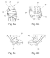
- FIG. 8 a is a bottom view of a shoe comprising studs and strain sections according to yet other alternative embodiments of the present invention.
- FIG. 8 b is a bottom perspective view of the shoe of FIG. 8 a.
- FIG. 8 c is a side view of the shoe of FIG. 8 a in a flexed position.
- FIG. 8 d is another side view of the shoe of FIG. 8 a in a flexed position.
- Embodiments of the invention provide studs for use with a studded shoe. While the studs and studded shoes are discussed for use with sports shoes, they are by no means so limited. Rather, embodiments of the studs and studded shoes may be used in any type of shoe or otherwise as desired.
- FIG. 1 shows a schematic drawing of a human foot 1 .
- the phalanges define different bending areas of the foot; two lines have been highlighted with numbers 3 and 5 .
- Line 3 shows a bending area that is defined by four phalanges and line 5 shows a bending area defined by two phalanges.
- lines 3 and 5 show the bending areas.
- the bending area 9 extends over the full area of both lines 3 and 5 .
- FIGS. 2 a - d and 3 a - b illustrate a variety of possible embodiments of the design of shoe soles and studs comprising a strain section.
- a shoe sole 20 is illustrated, which comprises a plurality of stud receiving devices 22 and studs 24 .
- at least one first strain section 26 may extend through at least one stud 24 .
- the first strain section 26 has substantially a shape of a strip.
- the first strain section 26 may be configured to have a shape that substantially corresponds to a strip, wedge, or other suitable shape.
- some studs 24 may not include any first strain sections 26 .
- a single first strain section 26 may extend through the stud 24 .
- the stud 24 may comprise a first stud portion 50 and a second stud portion 52 , wherein the strain section 26 connects both stud portions 50 , 52 .
- two strain sections may extend through the stud 24 .
- the stud 24 may comprise the first stud portion 50 , the second stud portion 52 , and a third stud portion 54 , wherein the strain sections 70 , 72 connect the stud portions 50 , 52 , 54 .
- the use of multiple stud portions 50 , 52 , 54 to form the stud 24 can provide for easier manufacturing and assembly through a single production step.
- the strain sections 70 , 72 are wedge-shaped and are connected to one another via at least one material ridge 79 .
- the strain sections 70 , 72 may be configured to have a shape that substantially corresponds to a strip, wedge, or other suitable shape.
- the material ridge 79 may, but not necessarily, be formed of a stretchable material.
- the configuration of strain sections 70 , 72 , and material ridge 79 allows for an easier assembly of the strain sections 70 , 72 through a single production step.
- the strain sections 70 , 72 may be placed into the separately manufactured (e.g., using injection molding techniques) shoe sole 20 or the stud receiving device 22 and the stud 24 , and subsequently attached thereto.
- three strain sections may extend through the stud 24 .
- any suitable number of strain sections may extend through any suitable number of studs 24 .
- At least one third strain section 62 may extend over at least one stud 24 , through at least one stud receiving device 22 , and/or beyond the stud receiving device 22 through at least part of the shoe sole 20 . In some embodiments, some studs 24 and/or stud receiving devices 22 may not include any third strain sections 62 .
- a single third strain section 62 may extend over the stud 24 , through the stud receiving device 22 , and/or beyond the stud receiving device 22 .
- the third strain section 62 which extends over the stud 24 itself, may be visible at each end of the first strain section 26 .
- the third strain section 62 has substantially a shape of a strip.
- the third strain section 62 may be configured to have a shape that substantially corresponds to a strip, wedge, or other suitable shape
- three third strain sections 62 may extend over the stud 24 , through the stud receiving device 22 , and/or beyond the stud receiving device 22 through at least part the shoe sole 20 .
- any suitable number of third strain sections 62 may extend through and/or beyond any suitable number of studs 24 and/or stud receiving devices 22 .
- the first strain sections 60 and the second strain section 61 of the stud 24 and the third strain sections 62 of the stud receiving device 22 can be formed integrally. However, it is also possible to build the strain sections separately.
- the studs 24 may have the same or different numbers of strain sections. The number of strain sections in each stud 24 may depend on the position and the specific requirements.
- each stud 24 may be adjusted to the expected movements based on the type and number of third strain sections 62 associated with each stud 24 and/or stud receiving device 22 .
- the studs 24 attached to the shoe sole 20 may have the same or different shapes.
- At least one fourth strain section 53 may extend through at least a portion of the bending area 9 (shown in FIG. 1 ) of the shoe sole 20 , which does not include either studs 24 or stud receiving devices 22 .
- two fourth strain sections 53 extend through areas of the shoe sole 20 that do not include studs 24 or stud receiving devices 22 .
- any suitable number of fourth strain sections 53 may extend through any suitable number of areas of the shoe sole 20 . In the embodiments shown in FIGS.
- the fourth strain section 53 has substantially a shape of a strip.
- the fourth strain section 53 may be configured to have a shape that substantially corresponds to a strip, wedge, or other suitable shape.
- the shoe sole 20 may comprise any suitable number of first ( 26 , 60 , 70 ), second ( 61 , 72 ), third ( 62 ) and/or fourth ( 53 ) strain sections in any suitable location, including but not limited to extending through some or all of the studs 24 , the stud receiving devices 22 , and/or the shoe sole 20 itself.
- the first ( 26 , 60 , 70 ), second ( 61 , 72 ), third ( 62 ) and/or fourth ( 53 ) strain sections may be adapted to the anatomy of the foot, in order to achieve optimal bending and flexibility. These strain sections may lead to a small strain in a dorsal movement of the foot and, therefore, to an improved and more flexible rolling-off of the foot.
- the strain sections can be arranged such that they generally extend perpendicular to a longitudinal axis of the shoe sole 20 . Because of the anatomy of the foot (cf. FIG. 1 ), the strain sections may be arranged in different angles with respect to the longitudinal axis of the shoe sole 20 , as illustrated in FIGS. 2 a - d.
- the first ( 26 , 60 , 70 ), second ( 61 , 72 ), third ( 62 ) and/or fourth ( 53 ) strain sections can be placed within the bending area 9 of the shoe sole 20 , which is the area of the shoe sole 20 that primarily needs higher flexibility.
- FIGS. 3 a - b illustrate embodiments having the fourth strain section 53 in the bending area 9 of the shoe sole 20 , which does extend through a stud 24 or a stud receiving device 22 .
- These strain sections are also adapted to the anatomy of the foot.
- Embodiments such as the embodiments shown in FIGS. 8 a - d , include a studded shoe 80 with differently arranged strain sections 26 , 53 .
- the strain sections 26 may, but not necessarily, extend beyond a stud 24 into the shoe sole 20 , but not over the full width of the shoe sole 20 .
- strain sections 26 , 53 extending over the full width may be advantageous.
- the strain sections 26 , 53 are arranged according to the bending areas of the foot when moved in a dorsal direction, such as illustrated in FIGS. 8 c - d , where the strain when rolling-off of the foot may be seen.
- the strain of the strain section 26 may be restricted through a rigid piece of material, which could form a dead stop and thus restrict a strain.
- This piece of material could be stick-shaped and replaceable or retrofittably positioned in a drill hole of the stud 24 .
- the drill hole should preferably be directed in a longitudinal direction of the shoe.
- FIGS. 2 c - d , 3 a - b , and 5 a - b illustrate that some of the studs 24 and/or the stud receiving devices 22 may not comprise a strain section 26 , 62 , which may be the case for studs 24 arranged in the heel area of the shoe sole 20 (not shown), but also in the area of the big toe. Such studs 24 may also be used for accelerating, in which case, strain sections 26 , 53 , 62 may not be necessary.
- FIGS. 3 a - 3 b illustrate an embodiment of the same shoe sole 20 from two perspectives.
- the strain sections 26 , 53 , 62 extend through the shoe sole 20 , i.e., from an upper side to a lower side.
- the strain sections 26 , 53 , 62 can be fan-shaped (three “strips”) in order to fit the bending area 9 of the feet optimally. Since the medial bending radius is smaller than the lateral bending radius, the fan extends from the medial to the lateral side. In other words, the distance between the strips is larger at the lateral side compared to the medial side.
- Some embodiments may include longitudinal grooves 25 for stabilizing the shoe sole 20 in longitudinal direction. Moreover, interruptions 30 (“stability breaks”) between the first ( 26 , 60 , 70 ), second ( 61 , 72 ), third ( 62 ) and/or fourth ( 53 ) strain sections may be included to increase the stability of the shoe sole 20 .
- the shoe sole 20 is manufactured using an injection molding technique.
- the embodiments having an arrangement of the strain sections 26 , 53 , which do not extend over the full width of the shoe sole 20 , but comprise interruptions 30 allow for a simplified manufacturing in a single step, e.g., using multiple component injection molding. By using the interruptions 30 , no interruptions of the flow of material for the shoe sole 20 is necessary. Further, these embodiments show studs 24 without strain sections 26 , 53 in the heel area and in the area of the big toe. Depending on the respective requirements, the strain sections 26 , 53 , 62 could also extend differently.
- the material, the placement, and/or the dimensions of the studs 24 or the first ( 26 , 60 , 70 ), second ( 61 , 72 ), third ( 62 ) and/or fourth ( 53 ) strain sections may influence the flexibility and the construction of the respective strain sections.
- perforations or other material weakening can allow a stretching of material and consequently create a strain section.
- a further possible construction comprises an embodiment similar to a bellow. In these embodiments, the bellow can be stretched under the influence of a force.
- the shoe sole 20 , the studs 24 , the stud receiving devices 22 , and/or the first ( 26 , 60 , 70 ), second ( 61 , 72 ), third ( 62 ) or fourth ( 53 ) strain sections may be manufactured using two- or multiple component injection molding.
- three components for the shoe sole 20 , the stud receiving device 22 , the strain sections 26 , 53 , 62 , and the studs 24 are used.
- Possible components include but are not limited to thermoplastic elastomers (TPE, TPU), polyamides, Polyether Block Amids (PEBAs) of different hardness and elasticity, or other suitable materials. In order to avoid a a feeling of instability, the respective components should not be too soft.
- the studs 24 and the first ( 26 , 60 , 70 ), second ( 61 , 72 ), third ( 62 ) or fourth ( 53 ) strain sections may be manufactured from the same material such as TPE, TPU or PEBA, in respectively different mixtures yielding different material properties. Similar materials provide a particularly good composite. To increase the stability in areas outside the strain sections, fiber-reinforced composite materials can be used. Alternatively, one or more of the strain sections could be made in a first step, then positioned within a mold, and the shoe sole 20 and the stud 24 could be injected around these strain sections.
- first ( 26 , 60 , 70 ), second ( 61 , 72 ), third ( 62 ) and/or fourth ( 53 ) strain sections, the studs 24 , and the shoe sole 20 could be manufactured separately in a first step and then assembled in a subsequent second step.
- Possible methods include but are not limited to gluing, laser welding, ultrasonic welding, releasable mechanic connections, or other suitable attachment methods.
- the studs may be made of TPU and positioned in a mold, and the material of the strain sections may be made in a second step. These steps may be performed separately or connectedly.
- the strain sections may then be inserted or directly injection molded.
- the stud areas and the strain sections are then injection molded with TPU or PA of the shoe sole.
- Another option may be to first build the stud areas, then the shoe sole, and finally insert the strain sections into the respective cavities.
Landscapes
- Health & Medical Sciences (AREA)
- General Health & Medical Sciences (AREA)
- Physical Education & Sports Medicine (AREA)
- Footwear And Its Accessory, Manufacturing Method And Apparatuses (AREA)
Abstract
Description
- This application is related to and claims priority benefits from German Patent Application Serial No. 10 2010 040 964, filed on Sep. 17, 2010, the entire disclosure of which is hereby incorporated by this reference.
- The field of the invention relates to a stud for a studded shoe, a shoe sole and a studded shoe.
- Studs and studded shoes, such as shoes used in football, are commonly used to provide a good grip and traction on soft ground, such as turf. For example, studded shoes comprise studs which can penetrate the ground and prevent the studded shoe from sliding above the ground.
- In football and other sports, the soil conditions of the respective playing fields may vary. This variation may be due to external influences, such as rain, whereby the ground is softened. On the other hand, the ground may be very dry and hard. Variations in surface conditions may also be present across different sections of a field. These variations may include small bumps or even larger depressions.
- Therefore different types of studs and studded shoes have been developed. The studs typically have a rotationally-symmetric shape but may also have different shapes, such as a triangular or elongated shape. The stud shape allows for quick changes of speed or direction, as typically occurs in football and many other sports.
- In the past, studs or studded shoes have been developed in order to provide an improved power transmission or to provide an ability to adapt to different ground conditions. For example, International Publication No. WO 03/071893 discloses a studded shoe in which several studs are connected via springs. For example,
FIG. 3 a shows that a larger stud may penetrate soft ground and no force is transmitted via the springs to other studs connected with the first stud. On the other hand,FIG. 3 b shows that on hard ground the stud is pushed into the direction of the sole, so that the springs transmit a force to the smaller studs, which are then pushed away in order to improve the grip with the ground. - Great Britain Publication No. 2425706 A discloses a football shoe comprising a sole with studs, which may move independently from each other in the forefoot area of the sole. In this example, the studs are attached to segmented elements. See
FIG. 3 . The segmented elements are attached to an elastic layer of the sole which may stretch under pressure, thus allowing the studs to move. Similarly, U.S. Pat. No. 5,384,973 discloses a sole with spikes wherein single segments of the sole are separated, allowing for an independent movement of the segments. SeeFIG. 27 . - U.S. Pat. No. 3,593,436 discloses a sole for a sports shoe, which is manufactured from a single piece of an elastic material. The sole comprises a plurality of studs that extend downwards from the sole. The disclosed shoe is useful for providing a good grip on synthetic turf, which does not damage the turf.
- German Patent No. 298 07 086 U1 relates to a stud that comprises a movable core. In this example, the movable core is built into the stud and may be pushed outwards via a spring. Thus, depending on the properties of the ground, the stud may enter the ground.
- European Patent No. 1 857 006 A1 relates to situations where the force exerted onto individual studs leads to deformation of the sole, which may be uncomfortable to the athlete wearing the shoe. The discomfort experienced by the athlete may be reduced by grouping several studs, which avoids movement of a single stud. The problem of cushioning forces in axial direction is also addressed in German Patent No. 41 23 302, which teaches the use of a cushioning hook element to increase the comfort of the athlete.
- German Patent No. 2 313 646 also addresses this problem via use of a stud having a holding element and a supporting element. An intermediate element is attached between these elements, which supports elastic movement of the supporting element in the supporting direction.
- European Patent No. 0 356 637 B1 is also directed to improving the cushioning of sports shoes having a sole with studs. In this example, angular bodies are attached to the studs, which may lead to deformation and, thus, cushioning under non-axial forces.
- U.S. Pat. No. 5,505,012 discloses the use of so-called bumpers, which are used to attach the studs to the sole as a way of reducing the force between the sole and the studs.
- German Patent No. 196 52 462 A1 relates to a sole with different zones of rigidity, which may improve rolling-off of the foot.
- U.S. Pat. No. 5,617,653 relates to attaching studs to sports shoes. In this example, when a certain force is exceeded, the studs may be released from the shoe in order to prevent injuries.
- German Patent No. 34 33 337 A1 is directed to a system of two studs, which serve to improve the wearing comfort.
- The prior art, however, does not provide a solution that provides both improved traction and flexibility. For example, the attachment of studs to the sole leads to an increased rigidity of the sole in the area of the attachment, which is especially true for studs that are not rotationally-symmetric. Such studs may be better suited than rotationally-symmetric studs for quick changes of direction, but asymmetric studs generally have a larger attachment area that considerably increases the rigidity of the sole in that area. As a result, in many cases, studs are not attached to the shoe in the bending area of the shoe The absence of studs in the bending area increases flexibility and improved wearing comfort, but reduces grip.
- In other cases, studs are attached to the bending area for an improved grip, which in turn reduces flexibility. This configuration reduces wearing comfort and may also lead to reduced traction since the foot cannot be rolled-off optimally. Hence, known studded shoes are generally built to provide good traction, which results in reduced flexibility of the shoe in the bending area. As a result, movements such as acceleration as required in sports such as football become more difficult for an athlete.
- The technical problem underlying the present invention is therefore to provide a stud, a shoe sole, and a studded shoe that at least partially overcomes the disadvantages of the prior art so that good traction and improved flexibility of the sole are possible.
- Embodiments of the present invention include a stud for a shoe sole comprising at least a first stud portion and a second stud portion, and at least one first strain section, which connects the first stud portion and the second stud portion to each other, wherein the at least one first strain section is configured to be strained when the stud is coupled to the shoe sole and the shoe sole is bent.
- Contrary to the prior art, the construction of such a stud provides a shoe sole with one or more studs also in the bending area of the shoe sole, e.g., in the area of the forefoot between the ball of the foot and the phalanges. This design allows for an improved traction and, thus, power transmission between foot and ground. The at least one first strain section enables the stud to adapt at least partially to the bending of the shoe sole in a dorsal direction. Thus, the comfort of the athlete is not reduced even under great forces. In particular, rolling off of the foot causes bending of the shoe sole. Thereby, outer portions of the stud are bent more significantly than inner portions. The inclusion of the at least one first strain section allows for such a strain because, without the at least one first strain section, the stud is rigid, which contributed to the problems of the prior art. In particular, the athlete may use his force more efficiently, since this advantageous approach allows for placing studs in the bending area of the foot, which consequently leads to better adaptation to ground conditions and improved transmission of force. Embodiments of the present invention are suitable for all shapes of studs, especially for elongated or asymmetric shapes. Suitable studs therefore include components that are optimised for different tasks. While portions of the stud offer the required grip with the ground and therefore may be made of a rigid material, the connecting strain section alleviates rolling off of the foot by enabling a strain of the stud, which can adapt to the bending of the shoe sole. According to certain embodiments, the strain section may also penetrate the ground.
- In certain embodiments, the first stud portion and the second stud portion are connected to each other only by the at least one first strain section. These embodiments allow for maximized strain flexibility, since there are no non-elastic areas between the portions that could prevent a strain. Moreover, the portions are connected to each other at least indirectly via a stud attachment device and/or the shoe sole. However, these indirect connections have no influence on strain of the stud when the shoe sole bends.
- In other embodiments, the first stud portion and the second stud portion are additionally connected to each other through a material ridge. Connecting the first stud portion and the second stud portion reduces the bending flexibility, but also allows for a more stable construction of the stud. For certain types of studs, positions of studs, or certain purposes, having a more stable construction may be more important than providing maximum bending flexibility. For example, a more rigid stud at the tip and/or the heel of a shoe sole may be advantageous. Moreover, the material ridge allows for an easier production, since the stud can be built integrally and can be made from fewer components. Further, depending on the use case, it is possible to reduce the strain or to create a dead stop.
- In other embodiments, the first stud portion, the second stud portion, and the at least one first strain section are integrally formed. The first stud portion and the second stud portion may be assembled in a single step. Such an assembly advantageously reduces the required number of components.
- In certain embodiments, the at least one first strain section comprises an angle of 45 degrees to 90 degrees with a surface of the shoe sole. Arranging the at least one first strain section at a certain angle allows for adapting to specific conditions, e.g., certain studs may experience specific loads which require an inclination of the strain section in order to fully exploit the advantageous properties of the particular stud.
- According to certain embodiments, the at least one first strain section extends substantially perpendicular to a tangent plane proximate an area of the shoe sole where the stud is configured to be coupled to the shoe sole. This configuration allows for a bending of the stud—and thus of the shoe sole—if the foot is bent in dorsal direction. As a result, this configuration allows for an easier rolling-off of the foot, since the shoe sole is more flexible, without waiving the improved traction of additional studs in the bending area of the shoe sole. Different orientations of the strain section are also possible. The at least one first strain section may be optimized with respect to the bending properties of the respective shoe sole. For example, certain sports may require bending the shoe sole in a lateral direction and, thus, may require one or more studs in that area. In this case, the at least one first strain section may be such that a lateral rolling-off of the foot is hindered as little as possible.
- In certain embodiments, the at least one first strain section has substantially a shape of a strip. This kind of strain section is easy to build and assemble with other parts of the stud.
- In other embodiments, the at least one first strain section is wedge-shaped. The wedge shape allows for an improved alignment of the stud when rolling-off of the foot. Preferably, in a lateral view, the wedge is arranged such that the wider end points towards the ground, since the outer portions of the strain section experience a greater strain than the inner portions, i.e., the portions nearer to the shoe sole. This enables a particularly good adaptation of the stud, and the strain section is not overstressed. Moreover, other shapes of strain sections are possible, depending on the respective use case.
- In certain embodiments, the stud further comprises a second strain section and a third stud portion, wherein the second strain section connects the second stud portion and the third stud portion to each other, and the second strain section is configured to be strained when the stud is coupled to the shoe sole and the shoe sole is bent. By adding another strain section, additional adaptations to the bending of the shoe sole are possible. In these embodiments, an improved bending of the shoe sole, even in the bending area of the shoe sole, can be achieved. Adding further strain sections and portions to the stud may also be desirable.
- In other embodiments, the at least one first strain section and the second strain section extend substantially parallel to each other. These embodiments allow for a smooth bending of the stud. It is further possible to arrange the at least one first strain section and the second strain section perpendicular to each other. Thereby, the at least one first strain section is arranged perpendicular to the longitudinal axis and the second strain section is arranged parallel to the longitudinal axis. This configuration allows for a strain in longitudinal and transverse direction. The second strain section could also be arranged parallel to the shoe sole, i.e., horizontally in the stud, and allow for cushioning in axial direction (as known from the prior art). Also, a combination of all three strain sections is possible.
- In some embodiments, the at least one first and the second strain section are connected to each other through at least one material ridge made of stretchable material. Such an embodiment allows simplified assembly (e.g., using molding techniques) and further affects the flexibility, since the stud comprises more stretchable, elastic material.
- In other embodiments, the at least one first strain section and the second strain section are integrally formed. The at least one first strain section and the second strain section may be assembled in one step. A material ridge may connect the at least one first strain section and the second strain section to each other. When manufacturing the stud and the shoe sole, e.g. using injection molding techniques, a lower number of pieces may be advantageous.
- According to additional embodiments, the present invention relates to a shoe sole comprising at least one stud for the shoe sole, wherein the at least one stud comprises at least a first stud portion a second stud portion, and at least one first strain section, which connects the first stud portion and the second stud portion to each other, wherein the at least one first strain section is configured to be strained when the stud is coupled to the shoe sole and the shoe sole is bent. Such a shoe sole offers improved bending properties compared with conventional shoe soles featuring rigid studs. This result is particularly present when one or more studs are arranged in the bending area of the shoe sole.
- In other embodiments, the present invention relates to a studded shoe comprising a shoe sole comprising at least one stud for the shoe sole, wherein the at least one stud at least a first stud portion a second stud portion, and at least one first strain section, which connects the first stud portion and the second stud portion to each other, wherein the at least one first strain section is configured to be strained when the stud is coupled to the shoe sole and the shoe sole is bent. By using a shoe sole according to the present invention, studded shoes, in particular football shoes, are provided which have an improved flexibility in the bending area. Furthermore, at the same time, the studs also provide better traction.
- According to additional embodiments, the present invention relates to a shoe sole comprising at least one stud for the shoe sole, wherein the at least one stud comprises a first stud portion, a second stud portion, a third stud portion, at least one first strain section, which connects the first stud portion and the second stud portion to each other, and a second strain section, which connects the second stud portion and the third stud portion to each other, wherein the at least one first strain section and the second strain section are configured to be strained when the at least one stud is coupled to the shoe sole and the shoe sole is bent. Such a shoe sole offers improved bending properties compared with conventional shoe soles featuring rigid studs. This result is particularly present when one or more studs are arranged in the bending area of the shoe sole.
- In certain embodiments, the shoe sole further comprises at least one stud receiving device comprising at least one third strain section. The at least one third strain section is particularly desirable in the bending area of the shoe sole, if the rolling area extends transverse to the longitudinal direction of the shoe sole. Modern studs usually are not bolted to the shoe sole, but are instead coupled in custom-built stud receiving devices, e.g., by using a clip mechanism, bolting, magnetic mechanisms, other mechanisms, or even by permanently gluing, molding, or riveting. The stud receiving devices and/or studs may also be formed integrally together with the shoe sole. Such stud receiving devices already lead to a higher rigidity of the shoe sole and therefore may hinder a bending of the shoe sole. Accordingly, by adding another strain section to the stud receiving devices, the bending flexibility of the shoe sole can be further improved. This result holds true for both a stud that is releasably coupled to the stud receiving device, as well as a stud that is permanently coupled to the stud receiving device.
- In other embodiments, the at least one third strain section extends beyond the at least one stud receiving device into the shoe sole. Since the bending of the foot extends over the full width of the shoe sole, a further extension of the at least one third strain section in a lateral direction beyond the stud receiving device is preferred, in order to optimally support rolling-off of the foot and exploit the mentioned advantages of the various embodiments. However, different attachments of at least one third strain section are possible, which may depend for instance on the rolling off behavior of the foot.
- In other embodiments, the at least one first strain section and the at least one third strain section are integrally formed. Again, this integral formation allows for an easier production and assembly of the shoe sole.
- In other embodiments, the shoe sole further comprises at least one fourth strain section, which is positioned in an area of the shoe sole without a stud. Attaching at least one fourth strain section in a transverse direction of the shoe sole may also improve the flexibility when bending the shoe sole in dorsal direction. Moreover, different attachments of the at least one fourth strain section are possible, e.g., in direction of a longitudinal axis of the shoe sole. Such a strain section in longitudinal direction is particularly helpful in the tip of the foot or the forefoot area, e.g., between the second and the third phalanges. This strain section enables an improved adaptation of the shoe to the ground and provides more stability.
- In other embodiments, the at least one first strain section, the second strain section, the at least one third strain section, or the at least one fourth strain section is positioned in a bending area of the shoe sole. Typically, improved flexibility of the shoe sole is required in the bending area, e.g., in the area of the forefoot. Of course, it may also be advantageous to include strain sections at other positions of the shoe sole, as already mentioned above.
- In certain embodiments, the shoe sole, the at least one stud, the first stud portion, the second stud portion, the third stud portion, the at least one first strain section, and the second strain section are integrally formed. Using modern production techniques (e.g. multiple component injection molding), it is possible to produce shoe soles from different materials. For example, a first material can be used for the various strain sections on the one hand and another material can be used for the other portions of the stud and/or the shoe sole on the other hand. This leads to a clearly reduced complexity of the production of the shoe sole. However, it is also possible to provide the above mentioned features within a stud and a shoe sole, which are releasably attached to each other such that the stud may be exchanged.
- Finally, embodiments of the present invention relate to a studded shoe comprising a shoe sole comprising at least one stud for the shoe sole, wherein the at least one stud comprises a first stud portion, a second stud portion, a third stud portion, at least one first strain section, which connects the first stud portion and the second stud portion to each other, and a second strain section, which connects the second stud portion and the third stud portion to each other, wherein the at least one first strain section and the second strain section are configured to be strained when the at least one stud is coupled to the shoe sole and the shoe sole is bent. By using a shoe sole according to the present invention, studded shoes, in particular football shoes, are provided which have an improved flexibility in the bending area. Furthermore, at the same time, the studs also provide better traction.
-
FIG. 1 is a schematic top view of a foot according to certain embodiments of the present invention. -
FIG. 2 a is a schematic bottom view of a shoe sole according to certain embodiments of the present invention. -
FIG. 2 b is a schematic bottom view of a shoe sole according to alternative embodiments of the present invention. -
FIG. 2 c is a schematic bottom view of a shoe sole according to other alternative embodiments of the present invention. -
FIG. 2 d is a schematic bottom view of a shoe sole according to yet other alternative embodiments of the present invention. -
FIG. 3 a is a bottom view of a shoe sole comprising studs and strain sections according to yet other alternative embodiments of the present invention. -
FIG. 3 b is a top view of the shoe sole ofFIG. 3 a. -
FIG. 4 a is a side view of the shoe sole ofFIG. 3 a. -
FIG. 4 b is another side view of the shoe sole ofFIG. 3 a. -
FIG. 5 a is a partial bottom view of the shoe sole ofFIG. 3 a. -
FIG. 5 b is another partial bottom view of the shoe sole ofFIG. 3 a. -
FIG. 6 a is side view of a shoe sole comprising studs and strain sections according to yet other alternative embodiments of the present invention. -
FIG. 6 b is bottom view of the single stud and the shoe sole ofFIG. 6 a. -
FIG. 7 a is a side perspective view a shoe sole comprising studs and strain sections according to yet other alternative embodiments of the present invention. -
FIG. 7 b is an exploded side perspective view of the single stud and the shoe sole ofFIG. 7 a. -
FIG. 8 a is a bottom view of a shoe comprising studs and strain sections according to yet other alternative embodiments of the present invention. -
FIG. 8 b is a bottom perspective view of the shoe ofFIG. 8 a. -
FIG. 8 c is a side view of the shoe ofFIG. 8 a in a flexed position. -
FIG. 8 d is another side view of the shoe ofFIG. 8 a in a flexed position. - Embodiments of the invention provide studs for use with a studded shoe. While the studs and studded shoes are discussed for use with sports shoes, they are by no means so limited. Rather, embodiments of the studs and studded shoes may be used in any type of shoe or otherwise as desired.
-
FIG. 1 shows a schematic drawing of a human foot 1. The phalanges define different bending areas of the foot; two lines have been highlighted withnumbers Line 3 shows a bending area that is defined by four phalanges andline 5 shows a bending area defined by two phalanges. When rolling-off of the foot, the toes are bent, andlines lines -
FIGS. 2 a-d and 3 a-b illustrate a variety of possible embodiments of the design of shoe soles and studs comprising a strain section. In these embodiments, a shoe sole 20 is illustrated, which comprises a plurality ofstud receiving devices 22 andstuds 24. In some embodiments, at least onefirst strain section 26 may extend through at least onestud 24. In the embodiments shown inFIGS. 2 a-d, 3 a-b, 4 a-b, and 5 a-b, thefirst strain section 26 has substantially a shape of a strip. However, one of ordinary skill in the relevant art will understand that thefirst strain section 26 may be configured to have a shape that substantially corresponds to a strip, wedge, or other suitable shape. In these embodiments, somestuds 24 may not include anyfirst strain sections 26. - As shown in
FIGS. 2 a-d, 3 a-b, 4 a-b, and 5 a-b, a singlefirst strain section 26 may extend through thestud 24. In these embodiments, as illustrated inFIGS. 5 a-b, thestud 24 may comprise afirst stud portion 50 and asecond stud portion 52, wherein thestrain section 26 connects bothstud portions - In other embodiments, as shown in
FIGS. 7 a-b, two strain sections (afirst strain section 70 and a second strain section 72) may extend through thestud 24. In these embodiments, thestud 24 may comprise thefirst stud portion 50, thesecond stud portion 52, and athird stud portion 54, wherein thestrain sections stud portions multiple stud portions stud 24 can provide for easier manufacturing and assembly through a single production step. - In the embodiments shown in
FIGS. 7 a-b, thestrain sections material ridge 79. However, one of ordinary skill in the relevant art will understand that thestrain sections material ridge 79 may, but not necessarily, be formed of a stretchable material. In some instances, the configuration ofstrain sections material ridge 79 allows for an easier assembly of thestrain sections strain sections stud receiving device 22 and thestud 24, and subsequently attached thereto. - In yet other embodiments, as shown in
FIGS. 6 a-b, three strain sections (two first strain sections 60 and a second strain section 61) may extend through thestud 24. One of skill in the relevant art will understand that any suitable number of strain sections may extend through any suitable number ofstuds 24. - In some embodiments, as shown in
FIGS. 3 a-b, 4 a-b, 5 a-b, and 6 a-b, at least onethird strain section 62 may extend over at least onestud 24, through at least onestud receiving device 22, and/or beyond thestud receiving device 22 through at least part of theshoe sole 20. In some embodiments, somestuds 24 and/orstud receiving devices 22 may not include anythird strain sections 62. - In the embodiments shown in
FIGS. 3 a-b, 4 a-b, and 5 a-b, a singlethird strain section 62 may extend over thestud 24, through thestud receiving device 22, and/or beyond thestud receiving device 22. In these embodiments, thethird strain section 62, which extends over thestud 24 itself, may be visible at each end of thefirst strain section 26. In the embodiments shown inFIGS. 3 a-b and 4 a-b, thethird strain section 62 has substantially a shape of a strip. However, one of ordinary skill in the relevant art will understand that thethird strain section 62 may be configured to have a shape that substantially corresponds to a strip, wedge, or other suitable shape - In other embodiments, as shown in
FIGS. 6 a-b, threethird strain sections 62 may extend over thestud 24, through thestud receiving device 22, and/or beyond thestud receiving device 22 through at least part theshoe sole 20. One of skill in the relevant art will understand that any suitable number ofthird strain sections 62 may extend through and/or beyond any suitable number ofstuds 24 and/orstud receiving devices 22. - As illustrated in
FIGS. 6 a-b, the first strain sections 60 and the second strain section 61 of thestud 24 and thethird strain sections 62 of thestud receiving device 22 can be formed integrally. However, it is also possible to build the strain sections separately. Thestuds 24 may have the same or different numbers of strain sections. The number of strain sections in eachstud 24 may depend on the position and the specific requirements. - The flexibility of each
stud 24 may be adjusted to the expected movements based on the type and number ofthird strain sections 62 associated with eachstud 24 and/orstud receiving device 22. In these embodiments, thestuds 24 attached to the shoe sole 20 may have the same or different shapes. - In some embodiments, at least one
fourth strain section 53 may extend through at least a portion of the bending area 9 (shown inFIG. 1 ) of the shoe sole 20, which does not include eitherstuds 24 orstud receiving devices 22. As shown inFIGS. 2 a, 3 a-b, and 4 a, twofourth strain sections 53 extend through areas of the shoe sole 20 that do not includestuds 24 orstud receiving devices 22. One of ordinary skill in the relevant art will understand that any suitable number offourth strain sections 53 may extend through any suitable number of areas of theshoe sole 20. In the embodiments shown inFIGS. 2 a, 3 a-b, 4 a, and 5 a-b, thefourth strain section 53 has substantially a shape of a strip. However, one of ordinary skill in the relevant art will understand that thefourth strain section 53 may be configured to have a shape that substantially corresponds to a strip, wedge, or other suitable shape. - Hence, the shoe sole 20 may comprise any suitable number of first (26, 60, 70), second (61, 72), third (62) and/or fourth (53) strain sections in any suitable location, including but not limited to extending through some or all of the
studs 24, thestud receiving devices 22, and/or the shoe sole 20 itself. - In some embodiments, the first (26, 60, 70), second (61, 72), third (62) and/or fourth (53) strain sections may be adapted to the anatomy of the foot, in order to achieve optimal bending and flexibility. These strain sections may lead to a small strain in a dorsal movement of the foot and, therefore, to an improved and more flexible rolling-off of the foot. The strain sections can be arranged such that they generally extend perpendicular to a longitudinal axis of the
shoe sole 20. Because of the anatomy of the foot (cf.FIG. 1 ), the strain sections may be arranged in different angles with respect to the longitudinal axis of the shoe sole 20, as illustrated inFIGS. 2 a-d. - In these embodiments, the first (26, 60, 70), second (61, 72), third (62) and/or fourth (53) strain sections can be placed within the bending area 9 of the shoe sole 20, which is the area of the shoe sole 20 that primarily needs higher flexibility.
FIGS. 3 a-b illustrate embodiments having thefourth strain section 53 in the bending area 9 of the shoe sole 20, which does extend through astud 24 or astud receiving device 22. These strain sections are also adapted to the anatomy of the foot. - Embodiments, such as the embodiments shown in
FIGS. 8 a-d, include astudded shoe 80 with differently arrangedstrain sections strain sections 26 may, but not necessarily, extend beyond astud 24 into the shoe sole 20, but not over the full width of theshoe sole 20. Depending on the respective use case, in other embodiments,strain sections strain sections FIGS. 8 c-d, where the strain when rolling-off of the foot may be seen. By flexing the foot more, outer portions of thestud 24 experience a larger strain than portions that are nearer to the shoe sole 20, which is shown, for example, inFIGS. 8 c-d. Due to the rolling off of the foot, thestrain sections 26 are more strongly bent at the lower end, which may result in a wedge shape. However, thestrain sections 26 shown inFIG. 8 a-b could already be substantially strip- or wedge-shaped in a relaxed state. - In other embodiments, it is further possible that the strain of the
strain section 26 may be restricted through a rigid piece of material, which could form a dead stop and thus restrict a strain. This piece of material could be stick-shaped and replaceable or retrofittably positioned in a drill hole of thestud 24. The drill hole should preferably be directed in a longitudinal direction of the shoe. -
FIGS. 2 c-d, 3 a-b, and 5 a-b illustrate that some of thestuds 24 and/or thestud receiving devices 22 may not comprise astrain section studs 24 arranged in the heel area of the shoe sole 20 (not shown), but also in the area of the big toe.Such studs 24 may also be used for accelerating, in which case,strain sections -
FIGS. 3 a-3 b illustrate an embodiment of the same shoe sole 20 from two perspectives. Thus, as can be seen from these figures, thestrain sections strain sections - Some embodiments may include
longitudinal grooves 25 for stabilizing the shoe sole 20 in longitudinal direction. Moreover, interruptions 30 (“stability breaks”) between the first (26, 60, 70), second (61, 72), third (62) and/or fourth (53) strain sections may be included to increase the stability of theshoe sole 20. - In some embodiments, the
shoe sole 20 is manufactured using an injection molding technique. The embodiments having an arrangement of thestrain sections interruptions 30, allow for a simplified manufacturing in a single step, e.g., using multiple component injection molding. By using theinterruptions 30, no interruptions of the flow of material for theshoe sole 20 is necessary. Further, these embodiments showstuds 24 withoutstrain sections strain sections - In some embodiments, the material, the placement, and/or the dimensions of the
studs 24 or the first (26, 60, 70), second (61, 72), third (62) and/or fourth (53) strain sections may influence the flexibility and the construction of the respective strain sections. For example, perforations or other material weakening can allow a stretching of material and consequently create a strain section. A further possible construction comprises an embodiment similar to a bellow. In these embodiments, the bellow can be stretched under the influence of a force. - The shoe sole 20, the
studs 24, thestud receiving devices 22, and/or the first (26, 60, 70), second (61, 72), third (62) or fourth (53) strain sections may be manufactured using two- or multiple component injection molding. In some exemplary embodiments, three components for the shoe sole 20, thestud receiving device 22, thestrain sections studs 24 are used. Possible components include but are not limited to thermoplastic elastomers (TPE, TPU), polyamides, Polyether Block Amids (PEBAs) of different hardness and elasticity, or other suitable materials. In order to avoid a a feeling of instability, the respective components should not be too soft. - Moreover, the
studs 24 and the first (26, 60, 70), second (61, 72), third (62) or fourth (53) strain sections may be manufactured from the same material such as TPE, TPU or PEBA, in respectively different mixtures yielding different material properties. Similar materials provide a particularly good composite. To increase the stability in areas outside the strain sections, fiber-reinforced composite materials can be used. Alternatively, one or more of the strain sections could be made in a first step, then positioned within a mold, and theshoe sole 20 and thestud 24 could be injected around these strain sections. Furthermore, all parts of the first (26, 60, 70), second (61, 72), third (62) and/or fourth (53) strain sections, thestuds 24, and the shoe sole 20 could be manufactured separately in a first step and then assembled in a subsequent second step. Possible methods include but are not limited to gluing, laser welding, ultrasonic welding, releasable mechanic connections, or other suitable attachment methods. - Two exemplary production methods may be desirable in some embodiments. First, the studs may be made of TPU and positioned in a mold, and the material of the strain sections may be made in a second step. These steps may be performed separately or connectedly. The strain sections may then be inserted or directly injection molded. The stud areas and the strain sections are then injection molded with TPU or PA of the shoe sole. Another option may be to first build the stud areas, then the shoe sole, and finally insert the strain sections into the respective cavities.
- The foregoing is provided for purposes of illustrating, explaining, and describing embodiments of the present invention. Further modifications and adaptations to these embodiments will be apparent to those skilled in the art. The features and aspects of the present invention have been described or depicted by way of example only and are therefore not intended to be interpreted as required or essential elements of the invention unless otherwise so stated. It should be understood, therefore, that the foregoing relates only to certain exemplary embodiments of the invention, and that numerous changes and additions may be made thereto without departing from the spirit and scope of the invention as defined by any appended claims.
Claims (22)
Applications Claiming Priority (2)
| Application Number | Priority Date | Filing Date | Title |
|---|---|---|---|
| DE102010040964.2A DE102010040964B4 (en) | 2010-09-17 | 2010-09-17 | Studs for studded shoe |
| DE102010040964 | 2010-09-17 |
Publications (2)
| Publication Number | Publication Date |
|---|---|
| US20120066933A1 true US20120066933A1 (en) | 2012-03-22 |
| US9468264B2 US9468264B2 (en) | 2016-10-18 |
Family
ID=44582673
Family Applications (1)
| Application Number | Title | Priority Date | Filing Date |
|---|---|---|---|
| US13/222,546 Active 2032-12-09 US9468264B2 (en) | 2010-09-17 | 2011-08-31 | Flexible stud |
Country Status (5)
| Country | Link |
|---|---|
| US (1) | US9468264B2 (en) |
| EP (1) | EP2430937B1 (en) |
| JP (1) | JP5681068B2 (en) |
| CN (1) | CN102406276B (en) |
| DE (1) | DE102010040964B4 (en) |
Cited By (10)
| Publication number | Priority date | Publication date | Assignee | Title |
|---|---|---|---|---|
| DE102012214886A1 (en) * | 2012-08-22 | 2014-02-27 | MAXGUARD GmbH | Bottom portion of shoe, has lugs that are arranged along the running direction to the front of enlarged surface of main structure such that several triangle-shaped side lines that are extended convexly |
| WO2014022260A3 (en) * | 2012-07-30 | 2014-05-01 | Nike International Ltd. | Reinforcing shank arrangement for footwear sole structure |
| US9420851B2 (en) | 2013-12-31 | 2016-08-23 | Nike, Inc. | Footwear having lace receiving strands |
| US9700103B2 (en) | 2013-08-20 | 2017-07-11 | Nike, Inc. | Cleated footwear with flexible cleats |
| US10123588B2 (en) | 2013-12-31 | 2018-11-13 | Nike, Inc. | Footwear ground engaging members having concave portions |
| USD948855S1 (en) * | 2021-03-31 | 2022-04-19 | Nike, Inc. | Shoe |
| USD948856S1 (en) * | 2021-03-31 | 2022-04-19 | Nike, Inc. | Shoe |
| USD971571S1 (en) * | 2020-04-09 | 2022-12-06 | Under Armour, Inc. | Sole structure |
| WO2023141152A1 (en) * | 2022-01-19 | 2023-07-27 | Jalmrr, Llc | Deflectable cleat system for footwear |
| US11752413B2 (en) * | 2016-12-31 | 2023-09-12 | Under Armour, Inc. | Article of footwear with multiple durometer outsole and directional cleat pattern |
Families Citing this family (7)
| Publication number | Priority date | Publication date | Assignee | Title |
|---|---|---|---|---|
| DE202014003299U1 (en) | 2014-04-14 | 2014-08-25 | Antje Koss | Studded shoe with Wechselstollensystem |
| WO2017165376A1 (en) * | 2016-03-22 | 2017-09-28 | Nike Innovate C.V. | Sole structure having a divided cleat |
| CN107157004B (en) * | 2017-06-27 | 2022-11-11 | 特步(中国)有限公司 | Design method of ground-grabbing football shoe outsole and ground-grabbing football shoe outsole |
| USD913663S1 (en) | 2018-03-08 | 2021-03-23 | Adidas Ag | Sole |
| CN114652047B (en) * | 2019-09-03 | 2024-06-21 | 阿迪达斯股份公司 | Sole element |
| US11944158B2 (en) | 2019-09-03 | 2024-04-02 | Adidas Ag | Sole element |
| CN112741394B (en) * | 2020-12-28 | 2022-10-04 | 晋江市创达鞋业有限公司 | High-strength football shoe sole suitable for lawn area and processing technology thereof |
Citations (8)
| Publication number | Priority date | Publication date | Assignee | Title |
|---|---|---|---|---|
| US4283865A (en) * | 1978-01-18 | 1981-08-18 | Adolf Dassler | Outsole for sport shoes |
| US6817117B1 (en) * | 2002-03-05 | 2004-11-16 | Nike, Inc. | Golf shoe outsole with oriented traction elements |
| US7409783B2 (en) * | 2005-11-14 | 2008-08-12 | Vanbestco Ltd. | Spike |
| US20100154258A1 (en) * | 2008-12-23 | 2010-06-24 | Adidas International Marketing B.V. | Sole |
| US8056267B2 (en) * | 2008-05-30 | 2011-11-15 | Nike, Inc. | Article of footwear with cleated sole assembly |
| US8356428B2 (en) * | 2009-10-20 | 2013-01-22 | Nike, Inc. | Article of footwear with flexible reinforcing plate |
| US8453349B2 (en) * | 2009-04-02 | 2013-06-04 | Nike, Inc. | Traction elements |
| US8453354B2 (en) * | 2009-10-01 | 2013-06-04 | Nike, Inc. | Rigid cantilevered stud |
Family Cites Families (23)
| Publication number | Priority date | Publication date | Assignee | Title |
|---|---|---|---|---|
| GB1093107A (en) * | 1965-06-21 | 1967-11-29 | Luther Austin And Sons Ltd | Improvements in or relating to sports shoes |
| US3593436A (en) | 1969-05-29 | 1971-07-20 | Hyde Athletic Ind Inc | Athletic shoe sole |
| DE2313646C3 (en) | 1973-03-19 | 1980-08-14 | Ludwig 7403 Ammerbuch Sailer | Studs for sports shoes, in particular for soccer shoes |
| CH626517A5 (en) * | 1978-01-30 | 1981-11-30 | Dassler Adi Adidas Sportschuhf | Outsole for sports shoe |
| US4669204A (en) | 1983-12-27 | 1987-06-02 | Tanel Corporation | Pivoting athletic shoe |
| DE3433337A1 (en) | 1984-09-11 | 1986-03-20 | Konrad Ed. 8023 Pullach Matulla | Football boot: double stud of flexible construction |
| ATE38314T1 (en) * | 1984-12-01 | 1988-11-15 | Itw Ateco Gmbh | STUD SYSTEM FOR SPORTS BOOTS, ESPECIALLY FOOTBALL BOOTS. |
| DE3833193A1 (en) | 1988-08-29 | 1990-03-08 | Adidas Ag | SPORTSHOE, ESPECIALLY FOOTBALL SHOE |
| US5617653A (en) | 1991-04-15 | 1997-04-08 | Andrew S. Walker | Break-away cleat assembly for athletic shoe |
| DE4123302C2 (en) | 1991-07-13 | 1994-02-10 | Uhl Sportartikel Karl | Gripping element for sports shoe soles |
| US5384973A (en) | 1992-12-11 | 1995-01-31 | Nike, Inc. | Sole with articulated forefoot |
| US5377431A (en) | 1993-06-15 | 1995-01-03 | Walker; Andrew S. | Directionally yieldable cleat assembly |
| US5901472A (en) | 1996-08-01 | 1999-05-11 | Diversified Industrial Technology, Inc. | Athletic shoe system and removable cleat |
| DE19652462C2 (en) | 1996-12-17 | 1999-07-08 | Uhlsystem Deutschland Gmbh | Sole for sports shoes and method for producing such |
| US5819322A (en) | 1997-06-23 | 1998-10-13 | Dicker; Timothy P. | Energy conservative/expenditure garment |
| DE29807086U1 (en) | 1998-04-20 | 1998-07-02 | Luber Josef | Shoe studs with a movable stud core |
| WO2003071893A1 (en) | 2002-02-28 | 2003-09-04 | Generics Investment Group Ag | Adaptive grip |
| GB2425706A (en) | 2005-05-07 | 2006-11-08 | Colm Daniel O'dwyer | Football boot with elasticated sole |
| US7707748B2 (en) * | 2006-02-24 | 2010-05-04 | Nike, Inc. | Flexible foot-support structures and products containing such support structures |
| GB0609808D0 (en) | 2006-05-17 | 2006-06-28 | Berghaus Ltd | Footwear sole |
| ITMO20070205A1 (en) | 2007-06-14 | 2008-12-15 | Lotto Sport Italia Spa | SPORTS SHOE PARTICULARLY FOR LANDS IN SYNTHETIC GRASS |
| WO2010012047A1 (en) | 2008-08-01 | 2010-02-04 | Naismith-Beeley, Ilde | A shoe heel support device |
| SI2361521T1 (en) | 2010-02-25 | 2017-07-31 | Stonefly S.P.A. | Footwear with shock absorbing sole |
-
2010
- 2010-09-17 DE DE102010040964.2A patent/DE102010040964B4/en active Active
-
2011
- 2011-08-31 US US13/222,546 patent/US9468264B2/en active Active
- 2011-08-31 JP JP2011188669A patent/JP5681068B2/en active Active
- 2011-09-09 CN CN201110266932.7A patent/CN102406276B/en not_active Expired - Fee Related
- 2011-09-13 EP EP11181020.6A patent/EP2430937B1/en active Active
Patent Citations (9)
| Publication number | Priority date | Publication date | Assignee | Title |
|---|---|---|---|---|
| US4283865A (en) * | 1978-01-18 | 1981-08-18 | Adolf Dassler | Outsole for sport shoes |
| US6817117B1 (en) * | 2002-03-05 | 2004-11-16 | Nike, Inc. | Golf shoe outsole with oriented traction elements |
| US7409783B2 (en) * | 2005-11-14 | 2008-08-12 | Vanbestco Ltd. | Spike |
| US8056267B2 (en) * | 2008-05-30 | 2011-11-15 | Nike, Inc. | Article of footwear with cleated sole assembly |
| US20100154258A1 (en) * | 2008-12-23 | 2010-06-24 | Adidas International Marketing B.V. | Sole |
| US8522457B2 (en) * | 2008-12-23 | 2013-09-03 | Adidas International Marketing B.V. | Sole |
| US8453349B2 (en) * | 2009-04-02 | 2013-06-04 | Nike, Inc. | Traction elements |
| US8453354B2 (en) * | 2009-10-01 | 2013-06-04 | Nike, Inc. | Rigid cantilevered stud |
| US8356428B2 (en) * | 2009-10-20 | 2013-01-22 | Nike, Inc. | Article of footwear with flexible reinforcing plate |
Cited By (26)
| Publication number | Priority date | Publication date | Assignee | Title |
|---|---|---|---|---|
| US10244820B2 (en) | 2012-07-30 | 2019-04-02 | Nike, Inc. | Reinforcing shank arrangement for footwear sole structure |
| WO2014022260A3 (en) * | 2012-07-30 | 2014-05-01 | Nike International Ltd. | Reinforcing shank arrangement for footwear sole structure |
| US10952495B2 (en) | 2012-07-30 | 2021-03-23 | Nike, Inc. | Reinforcing shank arrangement for footwear sole structure |
| EP3117731A1 (en) * | 2012-07-30 | 2017-01-18 | NIKE Innovate C.V. | Method of making a sole component with a reinforcing shank arrangement for an article of footwear |
| EP3117730A1 (en) * | 2012-07-30 | 2017-01-18 | NIKE Innovate C.V. | Article of footwear including a sole component with a reinforcing shank arrangement, and method of making such a sole component |
| US9675133B2 (en) | 2012-07-30 | 2017-06-13 | Nike, Inc. | Reinforcing shank arrangement for footwear sole structure |
| EP3375315A1 (en) * | 2012-07-30 | 2018-09-19 | NIKE Innovate C.V. | Sole component with a reinforcing shank arrangement, and corresponding article of footwear |
| DE102012214886A1 (en) * | 2012-08-22 | 2014-02-27 | MAXGUARD GmbH | Bottom portion of shoe, has lugs that are arranged along the running direction to the front of enlarged surface of main structure such that several triangle-shaped side lines that are extended convexly |
| US9700103B2 (en) | 2013-08-20 | 2017-07-11 | Nike, Inc. | Cleated footwear with flexible cleats |
| US10932527B2 (en) | 2013-08-20 | 2021-03-02 | Nike, Inc. | Cleated footwear with flexible cleats |
| US12004591B2 (en) | 2013-12-31 | 2024-06-11 | Nike, Inc. | Footwear ground engaging members having concave portions |
| US10098417B2 (en) | 2013-12-31 | 2018-10-16 | Nike, Inc. | Footwear having lace receiving strands |
| US9420851B2 (en) | 2013-12-31 | 2016-08-23 | Nike, Inc. | Footwear having lace receiving strands |
| US11039663B2 (en) | 2013-12-31 | 2021-06-22 | Nike, Inc. | Footwear ground engaging members having concave portions |
| US11058177B2 (en) | 2013-12-31 | 2021-07-13 | Nike, Inc. | Footwear ground engaging members having concave portions |
| US10123588B2 (en) | 2013-12-31 | 2018-11-13 | Nike, Inc. | Footwear ground engaging members having concave portions |
| US11752413B2 (en) * | 2016-12-31 | 2023-09-12 | Under Armour, Inc. | Article of footwear with multiple durometer outsole and directional cleat pattern |
| USD971571S1 (en) * | 2020-04-09 | 2022-12-06 | Under Armour, Inc. | Sole structure |
| USD1065802S1 (en) | 2020-04-09 | 2025-03-11 | Under Armour, Inc. | Sole structure |
| USD948856S1 (en) * | 2021-03-31 | 2022-04-19 | Nike, Inc. | Shoe |
| USD948855S1 (en) * | 2021-03-31 | 2022-04-19 | Nike, Inc. | Shoe |
| WO2023141152A1 (en) * | 2022-01-19 | 2023-07-27 | Jalmrr, Llc | Deflectable cleat system for footwear |
| US11986059B2 (en) | 2022-01-19 | 2024-05-21 | Jalmrr, Inc. | Deflectable cleat system for footwear |
| US12329246B2 (en) | 2022-01-19 | 2025-06-17 | Caddix, Inc. | Deflectable cleat system for footwear |
| US12396523B2 (en) | 2022-01-19 | 2025-08-26 | Caddix, Inc. | Deflectable cleat system for footwear |
| US12396522B2 (en) | 2022-01-19 | 2025-08-26 | Caddix, Inc. | Deflectable cleat system for footwear |
Also Published As
| Publication number | Publication date |
|---|---|
| JP5681068B2 (en) | 2015-03-04 |
| DE102010040964B4 (en) | 2019-10-24 |
| US9468264B2 (en) | 2016-10-18 |
| CN102406276A (en) | 2012-04-11 |
| DE102010040964A1 (en) | 2012-03-22 |
| JP2012061308A (en) | 2012-03-29 |
| CN102406276B (en) | 2016-08-03 |
| EP2430937A1 (en) | 2012-03-21 |
| EP2430937B1 (en) | 2018-02-21 |
Similar Documents
| Publication | Publication Date | Title |
|---|---|---|
| US9468264B2 (en) | Flexible stud | |
| US11172730B2 (en) | Article of footwear with base plate having structure and studs | |
| CN103338670B (en) | For the flexible shoe soles of article of footwear | |
| US9451804B2 (en) | Article of footwear having a sole structure with heel-arch stability | |
| US20220061458A1 (en) | Shoe sole and shoe having shoe sole | |
| US12075878B2 (en) | Article of footwear | |
| US20170035143A1 (en) | Sole Structure for a Shoe | |
| TWI744706B (en) | Footwear with a shell | |
| CN107072350A (en) | Footwear sole construction has the product of multiple parts | |
| US12070101B2 (en) | Article of footwear | |
| WO2017110440A1 (en) | Outsole structure for shoes and cleated shoe using same | |
| US20150374068A1 (en) | Cleated shoe having a molded sole with separate sections | |
| CN118574541A (en) | Deflectable cleat system for footwear | |
| JP6580009B2 (en) | Sole structure of sports shoes | |
| JP2019058637A (en) | Shock absorbing member for sole for shoes and shoes having the same | |
| JP2015077206A (en) | Shoes and soles |
Legal Events
| Date | Code | Title | Description |
|---|---|---|---|
| AS | Assignment |
Owner name: ADIDAS AG, GERMANY Free format text: ASSIGNMENT OF ASSIGNORS INTEREST;ASSIGNOR:MEYTHALER, DIRK;REEL/FRAME:027226/0071 Effective date: 20111005 |
|
| FEPP | Fee payment procedure |
Free format text: PAYOR NUMBER ASSIGNED (ORIGINAL EVENT CODE: ASPN); ENTITY STATUS OF PATENT OWNER: LARGE ENTITY |
|
| STCF | Information on status: patent grant |
Free format text: PATENTED CASE |
|
| MAFP | Maintenance fee payment |
Free format text: PAYMENT OF MAINTENANCE FEE, 4TH YEAR, LARGE ENTITY (ORIGINAL EVENT CODE: M1551); ENTITY STATUS OF PATENT OWNER: LARGE ENTITY Year of fee payment: 4 |
|
| MAFP | Maintenance fee payment |
Free format text: PAYMENT OF MAINTENANCE FEE, 8TH YEAR, LARGE ENTITY (ORIGINAL EVENT CODE: M1552); ENTITY STATUS OF PATENT OWNER: LARGE ENTITY Year of fee payment: 8 |