US20080098706A1 - Mower blade assembly - Google Patents
Mower blade assembly Download PDFInfo
- Publication number
- US20080098706A1 US20080098706A1 US11/543,571 US54357106A US2008098706A1 US 20080098706 A1 US20080098706 A1 US 20080098706A1 US 54357106 A US54357106 A US 54357106A US 2008098706 A1 US2008098706 A1 US 2008098706A1
- Authority
- US
- United States
- Prior art keywords
- blade
- cutting
- mower
- bar
- blade assembly
- Prior art date
- Legal status (The legal status is an assumption and is not a legal conclusion. Google has not performed a legal analysis and makes no representation as to the accuracy of the status listed.)
- Granted
Links
- RTAQQCXQSZGOHL-UHFFFAOYSA-N Titanium Chemical compound [Ti] RTAQQCXQSZGOHL-UHFFFAOYSA-N 0.000 claims description 7
- 239000010936 titanium Substances 0.000 claims description 7
- 229910052719 titanium Inorganic materials 0.000 claims description 7
- 238000004140 cleaning Methods 0.000 claims description 4
- 230000000694 effects Effects 0.000 abstract description 2
- 244000025254 Cannabis sativa Species 0.000 description 21
- 230000003116 impacting effect Effects 0.000 description 2
- 239000002362 mulch Substances 0.000 description 2
- 241001494496 Leersia Species 0.000 description 1
- 230000000712 assembly Effects 0.000 description 1
- 238000000429 assembly Methods 0.000 description 1
- 239000011248 coating agent Substances 0.000 description 1
- 238000000576 coating method Methods 0.000 description 1
- 238000010276 construction Methods 0.000 description 1
- 238000000354 decomposition reaction Methods 0.000 description 1
- 230000004720 fertilization Effects 0.000 description 1
- 230000013011 mating Effects 0.000 description 1
- 229910052751 metal Inorganic materials 0.000 description 1
- 239000002184 metal Substances 0.000 description 1
- 230000004048 modification Effects 0.000 description 1
- 238000012986 modification Methods 0.000 description 1
- 239000000725 suspension Substances 0.000 description 1
- XLYOFNOQVPJJNP-UHFFFAOYSA-N water Substances O XLYOFNOQVPJJNP-UHFFFAOYSA-N 0.000 description 1
Images
Classifications
-
- A—HUMAN NECESSITIES
- A01—AGRICULTURE; FORESTRY; ANIMAL HUSBANDRY; HUNTING; TRAPPING; FISHING
- A01D—HARVESTING; MOWING
- A01D34/00—Mowers; Mowing apparatus of harvesters
- A01D34/01—Mowers; Mowing apparatus of harvesters characterised by features relating to the type of cutting apparatus
- A01D34/412—Mowers; Mowing apparatus of harvesters characterised by features relating to the type of cutting apparatus having rotating cutters
- A01D34/63—Mowers; Mowing apparatus of harvesters characterised by features relating to the type of cutting apparatus having rotating cutters having cutters rotating about a vertical axis
- A01D34/73—Cutting apparatus
Definitions
- This invention relates to lawnmower blades, and specifically to rotary lawnmower blade assemblies.
- Rotary lawnmowers utilize a blade that is rotated about a central axis by a motor.
- the blade includes two oppositely disposed leading edges which cut the grass over which the lawnmower passes. These grass clippings are oftentimes collected in a removable bag so that the clippings may be gathered and disposed.
- the mower operator may opt to leave the grass clippings on the lawn for mulch with subsequent decomposition for fertilization and a reduction in water needs for the lawn.
- grass clippings When grass clippings are left on the lawn it is desired to have the clippings cut into the smallest pieces possible so that they do not rest upon the freshly cut grass, this is referred to as mulching the grass.
- a mower blade assembly comprises a blade bar having a central engine mounting hole and two oppositely disposed cutting ends having a leading edge.
- the blade assembly has a pair of top cutting blades removably mounted to the blade bar.
- Each top cutting blade is mounted to one cutting end of the blade bar and has a first portion overlying the blade bar and a second portion angled with respect to the blade bar to create an airfoil deflector.
- the first portion has an elongated cutting edge.
- a mower blade assembly comprises a blade bar having a central engine mounting hole and two oppositely disposed cutting ends having a leading edge.
- the blade assembly also has a pair of bottom cutting blades with each bottom cutting blade being removably mounted to one cutting end of the blade bar.
- Each bottom cutting blade also has two oppositely disposed elongated cutting edges.
- a mower blade assembly comprises a blade bar having a central engine mounting hole and two oppositely disposed cutting ends having a leading edge.
- the blade assembly also has a pair of bottom cutting blades removably mounted to the blade bar and has an elongated cutting edge. Each bottom cutting blade is mounted to one cutting end of the blade bar.
- the blade assembly also includes a pair of top cutting blades removably mounted to the blade bar and having an elongated cutting edge. Each top cutting blade is mounted to one cutting end of the blade bar.
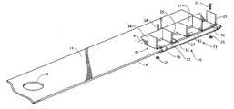
- FIG. 1 is a perspective view of a mower blade assembly in a preferred form of the invention.
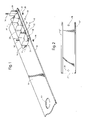
- FIG. 2 is a top view of the bottom blade of the mower blade assembly of FIG. 1 .
- FIG. 3 is a top view of the blade bar of the mower blade assembly of FIG. 1 .
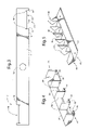
- FIG. 4 is a perspective view of the top blade of the mower blade assembly of FIG. 1 .
- FIG. 5 is a perspective view of a top blade in another preferred form of the invention.
- the mower blade assembly 10 includes an elongated blade bar 11 having a central mounting hole 12 , configured to receive the rotating axis of a lawn mower engine, and two oppositely disposed cutting ends 13 .
- Each cutting end 13 has a leading edge 14 and an elongated notch 16 extending inwardly from the leading edge 14 .
- the leading edges 14 are oriented forwardly with respect to the direction of blade movement during rotation.
- Each notch 16 in the preferred embodiment is defined by two side walls 17 and a rear wall 18 , as best shown in FIG. 3 .
- the blade bar 11 also has two pairs of blade mounting holes 19 adjacent each notch 16 .
- the mower blade assembly 10 also includes a pair of removable bottom blades 22 and a pair of removable top blades 23 .
- the bottom blades 22 and top blades 23 are mounted to the blade bar 11 adjacent the notch 16 through two pairs of bolts 24 and mating self-locking nuts 25 .
- the bottom blade 22 is elongated with two oppositely disposed serrated cutting edges 27 and two mounting holes 28 .
- the bottom blade 22 is symmetrical with respect to its longitudinal length so that either one of the two cutting edges 27 may be oriented forward of the blade bar leading edge 14 and thereby be utilized for cutting purposes.
- the top blade 23 has a forward portion 31 at least partially overlying the blade bar 11 .
- Each forward portion 31 includes a series of generally horizontal cutting blades or blade segments 32 with serrated cutting edges 33 , a series of generally vertical mulching blades 34 with serrated cutting edges 35 , and a pair of mounting holes 36 .
- the cutting edges 33 of the cutting blades 32 are mutually aligned with each other and positioned slightly forward of the notch rear wall 18 .
- the top blade 23 also has an elongated rear portion 37 that is oriented at an angle A with respect to the cutting blades 32 and blade bar 11 .
- the angle of the rear portion 37 creates or defines an airfoil deflector which increases the vacuum effect of the rotating blades.
- the top and bottom blades 23 and 22 are made of a hardened metal and may be coated in whole or in part, especially along the cutting edges, with a titanium coating to enhance the edge holding capabilities of the blades.
- top blade 23 is positioned on top of the blade bar 11 and mounting bolts 24 are passed through respective mounting holes 36 and 19 .
- the bottom blade 22 is then coupled to the blade bar 11 by similarly passing the mounting bolts 24 through its mounting holes 28 .
- Locking nuts 25 are then fastened to the mounting bolts 24 to lock the positions of the top and bottom blades to the blade bar.
- the rotation of the blade assembly causes the bottom blade cutting edge 27 and the top blade cutting edges 33 to cut the grass blades. These freshly severed grass blades then impact the mulching blades cutting edges 35 , whereby they are chopped into smaller grass segments or clippings.
- the multiple impacting of the bottom blades 22 and top blade cutting blades 32 and mulching blades 34 creates a grass clipping with a very small length, i.e., they create a finely chopped grass mulch. It is believed that the airfoil deflector maintains the grass clippings in suspension above the grass for a longer period of time, thereby allowing more impacts with the cutting edges and a resulting finer sized grass clipping.
- the bottom blade may be removed and reoriented so that its second cutting edge 27 is positioned to cut the underlying grass.
- This reversing of the bottom blade enables it to be used twice as long before having to be manually sharpened.
- the rotation of the blade assembly causes the bottom blade cutting edge 27 and the top blade cutting edges 33 to cut the grass blades.
- These freshly severed grass blades then impact the mulching blades cutting edges 35 , whereby they are chopped into smaller grass segments or clippings.
- the multiple impacting of the grass blades creates a grass clipping with a very small length.
- top blade 41 in another preferred form of the invention.
- the top blade 41 has a continuous serrated cutting edge 42 .
- the mulching blades 43 are positioned upon the angled rear portion 44 which forms the airfoil deflector.
- Generally triangular notches 45 terminating with cleaning holes 46 extend from the trailing edge. The cleaning holes 46 allow air to flow therethrough preventing the buildup of grass debris.
- the present invention is not limited to such.
- the term vertical is intended to reference an upward direction and as used herein is not intended to represent a direction exactly perpendicular to a horizontal reference as the mulching blades may be leaned to one side or the cutting edge angled with respect to the vertical.
- the number of mulching blades may vary and are not limited to the number shown in the preferred embodiments.
- the notches in the blade bar may extend to the end of the blade bar.
- the term notch is not intended to be limited to a space defined on three sides and may includes a step or other recess within the blade bar.
- the top and bottom blades may be mounted to the blade bar in any other conventionally known fashion, such as with tongue and groove fasteners, screws, clamps, catches, pins or other similar devices.
Landscapes
- Life Sciences & Earth Sciences (AREA)
- Environmental Sciences (AREA)
- Harvester Elements (AREA)
Abstract
A mower blade assembly (10) is disclosed which includes an elongated blade bar (11) having two oppositely disposed cutting ends (13). A pair of removable bottom blades (22) and a pair of removable top blades (23) are removably mounted to the blade bar. The bottom blade has two oppositely disposed serrated cutting edges (27) so that either of the two cutting edges may be utilized for cutting purposes. Each top blade has a forward portion (31) which includes a series of blade segments (32) with serrated cutting edges (33) and a series of mulching blades (34) with serrated cutting edges (35). The top blade also has an elongated rear portion (37) that is oriented at an angle with respect to the cutting blades and blade bar. The angle of the rear portion creates or defines an airfoil deflector which increases the vacuum effect of the rotating blades.
Description
- This invention relates to lawnmower blades, and specifically to rotary lawnmower blade assemblies.
- Rotary lawnmowers utilize a blade that is rotated about a central axis by a motor. The blade includes two oppositely disposed leading edges which cut the grass over which the lawnmower passes. These grass clippings are oftentimes collected in a removable bag so that the clippings may be gathered and disposed.
- The mower operator however may opt to leave the grass clippings on the lawn for mulch with subsequent decomposition for fertilization and a reduction in water needs for the lawn. When grass clippings are left on the lawn it is desired to have the clippings cut into the smallest pieces possible so that they do not rest upon the freshly cut grass, this is referred to as mulching the grass.
- Accordingly, it is seen that a need for a lawnmower blade which may reduce the size of grass clipping. It thus is to the provision of such that the present invention is primarily directed.
- In a preferred form of the invention, a mower blade assembly comprises a blade bar having a central engine mounting hole and two oppositely disposed cutting ends having a leading edge. The blade assembly has a pair of top cutting blades removably mounted to the blade bar. Each top cutting blade is mounted to one cutting end of the blade bar and has a first portion overlying the blade bar and a second portion angled with respect to the blade bar to create an airfoil deflector. The first portion has an elongated cutting edge.
- In another preferred form of the invention, a mower blade assembly comprises a blade bar having a central engine mounting hole and two oppositely disposed cutting ends having a leading edge. The blade assembly also has a pair of bottom cutting blades with each bottom cutting blade being removably mounted to one cutting end of the blade bar. Each bottom cutting blade also has two oppositely disposed elongated cutting edges. With this construction, either cutting edge of the bottom cutting blade may be positioned forwardly with respect to blade movement, and when one cutting edge becomes dull the position of the bottom cutting blade may be removed and remounted so that the other cutting edge is positioned forwardly with respect to blade movement.
- In another preferred form of the invention, a mower blade assembly comprises a blade bar having a central engine mounting hole and two oppositely disposed cutting ends having a leading edge. The blade assembly also has a pair of bottom cutting blades removably mounted to the blade bar and has an elongated cutting edge. Each bottom cutting blade is mounted to one cutting end of the blade bar. The blade assembly also includes a pair of top cutting blades removably mounted to the blade bar and having an elongated cutting edge. Each top cutting blade is mounted to one cutting end of the blade bar.
-
FIG. 1 is a perspective view of a mower blade assembly in a preferred form of the invention. -
FIG. 2 is a top view of the bottom blade of the mower blade assembly ofFIG. 1 . -
FIG. 3 is a top view of the blade bar of the mower blade assembly ofFIG. 1 . -
FIG. 4 is a perspective view of the top blade of the mower blade assembly ofFIG. 1 . -
FIG. 5 is a perspective view of a top blade in another preferred form of the invention. - With reference next to the drawings, there is shown an lawn
mower blade assembly 10 in a preferred form of the invention. Themower blade assembly 10 includes anelongated blade bar 11 having acentral mounting hole 12, configured to receive the rotating axis of a lawn mower engine, and two oppositely disposedcutting ends 13. Eachcutting end 13 has a leadingedge 14 and anelongated notch 16 extending inwardly from the leadingedge 14. The leadingedges 14 are oriented forwardly with respect to the direction of blade movement during rotation. Eachnotch 16 in the preferred embodiment is defined by twoside walls 17 and arear wall 18, as best shown inFIG. 3 . Theblade bar 11 also has two pairs ofblade mounting holes 19 adjacent eachnotch 16. - The
mower blade assembly 10 also includes a pair ofremovable bottom blades 22 and a pair of removabletop blades 23. Thebottom blades 22 andtop blades 23 are mounted to theblade bar 11 adjacent thenotch 16 through two pairs ofbolts 24 and mating self-locking nuts 25. - With reference next to
FIG. 2 , thebottom blade 22 is elongated with two oppositely disposedserrated cutting edges 27 and twomounting holes 28. Thebottom blade 22 is symmetrical with respect to its longitudinal length so that either one of the twocutting edges 27 may be oriented forward of the bladebar leading edge 14 and thereby be utilized for cutting purposes. - With reference next to
FIG. 4 , thetop blade 23 has aforward portion 31 at least partially overlying theblade bar 11. Eachforward portion 31 includes a series of generally horizontal cutting blades orblade segments 32 withserrated cutting edges 33, a series of generallyvertical mulching blades 34 withserrated cutting edges 35, and a pair ofmounting holes 36. Thecutting edges 33 of thecutting blades 32 are mutually aligned with each other and positioned slightly forward of the notchrear wall 18. - The
top blade 23 also has an elongatedrear portion 37 that is oriented at an angle A with respect to thecutting blades 32 andblade bar 11. The angle of therear portion 37 creates or defines an airfoil deflector which increases the vacuum effect of the rotating blades. The top andbottom blades - In use, the
top blade 23 is positioned on top of theblade bar 11 and mountingbolts 24 are passed throughrespective mounting holes bottom blade 22 is then coupled to theblade bar 11 by similarly passing themounting bolts 24 through itsmounting holes 28.Locking nuts 25 are then fastened to themounting bolts 24 to lock the positions of the top and bottom blades to the blade bar. - The rotation of the blade assembly causes the bottom
blade cutting edge 27 and the topblade cutting edges 33 to cut the grass blades. These freshly severed grass blades then impact the mulchingblades cutting edges 35, whereby they are chopped into smaller grass segments or clippings. The multiple impacting of thebottom blades 22 and topblade cutting blades 32 and mulchingblades 34 creates a grass clipping with a very small length, i.e., they create a finely chopped grass mulch. It is believed that the airfoil deflector maintains the grass clippings in suspension above the grass for a longer period of time, thereby allowing more impacts with the cutting edges and a resulting finer sized grass clipping. - It should be noted that if the forwardly positioned
cutting edge 27 of the bottom blade becomes dull, the bottom blade may be removed and reoriented so that itssecond cutting edge 27 is positioned to cut the underlying grass. This reversing of the bottom blade enables it to be used twice as long before having to be manually sharpened. The rotation of the blade assembly causes the bottomblade cutting edge 27 and the topblade cutting edges 33 to cut the grass blades. These freshly severed grass blades then impact the mulchingblades cutting edges 35, whereby they are chopped into smaller grass segments or clippings. The multiple impacting of the grass blades creates a grass clipping with a very small length. - With reference next to
FIG. 5 , there is shown atop blade 41 in another preferred form of the invention. Here, thetop blade 41 has a continuousserrated cutting edge 42. Furthermore, the mulching blades 43 are positioned upon the angledrear portion 44 which forms the airfoil deflector. Generallytriangular notches 45 terminating withcleaning holes 46 extend from the trailing edge. Thecleaning holes 46 allow air to flow therethrough preventing the buildup of grass debris. - It should be understood that even though the mulching blades have been shown with their cutting edges in a generally vertical orientation, the present invention is not limited to such. As such, the term vertical is intended to reference an upward direction and as used herein is not intended to represent a direction exactly perpendicular to a horizontal reference as the mulching blades may be leaned to one side or the cutting edge angled with respect to the vertical. It should also be understood that the number of mulching blades may vary and are not limited to the number shown in the preferred embodiments.
- It should be understood that the notches in the blade bar may extend to the end of the blade bar. As such, the term notch is not intended to be limited to a space defined on three sides and may includes a step or other recess within the blade bar. It should also be understood that the top and bottom blades may be mounted to the blade bar in any other conventionally known fashion, such as with tongue and groove fasteners, screws, clamps, catches, pins or other similar devices.
- It thus is seen that a lawn mower blade assembly is now provided that provides superior mulching capabilities. It should be understood that many modifications may be made to the specific preferred embodiment described herein, in addition to those specifically recited, without departure from the spirit and scope of the invention as described by the following claims.
Claims (35)
1. A mower blade assembly comprising,
a blade bar having two oppositely disposed cutting ends having a leading edge, and
a pair of top cutting blades removably mounted to said blade bar, each top cutting blade being mounted to one said cutting end of said blade bar and having a first portion at least partially overlying said blade bar and a second portion angled with respect to said blade bar to create an airfoil deflector, said first portion having an elongated cutting edge.
2. The mower blade assembly of claim 1 wherein each said top cutting blade also includes a plurality of mulching blades extending upwardly with respect to said blade bar.
3. The mower blade assembly of claim 2 wherein said plurality of mulching blades extend from said first portion.
4. The mower blade assembly of claim 2 wherein said plurality of mulching blades extend from said second portion.
5. The mower blade assembly of claim 1 further comprising a pair of bottom cutting blades, each bottom cutting blade being removably mounted to one cutting end of said blade bar and having an elongated cutting edge.
6. The mower blade assembly of claim 5 wherein said bottom cutting blade has two oppositely disposed elongated cutting edges.
7. The mower blade assembly of claim 5 wherein each cutting edge of said bottom cutting blade is positioned ahead of said cutting edge of said upper cutting blade, with respect to the direction of blade movement.
8. The mower blade assembly of claim 1 wherein at least said cutting edge of said top cutting blade is coated with titanium.
9. The mower blade assembly of claim 5 wherein at least said cutting edge of said bottom cutting blade is coated with titanium.
10. The mower blade assembly of claim 1 wherein each said blade bar cutting end include a notch and wherein each said top blade cutting edge is positioned above a respective said notch.
11. The mower blade assembly of claim 4 further comprising rear notches extending into said second portion.
12. The mower blade assembly of claim 11 further comprising a cleaning hole adjacent each rear notch.
13. A mower blade assembly comprising,
a blade bar having two oppositely disposed cutting ends having a leading edge, and
a pair of bottom cutting blades, each bottom cutting blade being removably mounted to one said cutting end of said blade bar, each bottom cutting blade also having two oppositely disposed elongated cutting edges,
whereby either cutting edge of the bottom cutting blade may be positioned forwardly with respect to blade movement, and when one cutting edge becomes dull the position of the bottom cutting blade may be removed and remounted so that the other cutting edge is positioned forwardly with respect to blade movement.
14. The mower blade assembly of claim 13 further comprising a pair of top cutting blades removably mounted to said blade bar and having an elongated cutting edge, each top cutting blade being mounted to one said cutting end of said blade bar.
15. The mower blade assembly of claim 14 wherein each said top cutting blade has a first portion overlying said blade bar and a second portion angled with respect to said blade bar to create an airfoil deflector, said first portion having an elongated cutting edge.
16. The mower blade assembly of claim 15 wherein each said top cutting blade also includes a plurality of mulching blades extending upwardly with respect to said blade bar.
17. The mower blade assembly of claim 16 wherein said plurality of mulching blades extend from said first portion.
18. The mower blade assembly of claim 16 wherein said plurality of mulching blades extend from said second portion.
19. The mower blade assembly of claim 14 wherein each cutting edge of said bottom cutting blade is positioned ahead of said cutting edge of said upper cutting blade, with respect to the direction of blade movement.
20. The mower blade assembly of claim 14 wherein at least said cutting edge of said top cutting blade is coated with titanium.
21. The mower blade assembly of claim 13 wherein at least said cutting edges of said bottom cutting blades are is coated with titanium.
22. The mower blade assembly of claim 14 wherein each said blade bar cutting end include a notch and wherein each said top blade cutting edge is positioned above a respective said notch.
23. The mower blade assembly of claim 18 further comprising rear notches extending into said second portion.
24. The mower blade assembly of claim 23 further comprising a cleaning hole adjacent each rear notch.
25. A mower blade assembly comprising,
a blade bar having two oppositely disposed cutting ends having a leading edge;
a pair of bottom cutting blades removably mounted to said blade bar and having an elongated cutting edge, each bottom cutting blade being mounted to one said cutting end of said blade bar, and
a pair of top cutting blades removably mounted to said blade bar and having an elongated cutting edge, each top cutting blade being mounted to one said cutting end of said blade bar.
26. The mower blade assembly of claim 25 wherein each bottom cutting blade has two oppositely disposed elongated cutting edges.
27. The mower blade assembly of claim 25 wherein each said top cutting blade has a first portion overlying said blade bar and a second portion angled with respect to said blade bar to create an airfoil deflector, said first portion having an elongated cutting edge.
28. The mower blade assembly of claim 25 wherein each said top cutting blade also includes a plurality of mulching blades extending upwardly with respect to said blade bar.
29. The mower blade assembly of claim 25 wherein each said top cutting blade has a first portion overlying said blade bar, a second portion angled with respect to said blade bar to create an airfoil deflector, and a plurality of mulching blades extending from said first portion.
30. The mower blade assembly of claim 25 wherein each said top cutting blade has a first portion overlying said blade bar, a second portion angled with respect to said blade bar to create an airfoil deflector, and a plurality of mulching blades extending from said second portion.
31. The mower blade assembly of claim 25 wherein each cutting edge of said bottom cutting blade is positioned ahead of said cutting edge of said upper cutting blade, with respect to the direction of blade movement.
32. The mower blade assembly of claim 25 wherein at least said cutting edge of said top cutting blade is coated with titanium.
33. The mower blade assembly of claim 25 wherein at least said cutting edges of said bottom cutting blades are is coated with titanium.
34. The mower blade assembly of claim 25 wherein each said blade bar cutting end include a notch and wherein each said top blade cutting edge is positioned above a respective said notch.
35. The mower blade assembly of claim 25 wherein said top blade is comprises of a plurality of spaced apart blade segments and said blade segments include said top blade cutting edge.
Priority Applications (7)
| Application Number | Priority Date | Filing Date | Title |
|---|---|---|---|
| US11/543,571 US7730708B2 (en) | 2006-10-05 | 2006-10-05 | Mower blade assembly |
| PCT/US2007/080155 WO2008045720A2 (en) | 2006-10-05 | 2007-10-02 | Mower blade assembly |
| CNA2007800374686A CN101534631A (en) | 2006-10-05 | 2007-10-02 | Mower blade assembly |
| MX2009003591A MX2009003591A (en) | 2006-10-05 | 2007-10-02 | Mower blade assembly. |
| AU2007307945A AU2007307945A1 (en) | 2006-10-05 | 2007-10-02 | Mower blade assembly |
| CA002665137A CA2665137A1 (en) | 2006-10-05 | 2007-10-02 | Mower blade assembly |
| EP07843650A EP2073622A2 (en) | 2006-10-05 | 2007-10-02 | Mower blade assembly |
Applications Claiming Priority (1)
| Application Number | Priority Date | Filing Date | Title |
|---|---|---|---|
| US11/543,571 US7730708B2 (en) | 2006-10-05 | 2006-10-05 | Mower blade assembly |
Publications (2)
| Publication Number | Publication Date |
|---|---|
| US20080098706A1 true US20080098706A1 (en) | 2008-05-01 |
| US7730708B2 US7730708B2 (en) | 2010-06-08 |
Family
ID=39283987
Family Applications (1)
| Application Number | Title | Priority Date | Filing Date |
|---|---|---|---|
| US11/543,571 Expired - Fee Related US7730708B2 (en) | 2006-10-05 | 2006-10-05 | Mower blade assembly |
Country Status (7)
| Country | Link |
|---|---|
| US (1) | US7730708B2 (en) |
| EP (1) | EP2073622A2 (en) |
| CN (1) | CN101534631A (en) |
| AU (1) | AU2007307945A1 (en) |
| CA (1) | CA2665137A1 (en) |
| MX (1) | MX2009003591A (en) |
| WO (1) | WO2008045720A2 (en) |
Cited By (3)
| Publication number | Priority date | Publication date | Assignee | Title |
|---|---|---|---|---|
| US20120198807A1 (en) * | 2011-02-04 | 2012-08-09 | Blount, Inc. | Blade with debris disbursing air lift |
| EP3545741A1 (en) * | 2018-03-29 | 2019-10-02 | Georg Berndl | Mulching blade for a mowing apparatus |
| EP3895516A1 (en) * | 2020-04-16 | 2021-10-20 | Nanjing Chervon Industry Co., Ltd. | Lawn mower |
Families Citing this family (7)
| Publication number | Priority date | Publication date | Assignee | Title |
|---|---|---|---|---|
| AU2012316766B2 (en) | 2011-09-29 | 2015-05-28 | Husqvarna Ab | Quick-change blade system |
| US20130199148A1 (en) * | 2012-02-08 | 2013-08-08 | Felix A. Goudeau, JR. | Cutting Blade Method and Apparatus |
| US9844176B2 (en) * | 2012-10-22 | 2017-12-19 | Fournier And Grande Trust | Weed trimmer extension device |
| USD755858S1 (en) * | 2015-05-15 | 2016-05-10 | Sean C. Brown | Blade assembly |
| JP6147881B1 (en) * | 2016-02-29 | 2017-06-14 | 本田技研工業株式会社 | Lawn mower |
| FR3078605B1 (en) * | 2018-09-05 | 2021-04-16 | Francois Chateau | MOWER BLADE EQUIPPED WITH A TWO-BLADE PERPENDICULAR DEVICE CUT PERFECTLY THE GRASS IN ONE TIME |
| EP3821692B1 (en) | 2018-09-27 | 2024-07-31 | Nanjing Chervon Industry Co., Ltd. | Lawn mower |
Citations (22)
| Publication number | Priority date | Publication date | Assignee | Title |
|---|---|---|---|---|
| US2547540A (en) * | 1946-03-14 | 1951-04-03 | Wiley T Roberts | Power mower |
| US2697322A (en) * | 1949-11-10 | 1954-12-21 | Watrous Corp | Cutter member for rotating disk type lawn mowers |
| US2764865A (en) * | 1953-12-21 | 1956-10-02 | Pollard John Mccollum | Blade for rotary mower |
| US2815631A (en) * | 1954-09-01 | 1957-12-10 | John Deere Plow Company | Rotary mower |
| US2837887A (en) * | 1957-05-03 | 1958-06-10 | Lord Mfg Co | Rotary lawn mower blade |
| US2869311A (en) * | 1956-11-14 | 1959-01-20 | Frontier Dev Company | Blade for rotary lawn mower |
| US3162990A (en) * | 1963-08-01 | 1964-12-29 | Harry R Cook | Safety-type, rotary vegetation cutting blade |
| US3538692A (en) * | 1968-03-19 | 1970-11-10 | George Cope | Grass mowing and mulching device |
| US3762138A (en) * | 1972-06-15 | 1973-10-02 | R Michael | Mower blade |
| US3769784A (en) * | 1972-02-24 | 1973-11-06 | S Jones | Rotary mower blades |
| US3998037A (en) * | 1975-12-18 | 1976-12-21 | Deans John N | Means for mulching leaves and the like |
| US4189903A (en) * | 1978-06-23 | 1980-02-26 | Mcdonough Power Equipment, Division Of Fuqua Industries, Inc. | Rotary lawn mower with removable mulching attachment |
| US4297831A (en) * | 1980-01-29 | 1981-11-03 | Black & Decker Inc. | Cutting blade for a rotary lawnmower |
| US4429518A (en) * | 1981-01-14 | 1984-02-07 | Luisa Fedeli | Blade structure, particularly for rotating grass shaving machines |
| US4995228A (en) * | 1990-04-30 | 1991-02-26 | Hladik Jr Joseph C | Cutting blade for rotary cutting machinery |
| US5199251A (en) * | 1991-12-19 | 1993-04-06 | Snapper Power Equipment Division Of Fuqua Industries, Inc. | Mulching blade including multiple cutting edges |
| US5233820A (en) * | 1992-12-18 | 1993-08-10 | Willsie Raymond W | Lawnmower blade |
| US5291725A (en) * | 1991-12-24 | 1994-03-08 | Meinerding Wesley C | Rotary mower blade |
| US5673545A (en) * | 1995-08-30 | 1997-10-07 | Deere & Company | Shredding attachment for rotary cutter |
| US20030209000A1 (en) * | 2002-05-08 | 2003-11-13 | Mannon N. Kevin | Mower blade |
| US20030221404A1 (en) * | 2002-03-06 | 2003-12-04 | Snapper, Inc. | Lawn mower with improved blade and blade housing |
| US20060168933A1 (en) * | 2005-02-01 | 2006-08-03 | Hill Robert G Jr | Blade for rotary cutting machine |
Family Cites Families (1)
| Publication number | Priority date | Publication date | Assignee | Title |
|---|---|---|---|---|
| JPS55144937A (en) * | 1979-04-24 | 1980-11-12 | Hitachi Metals Ltd | Doubly coated cutting tool |
-
2006
- 2006-10-05 US US11/543,571 patent/US7730708B2/en not_active Expired - Fee Related
-
2007
- 2007-10-02 CA CA002665137A patent/CA2665137A1/en not_active Abandoned
- 2007-10-02 CN CNA2007800374686A patent/CN101534631A/en active Pending
- 2007-10-02 MX MX2009003591A patent/MX2009003591A/en not_active Application Discontinuation
- 2007-10-02 AU AU2007307945A patent/AU2007307945A1/en not_active Abandoned
- 2007-10-02 WO PCT/US2007/080155 patent/WO2008045720A2/en not_active Ceased
- 2007-10-02 EP EP07843650A patent/EP2073622A2/en not_active Withdrawn
Patent Citations (24)
| Publication number | Priority date | Publication date | Assignee | Title |
|---|---|---|---|---|
| US2547540A (en) * | 1946-03-14 | 1951-04-03 | Wiley T Roberts | Power mower |
| US2697322A (en) * | 1949-11-10 | 1954-12-21 | Watrous Corp | Cutter member for rotating disk type lawn mowers |
| US2764865A (en) * | 1953-12-21 | 1956-10-02 | Pollard John Mccollum | Blade for rotary mower |
| US2815631A (en) * | 1954-09-01 | 1957-12-10 | John Deere Plow Company | Rotary mower |
| US2869311A (en) * | 1956-11-14 | 1959-01-20 | Frontier Dev Company | Blade for rotary lawn mower |
| US2837887A (en) * | 1957-05-03 | 1958-06-10 | Lord Mfg Co | Rotary lawn mower blade |
| US3162990A (en) * | 1963-08-01 | 1964-12-29 | Harry R Cook | Safety-type, rotary vegetation cutting blade |
| US3538692A (en) * | 1968-03-19 | 1970-11-10 | George Cope | Grass mowing and mulching device |
| US3769784A (en) * | 1972-02-24 | 1973-11-06 | S Jones | Rotary mower blades |
| US3762138A (en) * | 1972-06-15 | 1973-10-02 | R Michael | Mower blade |
| US3998037A (en) * | 1975-12-18 | 1976-12-21 | Deans John N | Means for mulching leaves and the like |
| US4189903A (en) * | 1978-06-23 | 1980-02-26 | Mcdonough Power Equipment, Division Of Fuqua Industries, Inc. | Rotary lawn mower with removable mulching attachment |
| US4297831A (en) * | 1980-01-29 | 1981-11-03 | Black & Decker Inc. | Cutting blade for a rotary lawnmower |
| US4429518A (en) * | 1981-01-14 | 1984-02-07 | Luisa Fedeli | Blade structure, particularly for rotating grass shaving machines |
| US4995228A (en) * | 1990-04-30 | 1991-02-26 | Hladik Jr Joseph C | Cutting blade for rotary cutting machinery |
| US5199251A (en) * | 1991-12-19 | 1993-04-06 | Snapper Power Equipment Division Of Fuqua Industries, Inc. | Mulching blade including multiple cutting edges |
| US5291725A (en) * | 1991-12-24 | 1994-03-08 | Meinerding Wesley C | Rotary mower blade |
| US5233820A (en) * | 1992-12-18 | 1993-08-10 | Willsie Raymond W | Lawnmower blade |
| US5673545A (en) * | 1995-08-30 | 1997-10-07 | Deere & Company | Shredding attachment for rotary cutter |
| US20030221404A1 (en) * | 2002-03-06 | 2003-12-04 | Snapper, Inc. | Lawn mower with improved blade and blade housing |
| US6848245B2 (en) * | 2002-03-06 | 2005-02-01 | Snapper, Inc. | Lawn mower with improved blade and blade housing |
| US20030209000A1 (en) * | 2002-05-08 | 2003-11-13 | Mannon N. Kevin | Mower blade |
| US6675569B2 (en) * | 2002-05-08 | 2004-01-13 | Frederick Manufacturing Corporation | Mower blade |
| US20060168933A1 (en) * | 2005-02-01 | 2006-08-03 | Hill Robert G Jr | Blade for rotary cutting machine |
Cited By (4)
| Publication number | Priority date | Publication date | Assignee | Title |
|---|---|---|---|---|
| US20120198807A1 (en) * | 2011-02-04 | 2012-08-09 | Blount, Inc. | Blade with debris disbursing air lift |
| EP3545741A1 (en) * | 2018-03-29 | 2019-10-02 | Georg Berndl | Mulching blade for a mowing apparatus |
| EP3895516A1 (en) * | 2020-04-16 | 2021-10-20 | Nanjing Chervon Industry Co., Ltd. | Lawn mower |
| US11812690B2 (en) | 2020-04-16 | 2023-11-14 | Nanjing Chervon Industry Co., Ltd. | Lawn mower and blade assembly |
Also Published As
| Publication number | Publication date |
|---|---|
| CA2665137A1 (en) | 2008-04-17 |
| AU2007307945A1 (en) | 2008-04-17 |
| EP2073622A2 (en) | 2009-07-01 |
| MX2009003591A (en) | 2009-04-16 |
| WO2008045720A2 (en) | 2008-04-17 |
| US7730708B2 (en) | 2010-06-08 |
| WO2008045720A3 (en) | 2008-07-03 |
| CN101534631A (en) | 2009-09-16 |
Similar Documents
| Publication | Publication Date | Title |
|---|---|---|
| CA2665137A1 (en) | Mower blade assembly | |
| US5212938A (en) | Mulching mower with obround cutting chamber | |
| US5363635A (en) | Mulching mower with improved mulching blade | |
| DE112011105538B4 (en) | Cutting knife | |
| KR20100063740A (en) | Grass cutting blade for mowing machine and mowing machine | |
| US4995228A (en) | Cutting blade for rotary cutting machinery | |
| US20060162310A1 (en) | Mulcher blade | |
| EP1527668B1 (en) | Mower Deck and Mowing Machine | |
| US5233820A (en) | Lawnmower blade | |
| WO2006083806A2 (en) | Blade for rotary cutting machine | |
| US20150359171A1 (en) | Auxiliary mulching mower blade | |
| US7299612B2 (en) | Rotary mower blade | |
| US20110277438A1 (en) | Lawn Mower Blade | |
| US5345788A (en) | Grass cutter and leaf blower blade | |
| US20200077602A1 (en) | Retrofit blower deck and a method of using the same | |
| EP3503708A1 (en) | Corn harvester with tall corn attachment and associated methods | |
| EP0030568A1 (en) | Cutter for the trimming of hedges and shrubs or the like | |
| US20180064029A1 (en) | Cutting blades for rotary cutter | |
| US20180343797A1 (en) | Double disc counter rotation mulching mower assembly | |
| KR101369492B1 (en) | Blade for lawn mower cutter and cutter thereof | |
| EP3545741B1 (en) | Mulching blade for a mowing apparatus | |
| EP2111737B1 (en) | Knife bar and mowing device or mower | |
| US20040112028A1 (en) | Mulching lawn mower blade assembly with replaceable inserts | |
| US4435951A (en) | Gardening device | |
| DE102006058958A1 (en) | Replacement lawnmower blade comprises two sections which curve in opposite directions, sides of blade being concave in direction of rotation and leading edges of sharpened sections being furthest away from central mounting of blade |
Legal Events
| Date | Code | Title | Description |
|---|---|---|---|
| FEPP | Fee payment procedure |
Free format text: PATENT HOLDER CLAIMS MICRO ENTITY STATUS, ENTITY STATUS SET TO MICRO (ORIGINAL EVENT CODE: STOM); ENTITY STATUS OF PATENT OWNER: MICROENTITY |
|
| FPAY | Fee payment |
Year of fee payment: 4 |
|
| FEPP | Fee payment procedure |
Free format text: MAINTENANCE FEE REMINDER MAILED (ORIGINAL EVENT CODE: REM.) |
|
| LAPS | Lapse for failure to pay maintenance fees |
Free format text: PATENT EXPIRED FOR FAILURE TO PAY MAINTENANCE FEES (ORIGINAL EVENT CODE: EXP.) |
|
| STCH | Information on status: patent discontinuation |
Free format text: PATENT EXPIRED DUE TO NONPAYMENT OF MAINTENANCE FEES UNDER 37 CFR 1.362 |
|
| FP | Lapsed due to failure to pay maintenance fee |
Effective date: 20180608 |