US20080098578A1 - Scaffold clamp - Google Patents
Scaffold clamp Download PDFInfo
- Publication number
- US20080098578A1 US20080098578A1 US11/923,025 US92302507A US2008098578A1 US 20080098578 A1 US20080098578 A1 US 20080098578A1 US 92302507 A US92302507 A US 92302507A US 2008098578 A1 US2008098578 A1 US 2008098578A1
- Authority
- US
- United States
- Prior art keywords
- scaffold
- yoke part
- clamp
- pipes
- yoke
- Prior art date
- Legal status (The legal status is an assumption and is not a legal conclusion. Google has not performed a legal analysis and makes no representation as to the accuracy of the status listed.)
- Abandoned
Links
- 230000007246 mechanism Effects 0.000 claims abstract description 44
- 125000006850 spacer group Chemical group 0.000 claims description 30
- 239000000463 material Substances 0.000 claims description 4
- 229920003023 plastic Polymers 0.000 claims description 2
- 239000004033 plastic Substances 0.000 claims description 2
- 230000004048 modification Effects 0.000 description 2
- 238000012986 modification Methods 0.000 description 2
- 230000000717 retained effect Effects 0.000 description 2
- XAGFODPZIPBFFR-UHFFFAOYSA-N aluminium Chemical compound [Al] XAGFODPZIPBFFR-UHFFFAOYSA-N 0.000 description 1
- 229910052782 aluminium Inorganic materials 0.000 description 1
- 239000004411 aluminium Substances 0.000 description 1
- 230000000712 assembly Effects 0.000 description 1
- 238000000429 assembly Methods 0.000 description 1
- 230000006835 compression Effects 0.000 description 1
- 238000007906 compression Methods 0.000 description 1
- 238000010276 construction Methods 0.000 description 1
- 230000005484 gravity Effects 0.000 description 1
- 230000013011 mating Effects 0.000 description 1
Images


Classifications
-
- E—FIXED CONSTRUCTIONS
- E04—BUILDING
- E04G—SCAFFOLDING; FORMS; SHUTTERING; BUILDING IMPLEMENTS OR AIDS, OR THEIR USE; HANDLING BUILDING MATERIALS ON THE SITE; REPAIRING, BREAKING-UP OR OTHER WORK ON EXISTING BUILDINGS
- E04G7/00—Connections between parts of the scaffold
- E04G7/02—Connections between parts of the scaffold with separate coupling elements
- E04G7/06—Stiff scaffolding clamps for connecting scaffold members of common shape
- E04G7/08—Clamps for parallelly-arranged members
-
- F—MECHANICAL ENGINEERING; LIGHTING; HEATING; WEAPONS; BLASTING
- F16—ENGINEERING ELEMENTS AND UNITS; GENERAL MEASURES FOR PRODUCING AND MAINTAINING EFFECTIVE FUNCTIONING OF MACHINES OR INSTALLATIONS; THERMAL INSULATION IN GENERAL
- F16L—PIPES; JOINTS OR FITTINGS FOR PIPES; SUPPORTS FOR PIPES, CABLES OR PROTECTIVE TUBING; MEANS FOR THERMAL INSULATION IN GENERAL
- F16L3/00—Supports for pipes, cables or protective tubing, e.g. hangers, holders, clamps, cleats, clips, brackets
- F16L3/22—Supports for pipes, cables or protective tubing, e.g. hangers, holders, clamps, cleats, clips, brackets specially adapted for supporting a number of parallel pipes at intervals
- F16L3/237—Supports for pipes, cables or protective tubing, e.g. hangers, holders, clamps, cleats, clips, brackets specially adapted for supporting a number of parallel pipes at intervals for two pipes
-
- Y—GENERAL TAGGING OF NEW TECHNOLOGICAL DEVELOPMENTS; GENERAL TAGGING OF CROSS-SECTIONAL TECHNOLOGIES SPANNING OVER SEVERAL SECTIONS OF THE IPC; TECHNICAL SUBJECTS COVERED BY FORMER USPC CROSS-REFERENCE ART COLLECTIONS [XRACs] AND DIGESTS
- Y10—TECHNICAL SUBJECTS COVERED BY FORMER USPC
- Y10T—TECHNICAL SUBJECTS COVERED BY FORMER US CLASSIFICATION
- Y10T24/00—Buckles, buttons, clasps, etc.
- Y10T24/44—Clasp, clip, support-clamp, or required component thereof
- Y10T24/44017—Clasp, clip, support-clamp, or required component thereof with specific mounting means for attaching to rigid or semirigid supporting structure or structure-to-be-secured
Definitions
- This invention relates to a scaffold clamp for retaining two scaffold pipes together in adjacent proximity.
- scaffolds have been traditionally built to required widths across the face of a building, or other structure, by assembling a plurality of upright scaffold pipes and interconnecting those upright scaffold pipes by horizontally transversely extending scaffold pipes.
- a scaffold can be built to extend across the width of a building or other structure and can be assembled in interconnecting parts relating to the lengths of the horizontally transverse scaffold pipes by adding additional scaffold pipes across an already assembled scaffold.
- the whole assembly is a unitary assembly, and is not built up from discrete scaffold modules.
- the scaffold modules are provided in a knockdown form so that one side or face of the scaffold module is provided as a unitary structure, and two such sides or faces are interconnected by horizontally extending scaffold pipes using known scaffold pipe connectors.
- a complete scaffold module typically 2 m wide ⁇ 1 m deep ⁇ 2 m high is formed.
- a scaffold module can be built to any height by simply stacking multiples of these independent discrete modules one above the other.
- a scaffold clamp for retaining two scaffold pipes together in adjacent proximity, said clamp comprising a first yoke part for engaging with an external surface of one of the scaffold pipes, and a second yoke part for engaging with an external surface of the other of the scaffold pipes,
- each of the first yoke part and the second yoke parts being of lengths to extend to overlap past the sides of the respective two scaffold pipes
- first yoke part and the second yoke part at the other side of first yoke part and the second yoke part
- the scaffold clamp being such that the two scaffold pipes will be embraced within a space defined by the first yoke part and the second yoke part, and the stringer and the clamping mechanism, so that the clamping mechanism can be operated to relatively draw the first yoke part towards the second yoke part and to retain the two scaffold pipes together in adjacent proximity.
- the stringer part is connected with at least one of the first yoke part or second yoke part by a connection that permits relative swinging of the stringer part relative to the respective yoke part, and wherein, in use, an axis of swinging is generally parallel with a longitudinal central axis of a scaffold pipe to which the scaffold clamp is to be used with.
- the stringer part is connected with both the one yoke part and the second yoke part by respective connections that permit relative swinging of the stringer part relative to both yoke parts.
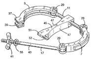
- FIG. 1 is a horizontal cross sectional view taken through two adjacent upright scaffold pipes that each are provided on independent scaffold modules.
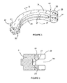
- FIG. 2 is an isometric view of a yoke part of the scaffold clamp shown in FIG. 1 .
- FIG. 3 is a vertical cross sectional view taken along section line 3 3 ′ of FIG. 2 .
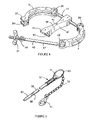
- FIG. 4 is a perspective view showing the scaffold clamp in a open condition and with a scaffold pipe spacer.
- FIG. 5 is a perspective view showing a locating pin which is used to co-operate with the scaffold clamp shown in FIG. 4 .
- FIG. 6 is an isometric view showing the spacer isolated from the scaffold clamp.
- FIG. 7 is a vertical cross sectional view taken along section line 7 7 ′ of FIG. 1 showing the scaffold clamp in position and showing the locating pin in position.
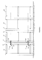
- FIG. 8 is a front elevational view showing how independent discrete scaffold modules are interconnected so that two scaffold pipes of adjacent modules are retained in adjacent proximity using the scaffold clamp, and
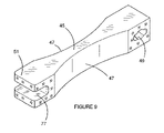
- FIG. 9 is an isometric view showing an alternative form of spacer for use with the scaffold clamp.
- Scaffold pipe 3 is an upright scaffold pipe of one scaffold module and scaffold pipe 5 is an upright pipe of the other scaffold module.
- the scaffold modules are shown in FIG. 8 and will be referred to later.
- Scaffold clamp 1 comprises a first yoke part 7 and a second yoke part 9 for engaging with external surfaces of the respective scaffold pipes 3 and 5 .
- the yoke parts 7 and 9 are made from cast aluminium.
- FIG. 1 clearly shows that the yoke parts 7 and 9 are of lengths to extend to overlap past the sides of the respective two scaffold pipes 3 and 5 .
- the first yoke part 7 and the second yoke part 9 are interconnected by a stringer part 11 .
- This stringer part 11 extends to connect with one side 13 of the first yoke part 7 , and one side 15 of the second yoke part 9 .
- a clamping mechanism 17 interconnects the first yoke part 7 and the second yoke part 9 at the other side 19 of the first yoke part, and the other side 21 of the second yoke part 9 .
- the scaffold clamp 1 is such that the two scaffold pipes 3 and 5 will be embraced within a space 23 defined by the first yoke part 7 and the second yoke part 9 , and the stringer 11 and the clamping mechanism 17 .
- the clamping mechanism 17 can then be operated to relatively draw the first yoke part 7 towards the second yoke part 9 and to retain the two scaffold pipes 3 and 5 together in adjacent proximity.
- FIG. 2 shows an isometric view of the second yoke part 9 .
- the second yoke part 9 has a generally rectangular transverse cross sectional shape as shown by FIG. 3 .
- the face 25 of the second yoke part 9 has a curved profile so that the external surface of a scaffold pipe 3 can nest therein.
- FIG. 3 clearly shows that the face 25 has a centrally positioned relief 27 so as to provide two exposed faces 25 that will engage with the outer surfaces of the scaffold pipe 3 and provide for good mating contact therewith.
- the second yoke part 9 has a head 29 at the one side 15 .
- the head 29 is generally cylindrical in shape and has a central cut-out part 31 for receipt of an end of the stringer part 11 .
- the head 29 also has a central bore 33 therethrough so that a hinge pin 35 can pass through the head 29 and through an opening in an end of the stringer part 11 to swing connect the second yoke part relative to the stringer 11 .
- the end of the stringer 11 may be suitably enlarged enabling it to locate within the head 29 and to receive the pin 35 .
- the other side 21 of the second yoke part 9 is provided with a generally rectangular block end 37 .
- the block end 37 has a generally horizontally extending passageway 39 therethrough.
- FIG. 2 shows that the passageway 39 is open at the extreme free end of the block end 37 .
- the first yoke part 7 has a similar construction to that of the second yoke part 9 except that the first yoke part 7 has two heads 29 —one being at one end 13 and the other at the other end 19 .
- Similar hinge pins 35 are provided through similar bores 33 to permit the stringer part 11 to be connected therewith, and to permit the clamping mechanism 17 to be connected therewith.
- the respective ends of the stringer part 11 and the clamping mechanism 17 are suitably shaped to fit within cut-out parts of the heads 29 and to receive the hinge pins 35 .
- the arrangement is such that the connections between the first yoke part 7 and the stringer part 11 , and the second yoke part 9 and the stringer part 11 is such that there can be relative swinging of the stringer part 11 relative to the respective yoke parts 7 and 9 .
- the axis of swinging is generally parallel with a longitudinal central axis of a scaffold pipe 3 or 5 to which the scaffold clamp is to be used with.
- FIG. 1 shows that the clamping mechanism 7 is connected with the first yoke part 7 , however, it could be connected with a swing connection to the second yoke part 9 .
- the head 29 shown on the other side 19 of the first yoke part 7 would be provided at the other side 21 of the second yoke part 9 .
- Block end 37 shown on the second yoke part 9 would then be provided on the first yoke part 7 at the other side 19 .
- FIG. 1 shows that the clamping mechanism 17 is a screw threaded operating clamping mechanism.
- a nut 41 is screw threaded onto an elongate arm part 43 that forms part of the clamping mechanism 17 .
- the arrangement is such that the arm part 43 can be swung about the hinge pin 35 to open and/or close the space 23 .
- the nut 31 can be rotated on the arm part 43 to screw threadably draw the first yoke part 7 towards the second yoke part 9 to hold the two scaffold parts 3 and 5 together in adjacent proximity.
- the lengths of the stringer part 11 and the arm part 43 are suitably chosen having regard to the diameters of the scaffold pipes 3 and 5 and the distance of spacing apart of the scaffold pipes 3 and 5 .
- FIG. 1 clearly shows that the axis of swinging of the clamping mechanism 17 about hinge pin 35 is generally parallel with the axis of swinging of the connection between the stringer part 11 and the first yoke part 7 or second yoke part 9 .
- each of the hinge pins 35 are aligned generally upright and vertical when in use.
- the horizontally extending passageway 39 acts to provide a socket for receipt of the arm part 43 of the clamping mechanism 17 .
- the nut 41 when the nut 41 is screw threadably rotated to move along the arm part 43 , the nut will apply a clamping pressure to the socket formed by the horizontally extending passageway 39 and permit a clamping force to be applied to draw the first yoke part 7 towards the second yoke part 9 .
- the scaffold clamp 1 is provided with a scaffold pipe spacer 45 .
- the scaffold pipe spacer 45 is formed from a compressible synthetic plastics material.
- the scaffold pipe spacer 45 may be formed of any suitable material, however, it is desirable to have a compressible material with limited compression characteristics.
- the scaffold pipe spacer 45 is provided to be placed between the two scaffold pipes 3 and 5 . Under such conditions, the spacer 45 will space the scaffold pipes 3 and 5 and permit compressive clamping to occur to the two pipes from the first yoke part 7 and the second yoke part 9 when the first yoke part 7 is relatively drawn towards the second yoke part 9 .
- FIG. 4 and FIG. 6 show that the scaffold pipe spacer 45 has the surfaces thereof that engage with the outer surfaces of the scaffold pipes 3 and 5 of a suitable curved profile to conform with the general curved profile of the external surfaces of the scaffold pipes 3 and 5 .
- FIG. 6 in particular shows that the scaffold pipe spacer 45 has a hole 49 so that the spacer 45 can be held to the scaffold clamp 1 by either the stringer part 11 passing through the hole 49 or by the arm of the clamping mechanism 17 passing through the hole 49 .
- the stringer part 11 passes through the hole 49 .
- the scaffold pipe spacer 45 can swing relative to the stringer part 11 so that it extends into the space 23 .
- the length of scaffold pipe spacer 45 is sufficient to span across the space 23 and to rest upon the arm 43 of the clamping mechanism 17 .
- the free end 51 of the scaffold pipe spacer 45 has an arcuate cut-out pipe 53 so that the free end 51 can rest over the top of the arm 43 .
- FIG. 4 clearly shows that the ends of the stringer part 11 are suitably shaped to fit within the heads 29 of the first yoke part 7 and second yoke part 9 and that the end of the clamping mechanism 17 that connects with the head 29 of the first yoke part 7 is also suitably shaped to locate therewith.
- FIG. 4 also shows a washer 55 to act as a suitable washer surface with the block end 37 during tightening of the nut 41 .
- the clamping mechanism 17 is swung so as to open the scaffold clamp 1 .
- the yoke parts 7 or 9 are also swung relative to the stringer part 11 so as to move them outwardly.
- the scaffold clamp 1 is then fitted about two adjacent scaffold pipes 3 and 5 and the first yoke part 7 and second yoke part 9 swung so that they move inwardly towards the two scaffold pipes 3 and 5 .
- the clamping mechanism 17 is then swung so that the arm 43 is received within the horizontally extending passageway 39 —socket—and so that the nut 41 can then be screw threadably moved along the arm 43 to relatively move the first yoke part 7 and second yoke part 9 together.
- Continued rotation of the nut 41 permits a compressive force to be applied such that the scaffold pipes 3 and 5 are tightly engaged with the first yoke part 7 , the spacer 45 , and the second yoke part 9 .
- FIG. 8 shows how independent discrete scaffold modules 57 can be interconnected using the scaffold clamp 1 .
- two adjacent scaffold modules 57 are brought into proximity so that upright scaffold pipes 3 and 5 are in adjacent proximity.
- One scaffold clamp 1 is fitted to an upper part of the two scaffold modules 57 and another scaffold clamp 1 is fitted to a lower part of two scaffold modules 57 . Whilst two scaffold clamps 1 have been shown other numbers of scaffold clamps 1 may be utilised.
- the scaffold clamps 1 are suitably fitted about the upright scaffold pipes 3 and 5 and the clamping mechanisms 17 are operated to relatively draw the first yoke parts 7 towards the second yoke parts 9 to retain the two scaffold pipes 3 and 5 together in adjacent proximity.
- the spacer acts to suitably space the two scaffold modules 57 and enables compressive forces to be applied by the clamping mechanism 17 to clampingly hold two scaffold modules 57 in adjacent proximity.
- the two scaffold pipes 3 and 5 can abut with each other to enable compressive clamping forces to be applied between them.
- the two scaffold modules 57 can abut with each other by contact being made between protruding parts of the two modules. These protruding parts may be parts of the modules that hold the various pipes of each of the respective modules in fixed relation to each other.
- the scaffold clamps permit enhanced functionality of scaffold build modules without the need for additional scaffold pipes, floor, and other bulky components.
- the scaffold clamps are relatively inexpensive compared to all of the additional bulky components, and therefore provide for greater possibilities in module size interconnected assemblies.
- a locating pin 59 that can be associated with the scaffold clamp 1 and useable to height locate the scaffold clamp 1 relative to the upright scaffold pipes 3 and 5 .
- the locating pin 59 therefore acts as a position locator by passing through pre-provided aligned apertures 61 (see FIGS. 7 and 8 ) that are provided laterally across each of the scaffold pipes 3 and 5 in aligned positions.
- the locating pin 59 can pass through the apertures 61 which will laterally vertically align the scaffold modules 57 and also act as a position support so that the scaffold clamps 1 can be rested thereabove and suitably operated to hold the scaffold pipes 3 and 5 together in adjacent proximity.
- the locating pin 59 is elongate and has a toggle nose end 63 which is swing pivoted thereto through pivot pin 65 .
- the opposite end of the locating pin 59 carries a coil spring 67 in close fitting engagement over the outer surface at that end.
- An ‘O’ ring 69 is fitted through a passageway 71 in the locating pin 59 .
- the coil spring 67 is held retained to the end of the locating pin 59 by the ring 69 .
- the locating pin 59 is passed through the pre-provided aligned apertures 61 in both of the scaffold pipes 3 and 5 so that the coil spring 67 is slightly compressed and so the toggle nose end 63 can be force swung downwardly thereby retaining the locating pin 59 fixed relative to the two scaffold pipes 3 and 5 .
- a suitable flexible connector 73 can connect from the ring 69 to a connecting head 75 .
- the connecting head 75 has an aperture therein through which the stringer part 11 can pass or through which the arm 43 of the clamping mechanism 17 can pass. In this way, the locating pin 59 can be held to the scaffold clamp 1 . This, in turn, prevents the locating pin 59 from becoming displaced from the scaffold clamp 1 such that it may inadvertently be lost and not utilised to correctly position the height where the scaffold clamp 1 is to embrace the scaffold pipes 3 and 5 .
- FIG. 9 there is shown an alternative form of scaffold pipe spacer 45 .
- the arm part 43 of the clamping mechanism 17 is arranged to fit within the passageway 77 .
- the scaffold clamp 1 may be used in the position up side down to that shown in FIG. 4 .
- the scaffold pipe spacer 45 will not fall away by gravity from the arm part 43 of the clamping mechanism 17 prior to the clamping forces being applied by the clamping mechanism 17 .
- FIG. 9 also shows that the hole 49 is made somewhat elliptical in shape so that the pipe spacer 45 can be moved backwards and forwards relative to the stringer part 11 across the space.
- a safety pin may be provided to pass through suitable openings in the block end 37 of the second yoke part 9 to hold the arm part 43 of the clamping mechanism 17 captive relative to the second yoke part 9 .
- This may provide an additional safety feature of captively retaining the arm part 43 within the horizontally extending passageway 39 .
- toggle operated clamping mechanisms or other known clamping mechanisms may be utilised with a similar result.
Landscapes
- Engineering & Computer Science (AREA)
- Architecture (AREA)
- Mechanical Engineering (AREA)
- Civil Engineering (AREA)
- Structural Engineering (AREA)
- General Engineering & Computer Science (AREA)
- Mutual Connection Of Rods And Tubes (AREA)
Abstract
A scaffold clamp 1 is provided for retaining two scaffold pipes 3 and 5 in close proximity. The scaffold clamp 1 comprises a first yoke part 7 for engaging with external surface of one of the scaffold pipes 3/5. A second yoke part 9 is provided for engaging with external surfaces of the other of the scaffold pipes 3/5. A stringer part 11 interconnects the first yoke part 7 and the second yoke part 9 at one side. A clamping mechanism 17 is provided for interconnecting the first yoke part 7 and the second yoke part 9 at the other side. The scaffold clamp is such that the two scaffold pipes 3/5 will be embraced within a space 23 defined by the first yoke part 7 and the second yoke part 9, and the stringer part 11 and the clamping mechanism 17, so there can be relative drawing of the first yoke part 7 towards the second yoke part 9 to retain the two scaffold pipes 3/5 in adjacent proximity.
Description
- This application is based on and claims the benefit of the filing dates of Australian application no. 2006906006 filed 27 Oct. 2006 and U.S. application No. 60/868,602 filed 5 Dec. 2006, the contents of which are incorporated herein in the entirety.
- This invention relates to a scaffold clamp for retaining two scaffold pipes together in adjacent proximity.
- Hitherto, scaffolds have been traditionally built to required widths across the face of a building, or other structure, by assembling a plurality of upright scaffold pipes and interconnecting those upright scaffold pipes by horizontally transversely extending scaffold pipes. In this way, a scaffold can be built to extend across the width of a building or other structure and can be assembled in interconnecting parts relating to the lengths of the horizontally transverse scaffold pipes by adding additional scaffold pipes across an already assembled scaffold. The whole assembly is a unitary assembly, and is not built up from discrete scaffold modules.
- In recent times, there have been physically independent and discrete scaffold modules produced. Typically, the scaffold modules are provided in a knockdown form so that one side or face of the scaffold module is provided as a unitary structure, and two such sides or faces are interconnected by horizontally extending scaffold pipes using known scaffold pipe connectors. In such case, a complete scaffold module typically 2 m wide×1 m deep×2 m high is formed. A scaffold module can be built to any height by simply stacking multiples of these independent discrete modules one above the other. Typically, there is a ferule socket and pin interconnection between adjacent height modules. When these individual discrete modules are utilised, interconnection between adjacent modules that extend across the width of a building or other structure has presented a problem, and generally, the independent modules that are spaced across the width of a building are not interconnected together, and stand independent of each other. This is not desirable. In some cases, independent modules have been interconnected by a bridge which is usually of several meters in length, but the bridge requires the use of additional scaffold pipes, floor, and other bulky components, and because of this is generally inconvenient and additionally requires these bulky components to be separately purchased or hired.
- Therefore, according to a first broad aspect of the present invention, there is provided a scaffold clamp for retaining two scaffold pipes together in adjacent proximity, said clamp comprising a first yoke part for engaging with an external surface of one of the scaffold pipes, and a second yoke part for engaging with an external surface of the other of the scaffold pipes,
- each of the first yoke part and the second yoke parts being of lengths to extend to overlap past the sides of the respective two scaffold pipes,
- a stringer part interconnecting the first yoke part and the second yoke part at one side of the first yoke part and at one side of the second yoke part,
- and a clamping mechanism for interconnecting the first yoke part and the second yoke part at the other side of first yoke part and the second yoke part,
- the scaffold clamp being such that the two scaffold pipes will be embraced within a space defined by the first yoke part and the second yoke part, and the stringer and the clamping mechanism, so that the clamping mechanism can be operated to relatively draw the first yoke part towards the second yoke part and to retain the two scaffold pipes together in adjacent proximity.
- In an example, the stringer part is connected with at least one of the first yoke part or second yoke part by a connection that permits relative swinging of the stringer part relative to the respective yoke part, and wherein, in use, an axis of swinging is generally parallel with a longitudinal central axis of a scaffold pipe to which the scaffold clamp is to be used with.
- In an example, the stringer part is connected with both the one yoke part and the second yoke part by respective connections that permit relative swinging of the stringer part relative to both yoke parts.
- In order that the invention can be more clearly ascertained, examples of embodiments will now be described with reference to the accompanying drawings wherein:
-
FIG. 1 is a horizontal cross sectional view taken through two adjacent upright scaffold pipes that each are provided on independent scaffold modules. -
FIG. 2 is an isometric view of a yoke part of the scaffold clamp shown inFIG. 1 . -
FIG. 3 is a vertical cross sectional view taken alongsection line 3 3′ ofFIG. 2 . -
FIG. 4 is a perspective view showing the scaffold clamp in a open condition and with a scaffold pipe spacer. -
FIG. 5 is a perspective view showing a locating pin which is used to co-operate with the scaffold clamp shown inFIG. 4 . -
FIG. 6 is an isometric view showing the spacer isolated from the scaffold clamp. -
FIG. 7 is a vertical cross sectional view taken alongsection line 7 7′ ofFIG. 1 showing the scaffold clamp in position and showing the locating pin in position. -
FIG. 8 is a front elevational view showing how independent discrete scaffold modules are interconnected so that two scaffold pipes of adjacent modules are retained in adjacent proximity using the scaffold clamp, and -
FIG. 9 is an isometric view showing an alternative form of spacer for use with the scaffold clamp. - Referring firstly to the example of the scaffold clamp shown in
FIGS. 1-4 , it can be seen that thescaffold clamp 1 retains twoscaffold pipes pipe 3 is an upright scaffold pipe of one scaffold module andscaffold pipe 5 is an upright pipe of the other scaffold module. The scaffold modules are shown inFIG. 8 and will be referred to later.Scaffold clamp 1 comprises afirst yoke part 7 and asecond yoke part 9 for engaging with external surfaces of therespective scaffold pipes yoke parts FIG. 1 clearly shows that theyoke parts scaffold pipes first yoke part 7 and thesecond yoke part 9 are interconnected by astringer part 11. Thisstringer part 11 extends to connect with oneside 13 of thefirst yoke part 7, and oneside 15 of thesecond yoke part 9. Aclamping mechanism 17 interconnects thefirst yoke part 7 and thesecond yoke part 9 at theother side 19 of the first yoke part, and theother side 21 of thesecond yoke part 9. Thescaffold clamp 1 is such that the twoscaffold pipes space 23 defined by thefirst yoke part 7 and thesecond yoke part 9, and thestringer 11 and theclamping mechanism 17. Theclamping mechanism 17 can then be operated to relatively draw thefirst yoke part 7 towards thesecond yoke part 9 and to retain the twoscaffold pipes -
FIG. 2 shows an isometric view of thesecond yoke part 9. Here, it can be seen that thesecond yoke part 9 has a generally rectangular transverse cross sectional shape as shown byFIG. 3 . Theface 25 of thesecond yoke part 9 has a curved profile so that the external surface of ascaffold pipe 3 can nest therein.FIG. 3 clearly shows that theface 25 has a centrally positionedrelief 27 so as to provide two exposedfaces 25 that will engage with the outer surfaces of thescaffold pipe 3 and provide for good mating contact therewith. Thesecond yoke part 9 has ahead 29 at the oneside 15. Thehead 29 is generally cylindrical in shape and has a central cut-outpart 31 for receipt of an end of thestringer part 11. Thehead 29 also has acentral bore 33 therethrough so that ahinge pin 35 can pass through thehead 29 and through an opening in an end of thestringer part 11 to swing connect the second yoke part relative to thestringer 11. The end of thestringer 11 may be suitably enlarged enabling it to locate within thehead 29 and to receive thepin 35. Theother side 21 of thesecond yoke part 9 is provided with a generallyrectangular block end 37. Theblock end 37 has a generally horizontally extendingpassageway 39 therethrough.FIG. 2 shows that thepassageway 39 is open at the extreme free end of theblock end 37. This is to enable theclamping mechanism 17 to be received therein and to permit opening and closing of the clamping mechanism during fitting and/or removal of the clamping mechanism from the twoscaffold pipes first yoke part 7 has a similar construction to that of thesecond yoke part 9 except that thefirst yoke part 7 has twoheads 29—one being at oneend 13 and the other at theother end 19.Similar hinge pins 35 are provided throughsimilar bores 33 to permit thestringer part 11 to be connected therewith, and to permit theclamping mechanism 17 to be connected therewith. The respective ends of thestringer part 11 and theclamping mechanism 17 are suitably shaped to fit within cut-out parts of theheads 29 and to receive thehinge pins 35. The arrangement is such that the connections between thefirst yoke part 7 and thestringer part 11, and thesecond yoke part 9 and thestringer part 11 is such that there can be relative swinging of thestringer part 11 relative to therespective yoke parts scaffold pipe stringer part 11 to only one of thefirst yoke part 7 orsecond yoke part 9. Preferably, there is a swinging connection between thestringer part 11 and each of thefirst yoke part 7 and thesecond yoke part 9 as shown inFIG. 1 . -
FIG. 1 shows that theclamping mechanism 7 is connected with thefirst yoke part 7, however, it could be connected with a swing connection to thesecond yoke part 9. In such a situation, thehead 29 shown on theother side 19 of thefirst yoke part 7 would be provided at theother side 21 of thesecond yoke part 9.Block end 37 shown on thesecond yoke part 9 would then be provided on thefirst yoke part 7 at theother side 19. -
FIG. 1 shows that theclamping mechanism 17 is a screw threaded operating clamping mechanism. Here, anut 41 is screw threaded onto anelongate arm part 43 that forms part of theclamping mechanism 17. The arrangement is such that thearm part 43 can be swung about thehinge pin 35 to open and/or close thespace 23. In the position shown inFIG. 1 , thenut 31 can be rotated on thearm part 43 to screw threadably draw thefirst yoke part 7 towards thesecond yoke part 9 to hold the twoscaffold parts stringer part 11 and thearm part 43 are suitably chosen having regard to the diameters of thescaffold pipes scaffold pipes -
FIG. 1 clearly shows that the axis of swinging of theclamping mechanism 17 abouthinge pin 35 is generally parallel with the axis of swinging of the connection between thestringer part 11 and thefirst yoke part 7 orsecond yoke part 9. In other words, each of the hinge pins 35 are aligned generally upright and vertical when in use. The horizontally extendingpassageway 39 acts to provide a socket for receipt of thearm part 43 of theclamping mechanism 17. Thus, when thenut 41 is screw threadably rotated to move along thearm part 43, the nut will apply a clamping pressure to the socket formed by the horizontally extendingpassageway 39 and permit a clamping force to be applied to draw thefirst yoke part 7 towards thesecond yoke part 9. - Referring now to
FIG. 4 , it can be seen that thescaffold clamp 1 is provided with ascaffold pipe spacer 45. Here, thescaffold pipe spacer 45 is formed from a compressible synthetic plastics material. Thescaffold pipe spacer 45 may be formed of any suitable material, however, it is desirable to have a compressible material with limited compression characteristics. Thescaffold pipe spacer 45 is provided to be placed between the twoscaffold pipes spacer 45 will space thescaffold pipes first yoke part 7 and thesecond yoke part 9 when thefirst yoke part 7 is relatively drawn towards thesecond yoke part 9.FIG. 4 andFIG. 6 show that thescaffold pipe spacer 45 has the surfaces thereof that engage with the outer surfaces of thescaffold pipes scaffold pipes -
FIG. 6 in particular shows that thescaffold pipe spacer 45 has ahole 49 so that thespacer 45 can be held to thescaffold clamp 1 by either thestringer part 11 passing through thehole 49 or by the arm of theclamping mechanism 17 passing through thehole 49. In the example shown, thestringer part 11 passes through thehole 49. In this case, thescaffold pipe spacer 45 can swing relative to thestringer part 11 so that it extends into thespace 23. The length ofscaffold pipe spacer 45 is sufficient to span across thespace 23 and to rest upon thearm 43 of theclamping mechanism 17. Thefree end 51 of thescaffold pipe spacer 45 has an arcuate cut-outpipe 53 so that thefree end 51 can rest over the top of thearm 43. -
FIG. 4 clearly shows that the ends of thestringer part 11 are suitably shaped to fit within theheads 29 of thefirst yoke part 7 andsecond yoke part 9 and that the end of theclamping mechanism 17 that connects with thehead 29 of thefirst yoke part 7 is also suitably shaped to locate therewith.FIG. 4 also shows awasher 55 to act as a suitable washer surface with theblock end 37 during tightening of thenut 41. - In use, the
clamping mechanism 17 is swung so as to open thescaffold clamp 1. Theyoke parts stringer part 11 so as to move them outwardly. Thescaffold clamp 1 is then fitted about twoadjacent scaffold pipes first yoke part 7 andsecond yoke part 9 swung so that they move inwardly towards the twoscaffold pipes clamping mechanism 17 is then swung so that thearm 43 is received within the horizontally extendingpassageway 39—socket—and so that thenut 41 can then be screw threadably moved along thearm 43 to relatively move thefirst yoke part 7 andsecond yoke part 9 together. Continued rotation of thenut 41 permits a compressive force to be applied such that thescaffold pipes first yoke part 7, thespacer 45, and thesecond yoke part 9. -
FIG. 8 shows how independentdiscrete scaffold modules 57 can be interconnected using thescaffold clamp 1. Here, twoadjacent scaffold modules 57 are brought into proximity so thatupright scaffold pipes scaffold clamp 1 is fitted to an upper part of the twoscaffold modules 57 and anotherscaffold clamp 1 is fitted to a lower part of twoscaffold modules 57. Whilst two scaffold clamps 1 have been shown other numbers of scaffold clamps 1 may be utilised. The scaffold clamps 1 are suitably fitted about theupright scaffold pipes mechanisms 17 are operated to relatively draw thefirst yoke parts 7 towards thesecond yoke parts 9 to retain the twoscaffold pipes scaffold clamp 1 includes ascaffold pipe spacer 45 then the spacer acts to suitably space the twoscaffold modules 57 and enables compressive forces to be applied by theclamping mechanism 17 to clampingly hold twoscaffold modules 57 in adjacent proximity. If thescaffold pipe spacers 45 are not provided, the twoscaffold pipes scaffold modules 57 can abut with each other by contact being made between protruding parts of the two modules. These protruding parts may be parts of the modules that hold the various pipes of each of the respective modules in fixed relation to each other.FIG. 8 shows a one dimensional spread of thescaffold modules 57, however, it should be appreciated that there may also be a two dimensional spread of the scaffold modules. Accordingly by utilizing a scaffold module of a size 1.8 m wide, by 0.75 m deep, by 1.4 m high as an example, it is possible by using three such modules to provide the following: -
-
- Plus One 1.8 m×0.7 mm×1.4 m Module
- Thus, the scaffold clamps permit enhanced functionality of scaffold build modules without the need for additional scaffold pipes, floor, and other bulky components. The scaffold clamps are relatively inexpensive compared to all of the additional bulky components, and therefore provide for greater possibilities in module size interconnected assemblies.
- Returning now to
FIG. 5 , there is shown a locatingpin 59 that can be associated with thescaffold clamp 1 and useable to height locate thescaffold clamp 1 relative to theupright scaffold pipes pin 59 therefore acts as a position locator by passing through pre-provided aligned apertures 61 (seeFIGS. 7 and 8 ) that are provided laterally across each of thescaffold pipes pin 59 can pass through theapertures 61 which will laterally vertically align thescaffold modules 57 and also act as a position support so that the scaffold clamps 1 can be rested thereabove and suitably operated to hold thescaffold pipes FIG. 5 shows that the locatingpin 59 is elongate and has a toggle nose end 63 which is swing pivoted thereto through pivot pin 65. The opposite end of the locatingpin 59 carries acoil spring 67 in close fitting engagement over the outer surface at that end. An ‘O’ring 69 is fitted through apassageway 71 in the locatingpin 59. Thus, thecoil spring 67 is held retained to the end of the locatingpin 59 by thering 69. In use, the locatingpin 59 is passed through the pre-providedaligned apertures 61 in both of thescaffold pipes coil spring 67 is slightly compressed and so the toggle nose end 63 can be force swung downwardly thereby retaining the locatingpin 59 fixed relative to the twoscaffold pipes flexible connector 73 can connect from thering 69 to a connectinghead 75. The connectinghead 75 has an aperture therein through which thestringer part 11 can pass or through which thearm 43 of theclamping mechanism 17 can pass. In this way, the locatingpin 59 can be held to thescaffold clamp 1. This, in turn, prevents the locatingpin 59 from becoming displaced from thescaffold clamp 1 such that it may inadvertently be lost and not utilised to correctly position the height where thescaffold clamp 1 is to embrace thescaffold pipes - Referring now to
FIG. 9 there is shown an alternative form ofscaffold pipe spacer 45. Here, instead of having a cut-outpart 53 at thefree end 51, it can be provided with a transversely extendingpassageway 77 which is open at the free end as shown. Accordingly, thearm part 43 of theclamping mechanism 17 is arranged to fit within thepassageway 77. In such case, thescaffold clamp 1 may be used in the position up side down to that shown inFIG. 4 . In such case, thescaffold pipe spacer 45 will not fall away by gravity from thearm part 43 of theclamping mechanism 17 prior to the clamping forces being applied by theclamping mechanism 17.FIG. 9 also shows that thehole 49 is made somewhat elliptical in shape so that thepipe spacer 45 can be moved backwards and forwards relative to thestringer part 11 across the space. - Modifications may be made to the invention as would be apparent to persons skilled in the art of producing scaffold modular units and scaffold clamp parts. For example, a safety pin may be provided to pass through suitable openings in the
block end 37 of thesecond yoke part 9 to hold thearm part 43 of theclamping mechanism 17 captive relative to thesecond yoke part 9. This may provide an additional safety feature of captively retaining thearm part 43 within the horizontally extendingpassageway 39. In addition, whilst a screw threadedclamping mechanism 17 has been disclosed, toggle operated clamping mechanisms or other known clamping mechanisms may be utilised with a similar result. - These and other modifications may be made without departing from the ambit of the invention the nature of which is to be determined from the foregoing description.
- It is to be understood that, if any prior art publication is referred to herein, such reference does not constitute an admission that the publication forms a part of the common general knowledge in the art, in Australia or any other country.
- In the claims which follow and in the preceding description, except where the context requires otherwise due to express language or necessary implication, the word “comprise” or variations such as “comprises” or “comprising” is used in an inclusive sense, i.e. to specify the presence of the stated features but not to preclude the presence or addition of further features in various embodiments of the invention.
Claims (16)
1. A scaffold clamp for retaining two scaffold pipes together in adjacent proximity, said clamp comprising a first yoke part for engaging with an external surface of one of the scaffold pipes, and a second yoke part for engaging with an external surface of the other of the scaffold pipes,
each of the first yoke part and the second yoke part being of lengths to extend to overlap past the sides of the respective two scaffold pipes,
a stringer part interconnecting the first yoke part and the second yoke part at one side of the first yoke part and at one side of the second yoke part,
and a clamping mechanism for interconnecting the first yoke part and the second yoke part at the other side of first yoke part and the second yoke part,
the scaffold clamp being such that the two scaffold pipes will be embraced within a space defined by the first yoke part and the second yoke part, and the stringer and the clamping mechanism, so that the clamping mechanism can be operated to relatively draw the first yoke part towards the second yoke part and to retain the two scaffold pipes together in adjacent proximity.
2. A scaffold clamp as claimed in claim 1 wherein the stringer part is connected with at least one of the first yoke part or second yoke part by a connection that permits relative swinging of the stringer part relative to the respective yoke part, and wherein, in use, an axis of swinging is generally parallel with a longitudinal central axis of a scaffold pipe to which the scaffold clamp is to be used with.
3. A scaffold clamp as claimed in claim 2 , wherein the stringer part is connected with both the one yoke part and the second yoke part by respective connections that permit relative swinging of the stringer part relative to both yoke parts.
4. A scaffold clamp as claimed in claim 3 wherein the clamping mechanism is connected with one of the first yoke part or second yoke part by a connection that permits relative swinging of the clamping mechanism relative to the respective yoke part, said connection permitting the clamp to be opened so said space is accessible to permit the two scaffold pipes to be embraced therein, whereafter the clamping mechanism can be swung to connect with the other of the yoke part and close the clamp, and to be operated to relatively draw the first yoke part towards the second yoke part.
5. A scaffold clamp as claimed in claim 4 , wherein the axis of swinging of the connection between the clamping mechanism and the one yoke part or the second yoke part is, in use, generally parallel with the axis of swinging of the connection between the stringer part and the first yoke part or second yoke part.
6. A scaffold clamp as claimed in claim 5 , wherein the clamping mechanism is a screw thread operated clamping mechanism.
7. A scaffold clamp as claimed in claim 6 , wherein the clamping mechanism is an arm and where the other of the first yoke part or second yoke part to which the arm is swing attached has an open socket at the other side thereof, and wherein the arm can be swung to locate the arm within the socket, said arm screw threadedly carrying a nut thereon which can be screw threadably moved along said arm to engage the socket, to relatively move the first yoke part towards the second yoke part.
8. A scaffold clamp as claimed in claim 7 , and including a scaffold pipe spacer to be fitted between the two pipes, so that when the first yoke part is relatively moved towards the second yoke part, the spacer will space the scaffold pipes and permit compressive clamping to occur to the two pipes from the first yoke part and the second yoke part when the first yoke part is relatively drawn towards the second yoke part.
9. A scaffold clamp as claimed in claim 8 , wherein the spacer has a hole at one end, and wherein the spacer is held to the clamp by either the stringer or the clamping arm passing through said hole, said spacer being rotatable relative to the respective stringer or clamping arm so that the spacer can be positioned to extend away from said space during fitting of the clamp about two scaffold pipes, and so that when said clamp is fitted about the two scaffold pipes it can be swung to extend into said space and between the two scaffold pipes.
10. A scaffold clamp as claimed in claim 9 , wherein said spacer is of a length sufficient so that when swung to extend into said space, said clamping arm will locate against said clamping arm.
11. A scaffold clamp as claimed in claim 8 , wherein the surfaces of each of said first yoke part and said second yoke part that are to engage with the respective scaffold pipes during the compressive holding together of the two scaffold parts, are of curved profile so that the surfaces of the respective scaffold pipes can nest therein.
12. A scaffold clamp as claimed in claim 10 , wherein the surfaces of the spacer that are to engage with the respective scaffold pipes are of curved profile so that the surfaces of the respective scaffold pipes can nest therewith.
13. A scaffold clamp as claimed in claim 10 , wherein the spacer is of a compressible synthetic plastics material.
14. A scaffold clamp as claimed in claim 10 , including a locating pin, for locating within pre-provided aligned apertures in two adjacent proximity scaffold pipes to correctly height align the two scaffold pipes and to provide a position locator for correctly height positioning the scaffold clamp by locating on the locator before relatively drawing the first yoke part towards the second yoke part.
15. A scaffold clamp as claimed in claim 10 wherein the locating pin is attached to the scaffold clamp by a flexible connector.
16. A scaffold clamp as claimed in claim 1 , retaining two scaffold pipes together in adjacent proximity.
Priority Applications (1)
| Application Number | Priority Date | Filing Date | Title |
|---|---|---|---|
| US11/923,025 US20080098578A1 (en) | 2006-10-27 | 2007-10-24 | Scaffold clamp |
Applications Claiming Priority (4)
| Application Number | Priority Date | Filing Date | Title |
|---|---|---|---|
| AU2006906006A AU2006906006A0 (en) | 2006-10-27 | Scaffold clamp | |
| AU2006906006 | 2006-10-27 | ||
| US86860206P | 2006-12-05 | 2006-12-05 | |
| US11/923,025 US20080098578A1 (en) | 2006-10-27 | 2007-10-24 | Scaffold clamp |
Publications (1)
| Publication Number | Publication Date |
|---|---|
| US20080098578A1 true US20080098578A1 (en) | 2008-05-01 |
Family
ID=39328421
Family Applications (1)
| Application Number | Title | Priority Date | Filing Date |
|---|---|---|---|
| US11/923,025 Abandoned US20080098578A1 (en) | 2006-10-27 | 2007-10-24 | Scaffold clamp |
Country Status (2)
| Country | Link |
|---|---|
| US (1) | US20080098578A1 (en) |
| GB (1) | GB2443323A (en) |
Cited By (6)
| Publication number | Priority date | Publication date | Assignee | Title |
|---|---|---|---|---|
| US20090293242A1 (en) * | 2008-06-02 | 2009-12-03 | Joy Mm Delaware, Inc. | Clip for pin retention |
| US20110224053A1 (en) * | 2010-03-10 | 2011-09-15 | Hamilton Frederick C | Shaft-mounted clamp |
| KR200456343Y1 (en) * | 2011-01-23 | 2011-10-26 | 중원엔지니어링주식회사 | Clamp for combinative parallel pipes |
| USD781452S1 (en) * | 2015-08-11 | 2017-03-14 | Lobo Systems Limited | Scaffold clamp |
| CN112320679A (en) * | 2020-11-20 | 2021-02-05 | 杭州莱本科技有限公司 | Lifting device for moving operation and assembling method thereof |
| US12241573B2 (en) | 2022-10-19 | 2025-03-04 | ASC Engineered Solutions, LLC | Brace clamp for sway brace pipe |
Families Citing this family (3)
| Publication number | Priority date | Publication date | Assignee | Title |
|---|---|---|---|---|
| CN103322323B (en) * | 2013-06-28 | 2016-09-21 | 天津普路特科技有限公司 | A kind of oil platform pipeline auxiliary positioning pipe fitting |
| CN103364183A (en) * | 2013-07-12 | 2013-10-23 | 中建八局大连建设工程有限公司 | Combined type steel girder lock and anti-floating anchor rod acceptance test method |
| CN109625163A (en) * | 2018-10-31 | 2019-04-16 | 上海江南长兴造船有限责任公司 | A method of quickly loose hook is always organized for container ship lashing bridge |
Citations (8)
| Publication number | Priority date | Publication date | Assignee | Title |
|---|---|---|---|---|
| US1706801A (en) * | 1928-03-20 | 1929-03-26 | Merrill Whitney | Scaffolding clamp |
| US2890848A (en) * | 1957-06-25 | 1959-06-16 | Jr Robert A Johnson | Magnetized clamp for conduit |
| US4355922A (en) * | 1979-02-23 | 1982-10-26 | Masataro Sato | Metal clamp for scaffolding, temporary building and the like |
| US4632221A (en) * | 1984-06-18 | 1986-12-30 | Stanford Joseph S | Bracing clamp for shoring structures |
| US5017038A (en) * | 1988-05-13 | 1991-05-21 | Yamaha Corporation | Clamping apparatus |
| US5060810A (en) * | 1990-05-03 | 1991-10-29 | Gary Jones | Clamps for load braces |
| US5564576A (en) * | 1994-06-13 | 1996-10-15 | Usui Kokusai Sangyo Kaisha Ltd. | Clamp for and method of storing/transporting high-pressure fuel injection pipes |
| US6394694B1 (en) * | 2000-07-14 | 2002-05-28 | Jo Klieber Gmbh | Connection clamp, in particular for handlebar and front mounting units of bicycles and the like |
Family Cites Families (2)
| Publication number | Priority date | Publication date | Assignee | Title |
|---|---|---|---|---|
| GB600385A (en) * | 1945-10-16 | 1948-04-07 | Acrow Eng Ltd | Improvements in clamps for scaffolding tubes and like members |
| GB483716A (en) * | 1936-10-20 | 1938-04-20 | Innocenti S A | Improvements in scaffolding clamps |
-
2007
- 2007-10-24 GB GB0720758A patent/GB2443323A/en not_active Withdrawn
- 2007-10-24 US US11/923,025 patent/US20080098578A1/en not_active Abandoned
Patent Citations (8)
| Publication number | Priority date | Publication date | Assignee | Title |
|---|---|---|---|---|
| US1706801A (en) * | 1928-03-20 | 1929-03-26 | Merrill Whitney | Scaffolding clamp |
| US2890848A (en) * | 1957-06-25 | 1959-06-16 | Jr Robert A Johnson | Magnetized clamp for conduit |
| US4355922A (en) * | 1979-02-23 | 1982-10-26 | Masataro Sato | Metal clamp for scaffolding, temporary building and the like |
| US4632221A (en) * | 1984-06-18 | 1986-12-30 | Stanford Joseph S | Bracing clamp for shoring structures |
| US5017038A (en) * | 1988-05-13 | 1991-05-21 | Yamaha Corporation | Clamping apparatus |
| US5060810A (en) * | 1990-05-03 | 1991-10-29 | Gary Jones | Clamps for load braces |
| US5564576A (en) * | 1994-06-13 | 1996-10-15 | Usui Kokusai Sangyo Kaisha Ltd. | Clamp for and method of storing/transporting high-pressure fuel injection pipes |
| US6394694B1 (en) * | 2000-07-14 | 2002-05-28 | Jo Klieber Gmbh | Connection clamp, in particular for handlebar and front mounting units of bicycles and the like |
Cited By (8)
| Publication number | Priority date | Publication date | Assignee | Title |
|---|---|---|---|---|
| US20090293242A1 (en) * | 2008-06-02 | 2009-12-03 | Joy Mm Delaware, Inc. | Clip for pin retention |
| US8348582B2 (en) * | 2008-06-02 | 2013-01-08 | Joy Mm Delaware, Inc. | Clip for pin retention |
| US20110224053A1 (en) * | 2010-03-10 | 2011-09-15 | Hamilton Frederick C | Shaft-mounted clamp |
| US8096927B2 (en) * | 2010-03-10 | 2012-01-17 | Hamilton Frederick C | Shaft-mounted clamp |
| KR200456343Y1 (en) * | 2011-01-23 | 2011-10-26 | 중원엔지니어링주식회사 | Clamp for combinative parallel pipes |
| USD781452S1 (en) * | 2015-08-11 | 2017-03-14 | Lobo Systems Limited | Scaffold clamp |
| CN112320679A (en) * | 2020-11-20 | 2021-02-05 | 杭州莱本科技有限公司 | Lifting device for moving operation and assembling method thereof |
| US12241573B2 (en) | 2022-10-19 | 2025-03-04 | ASC Engineered Solutions, LLC | Brace clamp for sway brace pipe |
Also Published As
| Publication number | Publication date |
|---|---|
| GB0720758D0 (en) | 2007-12-05 |
| GB2443323A (en) | 2008-04-30 |
Similar Documents
| Publication | Publication Date | Title |
|---|---|---|
| US20080098578A1 (en) | Scaffold clamp | |
| US8093501B2 (en) | Universal variable transmission line hanger | |
| CN101343894B (en) | Moment frame connector | |
| US10570633B2 (en) | System for lateral support of shoring posts | |
| US10244864B2 (en) | Device and system for joining objects | |
| US10595435B2 (en) | Server rail and server rack mounting structure | |
| KR20080101977A (en) | Joint apparatus for form | |
| US7766594B2 (en) | Slot nut for securement of channel | |
| AU2007229354B8 (en) | Scaffold clamp | |
| KR101365047B1 (en) | Pipe Joint | |
| US9217451B2 (en) | Non-complex cable to panel connector with inseparable parts | |
| US20240287801A1 (en) | Truss with adjustable connecting element for a fork-and-pin connection | |
| CN205332408U (en) | A wire clip assembly and an air conditioner | |
| CN219257626U (en) | A detachable railing for a ship | |
| JP4483600B2 (en) | Pipe insertion and connection device | |
| US20170226785A1 (en) | Hinge pin | |
| CN114753484B (en) | Connecting assembly of steel structure truss and steel structure truss with connecting assembly | |
| CN111347965B (en) | Steel wire rope clamping device and vehicle | |
| CN108277759A (en) | Adjustable-angle combines guardrail and its installation method | |
| KR101163853B1 (en) | Pipe Joint | |
| US20030190197A1 (en) | Shoring system apparatus and method for shoring | |
| CN205446944U (en) | Improved structure of pipe clamp | |
| US20150107187A1 (en) | Angle Spreader for Trusses | |
| CN113235818B (en) | Connection structure and framework | |
| CN214187080U (en) | A BIM-based steel structure positioning connection structure |
Legal Events
| Date | Code | Title | Description |
|---|---|---|---|
| STCB | Information on status: application discontinuation |
Free format text: ABANDONED -- FAILURE TO RESPOND TO AN OFFICE ACTION |