US20080098398A1 - Efficient Switching Between Prioritized Tasks - Google Patents
Efficient Switching Between Prioritized Tasks Download PDFInfo
- Publication number
- US20080098398A1 US20080098398A1 US11/719,964 US71996405A US2008098398A1 US 20080098398 A1 US20080098398 A1 US 20080098398A1 US 71996405 A US71996405 A US 71996405A US 2008098398 A1 US2008098398 A1 US 2008098398A1
- Authority
- US
- United States
- Prior art keywords
- task
- tasks
- priority
- processor
- instruction
- Prior art date
- Legal status (The legal status is an assumption and is not a legal conclusion. Google has not performed a legal analysis and makes no representation as to the accuracy of the status listed.)
- Abandoned
Links
Images


Classifications
-
- G—PHYSICS
- G06—COMPUTING OR CALCULATING; COUNTING
- G06F—ELECTRIC DIGITAL DATA PROCESSING
- G06F9/00—Arrangements for program control, e.g. control units
- G06F9/06—Arrangements for program control, e.g. control units using stored programs, i.e. using an internal store of processing equipment to receive or retain programs
- G06F9/46—Multiprogramming arrangements
- G06F9/461—Saving or restoring of program or task context
-
- G—PHYSICS
- G06—COMPUTING OR CALCULATING; COUNTING
- G06F—ELECTRIC DIGITAL DATA PROCESSING
- G06F8/00—Arrangements for software engineering
- G06F8/40—Transformation of program code
- G06F8/41—Compilation
- G06F8/45—Exploiting coarse grain parallelism in compilation, i.e. parallelism between groups of instructions
- G06F8/451—Code distribution
-
- G—PHYSICS
- G06—COMPUTING OR CALCULATING; COUNTING
- G06F—ELECTRIC DIGITAL DATA PROCESSING
- G06F9/00—Arrangements for program control, e.g. control units
- G06F9/06—Arrangements for program control, e.g. control units using stored programs, i.e. using an internal store of processing equipment to receive or retain programs
- G06F9/46—Multiprogramming arrangements
- G06F9/48—Program initiating; Program switching, e.g. by interrupt
- G06F9/4806—Task transfer initiation or dispatching
- G06F9/4843—Task transfer initiation or dispatching by program, e.g. task dispatcher, supervisor, operating system
Definitions
- the present invention relates to a processor device, method and computer program product for performing task scheduling to provide an efficient switching between prioritized tasks.
- task switching instruction sequences result in extensive expenditures of time spent for switching between tasks.
- the time spent between tasks is called the task change processing overhead. It is the time used for saving and restoring the registers and includes other delays such as time used in determining task priorities and task execution justification. Thus, these periods of time become unavailable for useful processing.
- interrupt and task change processing overhead amounts to tens or hundreds of cycles.
- a program consists of high-priority tasks and low-priority tasks, and a dependency analysis is performed in order to derive time dependencies among the tasks.
- a main processor is usually provided for running general tasks, while a co-processor is used for running dedicated tasks in a time/power efficient way and needs to be configured upfront by a task running on the main processor. The goal is to find the shortest latency execution of the concerned program.
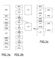
- FIG. 2 ( a ) shows an example of a program, and its most parallel execution.
- the initial program is written down in a sequential procedural language, such as C. It consists of high-priority tasks HPi, low-priority tasks LPi, and tasks CPi that can run on an independent co-processor.
- a compile-time dependency analysis determines the partial order of the tasks, as shown in the example of FIG. 2 ( b ).
- the low-priority task LP 1 can be started immediately and does not have any dependency from other tasks, while the low-priority task LP 7 is dependent from the execution of the high-priority task HP 4 .
- FIG. 2 ( c ) shows the desired execution flow of this program. If any high-priority task is available for execution on the general or main processor, it should be started immediately. If there is no more high-priority task available for execution, the main processor can spend its time for executing low-priority tasks.
- Such a scheduling is known as pre-emptive scheduling and is described for example in J. L. Peterson et al., ‘Operating System Concepts’, Addison Wesley, 1986.
- the dependency analysis can be simplified to an analysis where high-priority tasks and co-processor tasks are sequenced in the order of the C program, and where low-priority tasks are parallelized to this sequence as soon as possible.
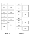
- FIG. 3 shows an example of two different execution traces which result from the same program and its dependency analysis and which are caused by different run-time delays of the co-processor tasks CP 3 and CP 5 .
- FIG. 3 ( a ) shows a first execution trace, where the co-processor tasks CP 3 and CP 5 are executed at short run-time delays, so that high-priority tasks can be performed at earlier stages.
- FIG. 3 ( b ) shows a second execution trace, where the co-processor tasks CP 3 and CP 5 take more cycles, so that the main processor has longer waiting periods for executing the low-priority task LP 1 and the high-priority tasks HP 6 , HP 8 and HP 10 are executed at a later stage.
- task switching is executed by accessing at least two memory stacks in response to synchronization instructions inserted to the program routine.
- Initial push of tasks will take one cycle and meanwhile the synchronizing instructions can be invoked simultaneously with the usual program instructions and allow for task switching with no overhead.
- efficient switching between prioritized tasks can be achieved.
- a runtime handling means may be provided for monitoring the at least two memory stacks and for providing access to the top of a non-empty memory stack with the highest priority. Thereby, it can be assured that high-priority tasks will be prioritized over low-priority tasks when accessing the memory stacks.
- the synchronization instructions may comprise a start instruction for setting a program counter of one of the processor means to a given task address and for popping a current tasks of another one of the processor means from a high-priority one of the at least two memory stacks. This instruction provides an efficient switching between high-priority tasks of processor means.
- the synchronization instructions may comprise a stop instruction for pushing a given task on a high priority one of the at least two memory stacks, and for replacing the top of a low-priority one of the at least two memory stacks with a next task address of one of the processor means.
- This instruction provides for an efficient back-switching after execution of a dependent task at the other processor means.
- the synchronization instructions may comprise a hold instruction for popping a current task from a high-priority one of the at least two memory stacks and for storing a given task address.
- This optional hold instruction can be used advantageously in connection with pre-emptive high-priority tasks.
- the task switching means may be adapted to derive the given task address from the instruction itself. As the given task address is already included in the synchronization instruction, no additional task switching cycles are required for address retrieval.
- the insertion of the synchronization instructions into the assembly code of the program routine may be based on an analyzing step of dependences of tasks of the program routine. Thereby, an automatic modification of the assembly code can be achieved without requiring any external interaction.
- the switching between low- and high-priority tasks can be invoked simultaneously with usual or conventional instructions of the program routine. By this measure, additional processing cycles for task switching can be prevented.
- FIG. 1 shows a schematic block diagram of a processor device according to the preferred embodiment
- FIG. 2 shows a schematic diagram of an example of a parallelized execution flow with task switching
- FIG. 3 shows schematic representations of different execution traces depending on run-time delays
- FIG. 4 shows a double-sided stack memory and alternative separate stack memories for different priority levels, according to the preferred embodiment
- FIG. 5 shows a schematic flow diagram of an execution of synchronization instructions without overhead
- FIG. 6 shows a schematic flow diagram of an execution of synchronization instructions which allow pre-emption of high-priority tasks, according to the preferred embodiment
- FIG. 7 shows a schematic flow diagram showing a first example of execution of synchronization instructions according to the preferred embodiment
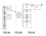
- FIG. 8 shows a schematic flow diagram showing a second example of execution of synchronization instructions according to the preferred embodiment.
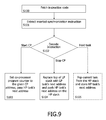
- FIG. 9 shows a schematic flow diagram of the processing of synchronization instructions according to the preferred embodiment.
- processor device having a main processor 20 and a co-processor 30 for performing task switching of two-level priority tasks based on a double-sided stack 60 with support functions.
- FIG. 1 shows a schematic block diagram of the proposed architecture which comprises a main processor 20 and a co-processor 30 for dedicated tasks, which both have own access to a memory system 10 in which program codes or routines and processing data are stored. At least a portion of the memory system 10 , which may consist of a single or a plurality of memory circuits or devices, may be shared by both processors, which means that both processors may access the same shared memory locations.
- the main processor 20 may host an operating system which performs various functions including system memory management, system task management and other native tasks running on the system.
- a task scheduling function or unit 50 is provided for controlling switching of tasks between the main processor 20 and the co-processor 30 .
- prioritized tasks are stored in respective priority-dependent stacks of a stack memory 60 which can be accessed by the task switching unit 50 via a runtime handling function or unit 40 which manages access to the stack memory 60 .
- the task scheduling unit 50 and the runtime handling unit 40 may be implemented as separate software or hardware functions or may be provided as a part of the operating system running on the main processor 20 .
- the software implementation naturally leads to a tradeoff with regard to efficiency.
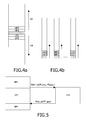
- FIG. 4 ( a ) shows a first example of the stack memory 60 arranged as a double-sided stack, wherein the runtime handling unit 40 provides support for task switching.
- task switching is restricted to two-level priority tasks, which may be used in a corresponding digital signal processing context with high-priority tasks and low-priority tasks.
- the stack memory 60 comprises a low-priority stack 64 and a high-priority stack 62 which may be separated by an empty stack or stack field or by a predetermined bit or information pattern (as indicated by the hatched portion in FIG. 4 ( a )).
- the present invention is not restricted to a double-sided stack or two separate stack memories. It can be extended to use separate stacks for different levels of priority, e.g. high priority, medium priority, low priority or even more levels of priority.
- FIG. 4 ( b ) shows a second example of the stack memory 60 , where separate stack memories each representing a dedicated level of priority are provided.
- the lowest stack field (as indicated by the hatched portion) is empty or contains a predetermined information indicating the end of the stack.
- stack memory may be implemented based on any stack mechanism in any kind of memory device or circuit.
- the task scheduling unit 50 can access both main processor 20 and co-processor 30 . Furthermore, the task scheduling unit 50 can access the memory system 10 .
- the task scheduling unit 50 in connection with the runtime handling unit 40 and the stack memory 60 will support task switching by handling synchronization instructions at runtime. The instructions will be inserted into the assembly code of a program or routine stored in the memory system 10 , based on the results of a dependency analysis which may be performed by the operating system. Initial push of tasks to the stack memory 60 will take one cycle and meanwhile the synchronizing instructions such as the start of a co-processor task, the finishing of a co-processor task and the switching between low- and high-priority tasks are invoked simultaneously with the usual instruction. The incorporation of the additional synchronization instructions may be achieved simply by adding an extra bit to the usual instructions, to thereby allow task switching with no overhead.
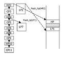
- FIG. 5 shows a schematic flow diagram indicating execution of synchronization instructions without overhead.
- the synchronization instructions are attached to the usual instructions.
- a start instruction ‘Start_cp(CP_address, HP_address)’ is inserted at the end of a high-priority task HP 2 , so as to set the co-processor's program counter to the given address ‘CP_address’, and to pass the high-priority task's next address ‘HP_address’.
- this start instruction leads to a pop operation which pops the high-priority task calling the co-processor 30 from the high-priority stack 62 of the stack memory 60 .
- a stop instruction ‘Stop_cp(HP_address)’ is incorporated, which replaces the top of the low-priority stack 64 with the low-priority task's next address ‘LP_address’ and pushes the high-priority task's next address ‘HP_address’ on the low-priority stack 64 .
- the runtime handling unit 40 observes both high-priority stack 62 and low-priority stack 64 and executes tasks on top of the high-priority stack 62 , and if no task is left there, it will execute tasks on top of the low-priority stack 64 .
- Synchronization instructions are thus inserted or incorporated into the assembly code, to thereby control task switching.
- the stack memory 60 with the runtime handling unit 40 and the task switching unit 50 will support task switching by handling these synchronization instructions at runtime.
- a start instruction and a stop instruction may be used.
- an additional hold instruction may be provided for pre-emptive high-priority tasks, as explained in the following.
- FIG. 6 shows a schematic flow diagram of corresponding synchronization instructions executed without overhead, which allow pre-emption of high-priority tasks at critical dependencies. This solution can be used in cases where a more detailed dependence analysis is performed, allowing a high-priority task to proceed its execution towards the point that actually requires information from the co-processor task.
- a start instruction ‘Start_cp(CP_address)’ is inserted, which sets the co-processor's program counter to a given address ‘CP_address’.
- a hold instruction ‘Hold_task (HP_address)’ is inserted, which pops the current high-priority task from the high-priority stack 62 and stores the high-priority task's next address ‘HP_address’.
- a stop instruction ‘Stop_cp’ is added which saves the low-priority task's next address to the low-priority stack 64 if a high-priority task is on hold, and pushes the high-priority task's next address on the high-priority stack 62 .
- FIG. 7 ( a ) indicates the result of the dependency analysis of the operating system
- FIG. 7 ( b ) indicates contents of the stack memory 60
- FIG. 7 ( c ) indicates the running program of the main processor 20 .
- a high-priority task appears, it will be pushed by the task scheduling unit 50 via the runtime handling unit 40 on top of the high-priority stack 62 , causing the program counter of the main processor 20 to switch to a memory address of the memory system 10 where this high-priority task HP 2 is located.
- the first low-priority task LP 1 will be pushed on the top of the low-priority stack 64 by a corresponding push operation.
- FIG. 8 shows a situation when the first high-priority task HP 2 has been finished and issues a switch instruction. If the high-priority stack 62 contains the next high-priority task HP 4 , the runtime handling unit 40 will control access to the stack memory 60 in such a manner that the high-priority task HP 4 will be executed as long as the task scheduling unit 50 does not determine that it has dependency on the co-processor task CP 3 running simultaneously. If the high-priority stack 62 is empty or the next high-priority task on the high-priority stack 62 has a dependency on the simultaneously running co-processor task CP 3 (which means that the high-priority task HP 4 has to wait until the co-processor 30 is finished, as indicated in FIG.
- the program counter will jump to the first low-priority task LP 1 on the low-priority stack 64 and execute this task until an interrupt from the co-processor 30 has been received.
- This interrupt causes the low-priority task LP 1 to abort and changes the program counter to the next high-priority task HP 4 in the line or queue of the high-priority stack 62 .
- support for procedural languages is maintained as long as function invocations triggered by the synchronization instructions are treated as calls or jumps to high-priority or co-processor tasks.
- the corresponding function is pushed on top of the high-priority stack 62 or invoked as a co-processor task.
- FIG. 9 shows a schematic flow diagram of a control procedure as executed by the task scheduling unit 50 .
- a next instruction code (assembly code) is fetched from the memory system 10 and, if provided, a synchronization instruction is extracted in step S 101 .
- the synchronization instruction is decoded in step S 102 to determine the kind of synchronization instruction for task scheduling.
- the decoding step S 102 may determine a start instruction for the co-processor 30 , so that the procedure branches to a step S 103 in which the program counter PC 2 of the co-processor 30 is set to the given co-processor address, and the high-priority task's next address is passed.
- step S 104 the procedure branches to step S 104 , where the task scheduling unit 50 acts to replace the top of the low-priority stack 64 with the low-priority task's next address and to push the high-priority tasks next address on the high-priority stack 62 .
- a hold instruction may be decoded in step S 102 and the procedure may then branch to step S 105 , so that the task scheduling unit 50 acts to pop the current task from the high-priority stack 62 and to store the high-priority tasks next address.
- a task scheduling scheme is suggested, where tasks of a program routine are selectively stored in at least two memory stack mechanisms of different priorities based on the allocated priorities. Switching of tasks executed at least two processor means is controlled by accessing the at least two memory stack mechanisms in response to synchronization instructions inserted to the program routine. Thereby, efficient zero-cycle task switching between prioritized tasks can be achieved.
- the proposed solution according to the above preferred embodiment can be introduced in any main/co-processor scenario with reservation for eventual extra cycles for context switches or state savings in case of shared registers.
- the invention is applicable in any domain where tasks can fill empty processing slots when no high-priority tasks are executed. Examples for such domains are image vision, game applications with user interaction and background scenes, security applications with dangerous and non-dangerous situations, collision detection applications with dangerous and non-dangerous situations, GPS (Global Positioning System) applications with wrong direction processing and route following processing, real-time signal processing with streaming processing and user interface processing, mobile phone applications with phone call processing and game processing, etc.
- the structure of the stack memory 60 is not restricted to the above double-sided memory stack, and any kind of stack memory or stack memory mechanism in other types of memories can be used.
- the present invention can be used for switching tasks between more than two processor devices.
- other synchronization instructions with other notations can be used for controlling task switching in connection with the stack memory 60 .
- They may be incorporated or added to the conventional or usual program instructions in any way or length. The preferred embodiments may thus vary within the scope of the attached claims.
Landscapes
- Engineering & Computer Science (AREA)
- Theoretical Computer Science (AREA)
- Software Systems (AREA)
- General Engineering & Computer Science (AREA)
- Physics & Mathematics (AREA)
- General Physics & Mathematics (AREA)
- Executing Machine-Instructions (AREA)
- Multi Processors (AREA)
- Vehicle Body Suspensions (AREA)
- Steering Control In Accordance With Driving Conditions (AREA)
- Power Steering Mechanism (AREA)
- Devices For Executing Special Programs (AREA)
Applications Claiming Priority (3)
| Application Number | Priority Date | Filing Date | Title |
|---|---|---|---|
| EP04106190 | 2004-11-30 | ||
| EP04106190.4 | 2004-11-30 | ||
| PCT/IB2005/053897 WO2006072841A2 (fr) | 2004-11-30 | 2005-11-24 | Basculement efficace entre des taches classees par ordre de priorite |
Publications (1)
| Publication Number | Publication Date |
|---|---|
| US20080098398A1 true US20080098398A1 (en) | 2008-04-24 |
Family
ID=36228556
Family Applications (1)
| Application Number | Title | Priority Date | Filing Date |
|---|---|---|---|
| US11/719,964 Abandoned US20080098398A1 (en) | 2004-11-30 | 2005-11-24 | Efficient Switching Between Prioritized Tasks |
Country Status (7)
| Country | Link |
|---|---|
| US (1) | US20080098398A1 (fr) |
| EP (1) | EP1820100B1 (fr) |
| JP (1) | JP2008522277A (fr) |
| CN (1) | CN100535862C (fr) |
| AT (1) | ATE406613T1 (fr) |
| DE (1) | DE602005009398D1 (fr) |
| WO (1) | WO2006072841A2 (fr) |
Cited By (6)
| Publication number | Priority date | Publication date | Assignee | Title |
|---|---|---|---|---|
| US20070016908A1 (en) * | 2005-07-15 | 2007-01-18 | Manabu Kuroda | Parallel operation apparatus |
| US20120192147A1 (en) * | 2011-01-25 | 2012-07-26 | Argen Wong | Develop real time software without an RTOS |
| US8276132B1 (en) * | 2007-11-12 | 2012-09-25 | Nvidia Corporation | System and method for representing and managing a multi-architecture co-processor application program |
| US8281294B1 (en) * | 2007-11-12 | 2012-10-02 | Nvidia Corporation | System and method for representing and managing a multi-architecture co-processor application program |
| US20140173610A1 (en) * | 2006-04-05 | 2014-06-19 | Maxwell Technologies, Inc. | Methods and apparatus for managing and controlling power consumption and heat generation in computer systems |
| US8973009B2 (en) * | 2009-02-24 | 2015-03-03 | Commissariat A L'energie Atomique Et Aux Energies Alternatives | Allocation and control unit for controlling parallel execution of threads on auxiliary processing units |
Families Citing this family (3)
| Publication number | Priority date | Publication date | Assignee | Title |
|---|---|---|---|---|
| JP5155336B2 (ja) * | 2008-01-15 | 2013-03-06 | カーネロンシリコン株式会社 | タスク処理装置 |
| CN101290590B (zh) * | 2008-06-03 | 2012-01-11 | 北京中星微电子有限公司 | 一种嵌入式操作系统中切换任务的方法和单元 |
| CN101290591B (zh) * | 2008-06-03 | 2011-10-12 | 北京中星微电子有限公司 | 一种嵌入式操作系统中切换任务的方法和单元 |
Citations (21)
| Publication number | Priority date | Publication date | Assignee | Title |
|---|---|---|---|---|
| US4286322A (en) * | 1979-07-03 | 1981-08-25 | International Business Machines Corporation | Task handling apparatus |
| US4435780A (en) * | 1981-06-16 | 1984-03-06 | International Business Machines Corporation | Separate stack areas for plural processes |
| US4868782A (en) * | 1986-06-11 | 1989-09-19 | International Business Machines Corporation | Display terminal |
| US5161226A (en) * | 1991-05-10 | 1992-11-03 | Jmi Software Consultants Inc. | Microprocessor inverse processor state usage |
| US5379427A (en) * | 1989-04-13 | 1995-01-03 | Mitsubishi Denki Kabushiki Kaisha | Task tracing apparatus in a multitask operating system |
| US6157989A (en) * | 1998-06-03 | 2000-12-05 | Motorola, Inc. | Dynamic bus arbitration priority and task switching based on shared memory fullness in a multi-processor system |
| US6243793B1 (en) * | 1995-07-27 | 2001-06-05 | Intel Corporation | Protocol for arbitrating access to a shared memory area using historical state information |
| US20020057708A1 (en) * | 2000-07-31 | 2002-05-16 | Galbi Duane E. | Enhancing performance by pre-fetching and caching data directly in a communication processor's register set |
| US20020099933A1 (en) * | 2000-11-27 | 2002-07-25 | Nevill Edward Colles | Data processing apparatus and method for saving return state |
| US20030014474A1 (en) * | 2001-05-30 | 2003-01-16 | Mckaig Ray S. | Alternate zero overhead task change circuit |
| US20030051124A1 (en) * | 1997-08-01 | 2003-03-13 | Dowling Eric M. | Virtual shadow registers and virtual register windows |
| US20040025161A1 (en) * | 2002-07-31 | 2004-02-05 | Texas Instruments Incorporated | Concurrent task execution in a multi-processor, single operating system environment |
| US6732169B1 (en) * | 1999-09-27 | 2004-05-04 | Alcatel | Network transmission circuit control method and system |
| US20040103410A1 (en) * | 2000-03-30 | 2004-05-27 | Junji Sakai | Program conversion apparatus and method as well as recording medium |
| US6751711B1 (en) * | 2000-10-27 | 2004-06-15 | Nortel Networks Limited | Methods and systems for process rollback in a shared memory parallel processor computing environment |
| US20040163083A1 (en) * | 2003-02-19 | 2004-08-19 | Hong Wang | Programmable event driven yield mechanism which may activate other threads |
| US20050015768A1 (en) * | 2002-12-31 | 2005-01-20 | Moore Mark Justin | System and method for providing hardware-assisted task scheduling |
| US20050108720A1 (en) * | 2003-11-14 | 2005-05-19 | Stmicroelectronics, Inc. | System and method for efficiently executing single program multiple data (SPMD) programs |
| US20050149931A1 (en) * | 2003-11-14 | 2005-07-07 | Infineon Technologies Ag | Multithread processor architecture for triggered thread switching without any cycle time loss, and without any switching program command |
| US6993018B1 (en) * | 1999-08-03 | 2006-01-31 | Telefonaktiebolaget Lm Ericsson (Publ) | Priority signaling for cell switching |
| US20060090019A1 (en) * | 2003-02-11 | 2006-04-27 | Lewis Jody W | Asynchronous communications technique |
Family Cites Families (3)
| Publication number | Priority date | Publication date | Assignee | Title |
|---|---|---|---|---|
| EP0706126A1 (fr) * | 1994-10-07 | 1996-04-10 | International Business Machines Corporation | Planification de tâches à niveaux multiples de priorité |
| US6243735B1 (en) * | 1997-09-01 | 2001-06-05 | Matsushita Electric Industrial Co., Ltd. | Microcontroller, data processing system and task switching control method |
| JP4072271B2 (ja) * | 1999-02-19 | 2008-04-09 | 株式会社日立製作所 | 複数のオペレーティングシステムを実行する計算機 |
-
2005
- 2005-11-24 CN CNB2005800408842A patent/CN100535862C/zh not_active Expired - Fee Related
- 2005-11-24 EP EP05826687A patent/EP1820100B1/fr not_active Expired - Lifetime
- 2005-11-24 US US11/719,964 patent/US20080098398A1/en not_active Abandoned
- 2005-11-24 WO PCT/IB2005/053897 patent/WO2006072841A2/fr not_active Ceased
- 2005-11-24 DE DE602005009398T patent/DE602005009398D1/de not_active Expired - Lifetime
- 2005-11-24 JP JP2007542478A patent/JP2008522277A/ja not_active Revoked
- 2005-11-24 AT AT05826687T patent/ATE406613T1/de not_active IP Right Cessation
Patent Citations (21)
| Publication number | Priority date | Publication date | Assignee | Title |
|---|---|---|---|---|
| US4286322A (en) * | 1979-07-03 | 1981-08-25 | International Business Machines Corporation | Task handling apparatus |
| US4435780A (en) * | 1981-06-16 | 1984-03-06 | International Business Machines Corporation | Separate stack areas for plural processes |
| US4868782A (en) * | 1986-06-11 | 1989-09-19 | International Business Machines Corporation | Display terminal |
| US5379427A (en) * | 1989-04-13 | 1995-01-03 | Mitsubishi Denki Kabushiki Kaisha | Task tracing apparatus in a multitask operating system |
| US5161226A (en) * | 1991-05-10 | 1992-11-03 | Jmi Software Consultants Inc. | Microprocessor inverse processor state usage |
| US6243793B1 (en) * | 1995-07-27 | 2001-06-05 | Intel Corporation | Protocol for arbitrating access to a shared memory area using historical state information |
| US20030051124A1 (en) * | 1997-08-01 | 2003-03-13 | Dowling Eric M. | Virtual shadow registers and virtual register windows |
| US6157989A (en) * | 1998-06-03 | 2000-12-05 | Motorola, Inc. | Dynamic bus arbitration priority and task switching based on shared memory fullness in a multi-processor system |
| US6993018B1 (en) * | 1999-08-03 | 2006-01-31 | Telefonaktiebolaget Lm Ericsson (Publ) | Priority signaling for cell switching |
| US6732169B1 (en) * | 1999-09-27 | 2004-05-04 | Alcatel | Network transmission circuit control method and system |
| US20040103410A1 (en) * | 2000-03-30 | 2004-05-27 | Junji Sakai | Program conversion apparatus and method as well as recording medium |
| US20020057708A1 (en) * | 2000-07-31 | 2002-05-16 | Galbi Duane E. | Enhancing performance by pre-fetching and caching data directly in a communication processor's register set |
| US6751711B1 (en) * | 2000-10-27 | 2004-06-15 | Nortel Networks Limited | Methods and systems for process rollback in a shared memory parallel processor computing environment |
| US20020099933A1 (en) * | 2000-11-27 | 2002-07-25 | Nevill Edward Colles | Data processing apparatus and method for saving return state |
| US20030014474A1 (en) * | 2001-05-30 | 2003-01-16 | Mckaig Ray S. | Alternate zero overhead task change circuit |
| US20040025161A1 (en) * | 2002-07-31 | 2004-02-05 | Texas Instruments Incorporated | Concurrent task execution in a multi-processor, single operating system environment |
| US20050015768A1 (en) * | 2002-12-31 | 2005-01-20 | Moore Mark Justin | System and method for providing hardware-assisted task scheduling |
| US20060090019A1 (en) * | 2003-02-11 | 2006-04-27 | Lewis Jody W | Asynchronous communications technique |
| US20040163083A1 (en) * | 2003-02-19 | 2004-08-19 | Hong Wang | Programmable event driven yield mechanism which may activate other threads |
| US20050108720A1 (en) * | 2003-11-14 | 2005-05-19 | Stmicroelectronics, Inc. | System and method for efficiently executing single program multiple data (SPMD) programs |
| US20050149931A1 (en) * | 2003-11-14 | 2005-07-07 | Infineon Technologies Ag | Multithread processor architecture for triggered thread switching without any cycle time loss, and without any switching program command |
Cited By (7)
| Publication number | Priority date | Publication date | Assignee | Title |
|---|---|---|---|---|
| US20070016908A1 (en) * | 2005-07-15 | 2007-01-18 | Manabu Kuroda | Parallel operation apparatus |
| US20140173610A1 (en) * | 2006-04-05 | 2014-06-19 | Maxwell Technologies, Inc. | Methods and apparatus for managing and controlling power consumption and heat generation in computer systems |
| US9459919B2 (en) * | 2006-04-05 | 2016-10-04 | Data Device Corporation | Methods and apparatus for managing and controlling power consumption and heat generation in computer systems |
| US8276132B1 (en) * | 2007-11-12 | 2012-09-25 | Nvidia Corporation | System and method for representing and managing a multi-architecture co-processor application program |
| US8281294B1 (en) * | 2007-11-12 | 2012-10-02 | Nvidia Corporation | System and method for representing and managing a multi-architecture co-processor application program |
| US8973009B2 (en) * | 2009-02-24 | 2015-03-03 | Commissariat A L'energie Atomique Et Aux Energies Alternatives | Allocation and control unit for controlling parallel execution of threads on auxiliary processing units |
| US20120192147A1 (en) * | 2011-01-25 | 2012-07-26 | Argen Wong | Develop real time software without an RTOS |
Also Published As
| Publication number | Publication date |
|---|---|
| EP1820100B1 (fr) | 2008-08-27 |
| CN100535862C (zh) | 2009-09-02 |
| EP1820100A2 (fr) | 2007-08-22 |
| CN101065728A (zh) | 2007-10-31 |
| ATE406613T1 (de) | 2008-09-15 |
| JP2008522277A (ja) | 2008-06-26 |
| WO2006072841A2 (fr) | 2006-07-13 |
| WO2006072841A3 (fr) | 2006-10-12 |
| DE602005009398D1 (de) | 2008-10-09 |
Similar Documents
| Publication | Publication Date | Title |
|---|---|---|
| US9104425B2 (en) | Apparatus and method for handling exception events | |
| US7950016B2 (en) | Apparatus for switching the task to be completed in a processor by switching to the task assigned time slot | |
| US7734881B2 (en) | Adapting RCU for real-time operating system usage | |
| US6857060B2 (en) | System, apparatus and method for prioritizing instructions and eliminating useless instructions | |
| KR101255382B1 (ko) | 운영체제에 친숙한 부트로더 | |
| US20090271790A1 (en) | Computer architecture | |
| JP2003288237A (ja) | 制御装置における実行時間測定装置及び実行時間測定方法 | |
| EP2565786A1 (fr) | Dispositif de traitement d'informations et procédé de commutation de tâches | |
| JP2011086298A (ja) | プログラム・フロー制御 | |
| EP1820100B1 (fr) | Basculement efficace entre des taches classees par ordre de priorite | |
| CN113918336B (zh) | 基于多核CPU的FreeRTOS运行任务方法及装置 | |
| CN111538535B (zh) | 一种cpu指令处理方法、控制器和中央处理单元 | |
| US7765533B2 (en) | Automatic task distribution in scalable processors | |
| US8490098B2 (en) | Concomitance scheduling commensal threads in a multi-threading computer system | |
| KR100817947B1 (ko) | 인터럽트 서비스 방법 및 프로세서 | |
| US20050132171A1 (en) | Method for register allocation during instruction scheduling | |
| US7603673B2 (en) | Method and system for reducing context switch times | |
| US7412597B2 (en) | Computer system and booting method thereof | |
| US9619277B2 (en) | Computer with plurality of processors sharing process queue, and process dispatch processing method | |
| JP2008537248A (ja) | デジタルシグナルプロセッサ上でのマルチタスクの実施 | |
| KR20010012752A (ko) | Risc 프로세서 | |
| HK1104102B (en) | Method and system for concurrent execution of mutiple kernels | |
| HK1104102A1 (zh) | 用於多個內核的並行執行的方法和系統 |
Legal Events
| Date | Code | Title | Description |
|---|---|---|---|
| AS | Assignment |
Owner name: KONINKLIJKE PHILIPS ELECTRONICS N V, NETHERLANDS Free format text: ASSIGNMENT OF ASSIGNORS INTEREST;ASSIGNORS:HEIJLIGERS, MARCUS JOSEPHUS MARIA;JUHAS, ELEONORA;REEL/FRAME:019330/0366;SIGNING DATES FROM 20060815 TO 20060818 |
|
| STCB | Information on status: application discontinuation |
Free format text: ABANDONED -- FAILURE TO PAY ISSUE FEE |
|
| STCB | Information on status: application discontinuation |
Free format text: ABANDONED -- FAILURE TO PAY ISSUE FEE |