US20030196842A1 - Driving apparatus for vehicle - Google Patents
Driving apparatus for vehicle Download PDFInfo
- Publication number
- US20030196842A1 US20030196842A1 US10/414,045 US41404503A US2003196842A1 US 20030196842 A1 US20030196842 A1 US 20030196842A1 US 41404503 A US41404503 A US 41404503A US 2003196842 A1 US2003196842 A1 US 2003196842A1
- Authority
- US
- United States
- Prior art keywords
- shaft
- rotor
- driving apparatus
- gear
- hollow shaft
- Prior art date
- Legal status (The legal status is an assumption and is not a legal conclusion. Google has not performed a legal analysis and makes no representation as to the accuracy of the status listed.)
- Granted
Links
Images


Classifications
-
- B—PERFORMING OPERATIONS; TRANSPORTING
- B60—VEHICLES IN GENERAL
- B60K—ARRANGEMENT OR MOUNTING OF PROPULSION UNITS OR OF TRANSMISSIONS IN VEHICLES; ARRANGEMENT OR MOUNTING OF PLURAL DIVERSE PRIME-MOVERS IN VEHICLES; AUXILIARY DRIVES FOR VEHICLES; INSTRUMENTATION OR DASHBOARDS FOR VEHICLES; ARRANGEMENTS IN CONNECTION WITH COOLING, AIR INTAKE, GAS EXHAUST OR FUEL SUPPLY OF PROPULSION UNITS IN VEHICLES
- B60K6/00—Arrangement or mounting of plural diverse prime-movers for mutual or common propulsion, e.g. hybrid propulsion systems comprising electric motors and internal combustion engines ; Control systems therefor, i.e. systems controlling two or more prime movers, or controlling one of these prime movers and any of the transmission, drive or drive units Informative references: mechanical gearings with secondary electric drive F16H3/72; arrangements for handling mechanical energy structurally associated with the dynamo-electric machine H02K7/00; machines comprising structurally interrelated motor and generator parts H02K51/00; dynamo-electric machines not otherwise provided for in H02K see H02K99/00
- B60K6/20—Arrangement or mounting of plural diverse prime-movers for mutual or common propulsion, e.g. hybrid propulsion systems comprising electric motors and internal combustion engines ; Control systems therefor, i.e. systems controlling two or more prime movers, or controlling one of these prime movers and any of the transmission, drive or drive units Informative references: mechanical gearings with secondary electric drive F16H3/72; arrangements for handling mechanical energy structurally associated with the dynamo-electric machine H02K7/00; machines comprising structurally interrelated motor and generator parts H02K51/00; dynamo-electric machines not otherwise provided for in H02K see H02K99/00 the prime-movers consisting of electric motors and internal combustion engines, e.g. HEVs
- B60K6/22—Arrangement or mounting of plural diverse prime-movers for mutual or common propulsion, e.g. hybrid propulsion systems comprising electric motors and internal combustion engines ; Control systems therefor, i.e. systems controlling two or more prime movers, or controlling one of these prime movers and any of the transmission, drive or drive units Informative references: mechanical gearings with secondary electric drive F16H3/72; arrangements for handling mechanical energy structurally associated with the dynamo-electric machine H02K7/00; machines comprising structurally interrelated motor and generator parts H02K51/00; dynamo-electric machines not otherwise provided for in H02K see H02K99/00 the prime-movers consisting of electric motors and internal combustion engines, e.g. HEVs characterised by apparatus, components or means specially adapted for HEVs
- B60K6/36—Arrangement or mounting of plural diverse prime-movers for mutual or common propulsion, e.g. hybrid propulsion systems comprising electric motors and internal combustion engines ; Control systems therefor, i.e. systems controlling two or more prime movers, or controlling one of these prime movers and any of the transmission, drive or drive units Informative references: mechanical gearings with secondary electric drive F16H3/72; arrangements for handling mechanical energy structurally associated with the dynamo-electric machine H02K7/00; machines comprising structurally interrelated motor and generator parts H02K51/00; dynamo-electric machines not otherwise provided for in H02K see H02K99/00 the prime-movers consisting of electric motors and internal combustion engines, e.g. HEVs characterised by apparatus, components or means specially adapted for HEVs characterised by the transmission gearings
-
- B—PERFORMING OPERATIONS; TRANSPORTING
- B60—VEHICLES IN GENERAL
- B60K—ARRANGEMENT OR MOUNTING OF PROPULSION UNITS OR OF TRANSMISSIONS IN VEHICLES; ARRANGEMENT OR MOUNTING OF PLURAL DIVERSE PRIME-MOVERS IN VEHICLES; AUXILIARY DRIVES FOR VEHICLES; INSTRUMENTATION OR DASHBOARDS FOR VEHICLES; ARRANGEMENTS IN CONNECTION WITH COOLING, AIR INTAKE, GAS EXHAUST OR FUEL SUPPLY OF PROPULSION UNITS IN VEHICLES
- B60K1/00—Arrangement or mounting of electrical propulsion units
-
- B—PERFORMING OPERATIONS; TRANSPORTING
- B60—VEHICLES IN GENERAL
- B60K—ARRANGEMENT OR MOUNTING OF PROPULSION UNITS OR OF TRANSMISSIONS IN VEHICLES; ARRANGEMENT OR MOUNTING OF PLURAL DIVERSE PRIME-MOVERS IN VEHICLES; AUXILIARY DRIVES FOR VEHICLES; INSTRUMENTATION OR DASHBOARDS FOR VEHICLES; ARRANGEMENTS IN CONNECTION WITH COOLING, AIR INTAKE, GAS EXHAUST OR FUEL SUPPLY OF PROPULSION UNITS IN VEHICLES
- B60K17/00—Arrangement or mounting of transmissions in vehicles
- B60K17/04—Arrangement or mounting of transmissions in vehicles characterised by arrangement, location, or kind of gearing
- B60K17/16—Arrangement or mounting of transmissions in vehicles characterised by arrangement, location, or kind of gearing of differential gearing
-
- B—PERFORMING OPERATIONS; TRANSPORTING
- B60—VEHICLES IN GENERAL
- B60K—ARRANGEMENT OR MOUNTING OF PROPULSION UNITS OR OF TRANSMISSIONS IN VEHICLES; ARRANGEMENT OR MOUNTING OF PLURAL DIVERSE PRIME-MOVERS IN VEHICLES; AUXILIARY DRIVES FOR VEHICLES; INSTRUMENTATION OR DASHBOARDS FOR VEHICLES; ARRANGEMENTS IN CONNECTION WITH COOLING, AIR INTAKE, GAS EXHAUST OR FUEL SUPPLY OF PROPULSION UNITS IN VEHICLES
- B60K6/00—Arrangement or mounting of plural diverse prime-movers for mutual or common propulsion, e.g. hybrid propulsion systems comprising electric motors and internal combustion engines ; Control systems therefor, i.e. systems controlling two or more prime movers, or controlling one of these prime movers and any of the transmission, drive or drive units Informative references: mechanical gearings with secondary electric drive F16H3/72; arrangements for handling mechanical energy structurally associated with the dynamo-electric machine H02K7/00; machines comprising structurally interrelated motor and generator parts H02K51/00; dynamo-electric machines not otherwise provided for in H02K see H02K99/00
- B60K6/20—Arrangement or mounting of plural diverse prime-movers for mutual or common propulsion, e.g. hybrid propulsion systems comprising electric motors and internal combustion engines ; Control systems therefor, i.e. systems controlling two or more prime movers, or controlling one of these prime movers and any of the transmission, drive or drive units Informative references: mechanical gearings with secondary electric drive F16H3/72; arrangements for handling mechanical energy structurally associated with the dynamo-electric machine H02K7/00; machines comprising structurally interrelated motor and generator parts H02K51/00; dynamo-electric machines not otherwise provided for in H02K see H02K99/00 the prime-movers consisting of electric motors and internal combustion engines, e.g. HEVs
- B60K6/22—Arrangement or mounting of plural diverse prime-movers for mutual or common propulsion, e.g. hybrid propulsion systems comprising electric motors and internal combustion engines ; Control systems therefor, i.e. systems controlling two or more prime movers, or controlling one of these prime movers and any of the transmission, drive or drive units Informative references: mechanical gearings with secondary electric drive F16H3/72; arrangements for handling mechanical energy structurally associated with the dynamo-electric machine H02K7/00; machines comprising structurally interrelated motor and generator parts H02K51/00; dynamo-electric machines not otherwise provided for in H02K see H02K99/00 the prime-movers consisting of electric motors and internal combustion engines, e.g. HEVs characterised by apparatus, components or means specially adapted for HEVs
- B60K6/40—Arrangement or mounting of plural diverse prime-movers for mutual or common propulsion, e.g. hybrid propulsion systems comprising electric motors and internal combustion engines ; Control systems therefor, i.e. systems controlling two or more prime movers, or controlling one of these prime movers and any of the transmission, drive or drive units Informative references: mechanical gearings with secondary electric drive F16H3/72; arrangements for handling mechanical energy structurally associated with the dynamo-electric machine H02K7/00; machines comprising structurally interrelated motor and generator parts H02K51/00; dynamo-electric machines not otherwise provided for in H02K see H02K99/00 the prime-movers consisting of electric motors and internal combustion engines, e.g. HEVs characterised by apparatus, components or means specially adapted for HEVs characterised by the assembly or relative disposition of components
- B60K6/405—Housings
-
- B—PERFORMING OPERATIONS; TRANSPORTING
- B60—VEHICLES IN GENERAL
- B60K—ARRANGEMENT OR MOUNTING OF PROPULSION UNITS OR OF TRANSMISSIONS IN VEHICLES; ARRANGEMENT OR MOUNTING OF PLURAL DIVERSE PRIME-MOVERS IN VEHICLES; AUXILIARY DRIVES FOR VEHICLES; INSTRUMENTATION OR DASHBOARDS FOR VEHICLES; ARRANGEMENTS IN CONNECTION WITH COOLING, AIR INTAKE, GAS EXHAUST OR FUEL SUPPLY OF PROPULSION UNITS IN VEHICLES
- B60K6/00—Arrangement or mounting of plural diverse prime-movers for mutual or common propulsion, e.g. hybrid propulsion systems comprising electric motors and internal combustion engines ; Control systems therefor, i.e. systems controlling two or more prime movers, or controlling one of these prime movers and any of the transmission, drive or drive units Informative references: mechanical gearings with secondary electric drive F16H3/72; arrangements for handling mechanical energy structurally associated with the dynamo-electric machine H02K7/00; machines comprising structurally interrelated motor and generator parts H02K51/00; dynamo-electric machines not otherwise provided for in H02K see H02K99/00
- B60K6/20—Arrangement or mounting of plural diverse prime-movers for mutual or common propulsion, e.g. hybrid propulsion systems comprising electric motors and internal combustion engines ; Control systems therefor, i.e. systems controlling two or more prime movers, or controlling one of these prime movers and any of the transmission, drive or drive units Informative references: mechanical gearings with secondary electric drive F16H3/72; arrangements for handling mechanical energy structurally associated with the dynamo-electric machine H02K7/00; machines comprising structurally interrelated motor and generator parts H02K51/00; dynamo-electric machines not otherwise provided for in H02K see H02K99/00 the prime-movers consisting of electric motors and internal combustion engines, e.g. HEVs
- B60K6/42—Arrangement or mounting of plural diverse prime-movers for mutual or common propulsion, e.g. hybrid propulsion systems comprising electric motors and internal combustion engines ; Control systems therefor, i.e. systems controlling two or more prime movers, or controlling one of these prime movers and any of the transmission, drive or drive units Informative references: mechanical gearings with secondary electric drive F16H3/72; arrangements for handling mechanical energy structurally associated with the dynamo-electric machine H02K7/00; machines comprising structurally interrelated motor and generator parts H02K51/00; dynamo-electric machines not otherwise provided for in H02K see H02K99/00 the prime-movers consisting of electric motors and internal combustion engines, e.g. HEVs characterised by the architecture of the hybrid electric vehicle
- B60K6/48—Parallel type
-
- B—PERFORMING OPERATIONS; TRANSPORTING
- B60—VEHICLES IN GENERAL
- B60K—ARRANGEMENT OR MOUNTING OF PROPULSION UNITS OR OF TRANSMISSIONS IN VEHICLES; ARRANGEMENT OR MOUNTING OF PLURAL DIVERSE PRIME-MOVERS IN VEHICLES; AUXILIARY DRIVES FOR VEHICLES; INSTRUMENTATION OR DASHBOARDS FOR VEHICLES; ARRANGEMENTS IN CONNECTION WITH COOLING, AIR INTAKE, GAS EXHAUST OR FUEL SUPPLY OF PROPULSION UNITS IN VEHICLES
- B60K6/00—Arrangement or mounting of plural diverse prime-movers for mutual or common propulsion, e.g. hybrid propulsion systems comprising electric motors and internal combustion engines ; Control systems therefor, i.e. systems controlling two or more prime movers, or controlling one of these prime movers and any of the transmission, drive or drive units Informative references: mechanical gearings with secondary electric drive F16H3/72; arrangements for handling mechanical energy structurally associated with the dynamo-electric machine H02K7/00; machines comprising structurally interrelated motor and generator parts H02K51/00; dynamo-electric machines not otherwise provided for in H02K see H02K99/00
- B60K6/20—Arrangement or mounting of plural diverse prime-movers for mutual or common propulsion, e.g. hybrid propulsion systems comprising electric motors and internal combustion engines ; Control systems therefor, i.e. systems controlling two or more prime movers, or controlling one of these prime movers and any of the transmission, drive or drive units Informative references: mechanical gearings with secondary electric drive F16H3/72; arrangements for handling mechanical energy structurally associated with the dynamo-electric machine H02K7/00; machines comprising structurally interrelated motor and generator parts H02K51/00; dynamo-electric machines not otherwise provided for in H02K see H02K99/00 the prime-movers consisting of electric motors and internal combustion engines, e.g. HEVs
- B60K6/50—Architecture of the driveline characterised by arrangement or kind of transmission units
- B60K6/52—Driving a plurality of drive axles, e.g. four-wheel drive
-
- B—PERFORMING OPERATIONS; TRANSPORTING
- B60—VEHICLES IN GENERAL
- B60K—ARRANGEMENT OR MOUNTING OF PROPULSION UNITS OR OF TRANSMISSIONS IN VEHICLES; ARRANGEMENT OR MOUNTING OF PLURAL DIVERSE PRIME-MOVERS IN VEHICLES; AUXILIARY DRIVES FOR VEHICLES; INSTRUMENTATION OR DASHBOARDS FOR VEHICLES; ARRANGEMENTS IN CONNECTION WITH COOLING, AIR INTAKE, GAS EXHAUST OR FUEL SUPPLY OF PROPULSION UNITS IN VEHICLES
- B60K1/00—Arrangement or mounting of electrical propulsion units
- B60K2001/001—Arrangement or mounting of electrical propulsion units one motor mounted on a propulsion axle for rotating right and left wheels of this axle
-
- Y—GENERAL TAGGING OF NEW TECHNOLOGICAL DEVELOPMENTS; GENERAL TAGGING OF CROSS-SECTIONAL TECHNOLOGIES SPANNING OVER SEVERAL SECTIONS OF THE IPC; TECHNICAL SUBJECTS COVERED BY FORMER USPC CROSS-REFERENCE ART COLLECTIONS [XRACs] AND DIGESTS
- Y02—TECHNOLOGIES OR APPLICATIONS FOR MITIGATION OR ADAPTATION AGAINST CLIMATE CHANGE
- Y02T—CLIMATE CHANGE MITIGATION TECHNOLOGIES RELATED TO TRANSPORTATION
- Y02T10/00—Road transport of goods or passengers
- Y02T10/60—Other road transportation technologies with climate change mitigation effect
- Y02T10/62—Hybrid vehicles
Definitions
- the present invention relates to a driving apparatus for vehicle, having an electric motor as a prime driving source (mover) for driving drive wheels.
- An electric vehicle employs the electric motor, namely, a motor as a prime mover
- a hybrid vehicle is one employing the electric motor and an internal combustion engine as a prime mover.
- a driving apparatus which is provided with: an electric motor; a speed reduction mechanism for reducing speeds of its rotor shaft; and a differential gear unit, namely, a differential mechanism, for absorbing the difference in rotation between left and right drive wheels in turning the vehicle.
- the electric motor, the speed reduction mechanism and the differential gear unit are incorporated in a case, so that power of the electric motor is transmitted to the drive wheels through a drive shaft coupling the differential gear unit and the left and right drive wheels.
- the driving apparatus comprises: a rotor shaft concentric with a rotor of an electric motor; a reduction shaft provided with a first speed reduction gear train between this rotor shaft and another rotor shaft disposed in parallel thereto; and a differential gear unit provided with a final reduction driven gear, which is engaged with a final reduction drive gear fixed to the reduction shaft.
- the driving apparatus is therefore formed into a parallel three-shaft structure in which an axle shaft, the rotor shaft, and the reduction shaft are parallel to one another, the axle shaft being fixed to a bevel gear of the differential gear unit and coupled to a drive shaft.
- the driving apparatus for a vehicle having the electric motor, three shafts parallel to one another are incorporated in its housing, whereby a size of the width direction of the driving apparatus, that is, a size of the radial direction of each shaft, is increased and the in-vehicle performance of the driving apparatus is deteriorated.
- the driving apparatus needs to incorporate at least eight ball bearings including a ball bearing for supporting the rotor, whereby there has been a problem such that the structure of the driving apparatus becomes complicated.
- An object of the present invention is to provide a driving apparatus for vehicle, which is small in size and excellent in-vehicle performance.
- Another object of the present invention is to provide a driving apparatus having a two-shaft structure.
- a driving apparatus for vehicle comprises: a differential gear unit having a differential case provided with a final reduction driven gear, and two axle shafts respectively coupled to drive wheels; the electric motor having a rotor fixed to a hollow rotor shaft that is coaxially disposed outside one of said axle shafts; and a reduction shaft disposed in parallel to said axle shafts, and provided with a driven gear that is engaged with a drive gear fixed to said rotor shaft and with a final reduction drive gear that is engaged with said final reduction driven gear.
- the driving apparatus rotatably supports each of said differential case, said rotor shaft and said reduction shaft through two bearings in a unit case.
- said rotor shaft has: an inner hollow shaft provided with said drive gear; and an outer hollow shaft on which said rotor is mounted and that is formed integrally with said inner hollow shaft through a flange protruding outward and radially from the inner hollow shaft.
- the two bearings, supporting said rotor shaft support said inner hollow shaft.
- one of the two bearings supporting said rotor shaft, supports said inner hollow shaft, and the other supports said outer hollow shaft.
- the driving apparatus spline-couples said drive gear onto said inner hollow shaft.
- the driving apparatus forms said drive gear integrally with said inner hollow shaft.
- the driving apparatus for vehicle has a two-shaft structure comprising the axle shaft with which the rotor of the electric motor is concentrically disposed and a reduction shaft disposed in parallel thereto, whereby the size of width of the driving apparatus is reduced and the miniaturization of the driving apparatus is achieved and the in-vehicle performance of the driving apparatus is improved.
- Use of the two-shaft structure also results in a reduction in the number of bearings, thereby allowing for manufacturing the driving apparatus at low costs.
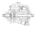
- FIG. 1 is a cross-sectional view showing a driving apparatus for vehicle according to one embodiment of the present invention.
- FIG. 2A is a schematic view of the driving apparatus shown in FIG. 1.
- FIG. 2B is a cross-sectional view taken along the A-A line in FIG. 2A.
- FIG. 3 is a cross-sectional view showing a driving apparatus for vehicle according to another embodiment of the present invention.
- FIG. 4 is a schematic view showing a driving apparatus for vehicle, which has a three-shaft structure, as a comparative example.
- a driving apparatus is mounted in an electric vehicle driving drive wheels only by electric power from a battery, or in a hybrid vehicle driving drive wheels by an internal combustion engine and an electric motor.
- a driving apparatus for front and rear wheels are respectively mounted on its vehicle.
- the driving apparatus is mounted on its vehicle to drive the rear wheels.
- this driving apparatus has a unit case 11 comprising: a motor case 11 a ; a gear case 11 b fixed to one side thereof; and a cover 11 c fixed to the other side thereof, and this unit case 11 is mounted in the vehicle.
- a differential gear unit 12 is rotatably incorporated in the gear case 11 b and has a differential case 14 provided with a reduction driven gear 13 .
- the differential case 14 can be rotated by a ball bearing 15 incorporated in the gear case 11 b and a ball bearing 16 incorporated in the motor case 11 a.
- a bevel gear that is, a side gear 18 a fixed to an axle shaft 17 a coupled to one of the left and right drive wheels through a not-shown drive shaft; and a side gear 18 b fixed to an axle shaft 17 b coupled to the other of the drive wheels through a not-shown drive shaft.
- These side gears 18 a and 18 b are located opposite to each other.
- a pinion shaft 19 is fixed in a direction perpendicular to each rotational center axis of the axle shafts 17 a and 17 b .
- bevel pinions that is, pinion gears 20 a and 20 b facing each other and respectively engaged with the side gears 18 a and 18 b are rotatably mounted.
- a hollow rotor shaft 21 is rotatably incorporated outside one of the axle shafts ( 17 a , 17 b , herein 17 b ) so as to be coaxial therewith, and the rotor shaft 21 has an inner hollow shaft 21 a , and an outer hollow shaft 21 b that is integrally formed with it through a radial direction section 22 (flange) and has a larger diameter than the inner hollow shaft 21 a .
- Ball bearings 23 and 24 are incorporated into the motor case 11 a , and the ball bearing 23 supports the inner hollow shaft 21 a , and the ball bearing 24 supports the outer hollow shaft 21 b.
- an electric motor 25 is disposed outside the rotor shaft 21 .
- the electric motor 25 is a permanent magnet type synchronous motor, which has: a rotor 26 provided with a plurality of permanent magnets corresponding to the number of poles and fixed to the rotor shaft 21 ; and a stator 27 whose a coil portion is incorporated in a slot of a core surrounding the outer circumference of the rotor 26 .
- the stator 27 is fixed to the motor case 11 a with bolts 28 .
- a resolver 29 is fixed to the motor case 11 a .
- the rotor 26 is thus fixed to the outer hollow shaft 21 b of the rotor shaft 21 formed by the inner and outer hollow shafts, thereby allowing for transmitting high torque from the rotor 26 to the rotor shaft 21 .
- a reduction shaft 31 is rotatably mounted in the unit case 11 , and one end of the reduction shaft 31 is supported through a ball bearing 32 by the motor case 11 a , and the other end is supported through a ball bearing 33 by the gear case 11 b .
- This reduction shaft 31 is provided with a driven gear 35 , which is engaged with a drive gear 34 provided in the inner hollow shaft 21 a of the rotor shaft 21 .
- the diameter of the driven gear 35 is set to be larger than that of the drive gear 34 , and these gears 34 and 35 constitute a first reduction gear train.
- the reduction shaft 31 is further provided with a final reduction drive gear 36 engaged with the final reduction driven gear 13 of the differential gear unit 12 , and these reduction gears 13 and 36 constitute a second reduction gear train.
- the axle shaft 17 b is incorporated in the hollow rotor shaft 21 , so that the rotor shaft 21 is coaxial with the axle shaft 17 b and the reduction shaft 31 is disposed in parallel to the axle shaft 17 b .
- the driving apparatus is formed into the two-shaft structure of the rotor shaft 21 and the reduction shaft 31 , whereby its size of the width direction is reduced and the in-vehicle performance is improved.
- six ball bearings are providing in the driving apparatus, thereby allowing for supporting rotating members and simplifying its structure and reducing the manufacturing cost of the driving apparatus.
- FIG. 3 is a cross-sectional view showing a driving apparatus for vehicle according to another embodiment of the present invention.
- the same reference numerals are denoted by the same members as those shown in FIG. 1.
- the ball bearing 24 has a smaller diameter than one shown in FIG. 1, whereby the rotor shaft 21 becomes smaller in rotational resistance than one of the driving apparatus shown in FIG. 1 and the maximum speed of the rotor shaft 21 can be increased.
- the drive gear 34 shown in FIG. 1 is formed integrally with the inner hollow shaft 21 a of the rotor shaft 21 , moreover, the drive gear 34 shown in FIG.
- This driving apparatus is also formed into the two-shaft structure of the rotor shaft 21 and the reduction shaft 31 , whereby the size of the width direction thereof is reduced and the in-vehicle performance is improved. Additionally, the six ball bearings are provided to the driving apparatus, thereby allowing for supporting the rotating members and simplifying the structure and reducing the manufacturing cost of the driving apparatus.
- FIG. 4 is a schematic view showing a driving apparatus having a three-shaft structure as a comparative example.
- the rotor shaft provided with the drive gear 34 the reduction shaft provided with the driven gear 35 engaged with the drive gear 34 , and the axle shaft of the differential gear unit, which has the reduction driven gear 13 , are disposed in parallel to one another.
- the motor case 11 a for accommodating the electric motor and the gear case 11 b for accommodating the differential gear unit are shifted in a radial direction, so that the size of the width direction of the driving apparatus is increased.
- the driving apparatus of the present invention has the two-shaft structure, the size of the width direction of the driving apparatus becomes shortened and the structure thereof can be simplified.
- the present invention is not limited to the above-described embodiments and can variously be modified and changed without departing from the gist thereof.
- the driving apparatus for vehicle according to the present invention can be applied as one for an electric vehicle or hybrid vehicle and applied to not only the case of driving front wheels but also the case of driving rear wheels.
Landscapes
- Engineering & Computer Science (AREA)
- Chemical & Material Sciences (AREA)
- Combustion & Propulsion (AREA)
- Transportation (AREA)
- Mechanical Engineering (AREA)
- Motor Power Transmission Devices (AREA)
- Arrangement Of Transmissions (AREA)
- Gear Transmission (AREA)
- Arrangement Or Mounting Of Propulsion Units For Vehicles (AREA)
- Hybrid Electric Vehicles (AREA)
- Electric Propulsion And Braking For Vehicles (AREA)
- Retarders (AREA)
Abstract
A driving apparatus has a differential gear unit and an electric motor and drives drive wheels of a vehicle. The differential gear unit includes a differential case provided with a final driven gear, and two axle shafts respectively coupled to the drive wheels. A hollow rotor shaft is coaxially disposed outside one of the axle shafts, and a rotor of the electric motor is fixed to this rotor shaft. A reduction shaft is disposed in parallel to the axle shaft, and this reduction shaft is provided with a driven gear, which is engaged with a drive gear provided on the rotor shaft, and a final drive gear engaged with the final driven gear.
Description
- The present invention relates to a driving apparatus for vehicle, having an electric motor as a prime driving source (mover) for driving drive wheels.
- An electric vehicle employs the electric motor, namely, a motor as a prime mover, and a hybrid vehicle is one employing the electric motor and an internal combustion engine as a prime mover. In such a vehicle equipped with the electric motor as the prime mover, there are employed a driving apparatus, which is provided with: an electric motor; a speed reduction mechanism for reducing speeds of its rotor shaft; and a differential gear unit, namely, a differential mechanism, for absorbing the difference in rotation between left and right drive wheels in turning the vehicle. The electric motor, the speed reduction mechanism and the differential gear unit are incorporated in a case, so that power of the electric motor is transmitted to the drive wheels through a drive shaft coupling the differential gear unit and the left and right drive wheels.
- Examples of the driving apparatus used in the electric vehicle are disclosed in Japanese Patent Laid-open Nos. 10-278603 and 11-98616. The driving apparatus comprises: a rotor shaft concentric with a rotor of an electric motor; a reduction shaft provided with a first speed reduction gear train between this rotor shaft and another rotor shaft disposed in parallel thereto; and a differential gear unit provided with a final reduction driven gear, which is engaged with a final reduction drive gear fixed to the reduction shaft. The driving apparatus is therefore formed into a parallel three-shaft structure in which an axle shaft, the rotor shaft, and the reduction shaft are parallel to one another, the axle shaft being fixed to a bevel gear of the differential gear unit and coupled to a drive shaft.
- Thus, in the conventional driving apparatus for a vehicle having the electric motor, three shafts parallel to one another are incorporated in its housing, whereby a size of the width direction of the driving apparatus, that is, a size of the radial direction of each shaft, is increased and the in-vehicle performance of the driving apparatus is deteriorated. Moreover, the driving apparatus needs to incorporate at least eight ball bearings including a ball bearing for supporting the rotor, whereby there has been a problem such that the structure of the driving apparatus becomes complicated.
- An object of the present invention is to provide a driving apparatus for vehicle, which is small in size and excellent in-vehicle performance.
- Another object of the present invention is to provide a driving apparatus having a two-shaft structure.
- A driving apparatus for vehicle according to the present invention comprises: a differential gear unit having a differential case provided with a final reduction driven gear, and two axle shafts respectively coupled to drive wheels; the electric motor having a rotor fixed to a hollow rotor shaft that is coaxially disposed outside one of said axle shafts; and a reduction shaft disposed in parallel to said axle shafts, and provided with a driven gear that is engaged with a drive gear fixed to said rotor shaft and with a final reduction drive gear that is engaged with said final reduction driven gear.
- The driving apparatus according to the present invention rotatably supports each of said differential case, said rotor shaft and said reduction shaft through two bearings in a unit case.
- In the driving apparatus according to the present invention, said rotor shaft has: an inner hollow shaft provided with said drive gear; and an outer hollow shaft on which said rotor is mounted and that is formed integrally with said inner hollow shaft through a flange protruding outward and radially from the inner hollow shaft.
- In the driving apparatus according to the present invention, the two bearings, supporting said rotor shaft, support said inner hollow shaft.
- In the driving apparatus according to the present invention, one of the two bearings, supporting said rotor shaft, supports said inner hollow shaft, and the other supports said outer hollow shaft.
- The driving apparatus according to the present invention spline-couples said drive gear onto said inner hollow shaft.
- Finally, the driving apparatus according to the present invention forms said drive gear integrally with said inner hollow shaft.
- The driving apparatus for vehicle according to the present invention has a two-shaft structure comprising the axle shaft with which the rotor of the electric motor is concentrically disposed and a reduction shaft disposed in parallel thereto, whereby the size of width of the driving apparatus is reduced and the miniaturization of the driving apparatus is achieved and the in-vehicle performance of the driving apparatus is improved. Use of the two-shaft structure also results in a reduction in the number of bearings, thereby allowing for manufacturing the driving apparatus at low costs.
- FIG. 1 is a cross-sectional view showing a driving apparatus for vehicle according to one embodiment of the present invention.
- FIG. 2A is a schematic view of the driving apparatus shown in FIG. 1.
- FIG. 2B is a cross-sectional view taken along the A-A line in FIG. 2A.
- FIG. 3 is a cross-sectional view showing a driving apparatus for vehicle according to another embodiment of the present invention.
- FIG. 4 is a schematic view showing a driving apparatus for vehicle, which has a three-shaft structure, as a comparative example.
- A driving apparatus is mounted in an electric vehicle driving drive wheels only by electric power from a battery, or in a hybrid vehicle driving drive wheels by an internal combustion engine and an electric motor. For example, in the electric vehicle employing front wheels and rear wheels as drive wheels, two driving apparatus for front and rear wheels are respectively mounted on its vehicle. Meanwhile, in such a type of hybrid vehicle that its front wheels are driven by the internal combustion engine and its rear wheels are driven by the electric motor, the driving apparatus is mounted on its vehicle to drive the rear wheels.
- As shown in FIGS. 1, 2A and 2B, this driving apparatus has a
unit case 11 comprising: amotor case 11 a; agear case 11 b fixed to one side thereof; and acover 11 c fixed to the other side thereof, and thisunit case 11 is mounted in the vehicle. Adifferential gear unit 12 is rotatably incorporated in thegear case 11 b and has adifferential case 14 provided with a reduction drivengear 13. Thedifferential case 14 can be rotated by a ball bearing 15 incorporated in thegear case 11 b and a ball bearing 16 incorporated in themotor case 11 a. - In the
differential case 14, there are rotatably incorporated: a bevel gear, that is, aside gear 18 a fixed to anaxle shaft 17 a coupled to one of the left and right drive wheels through a not-shown drive shaft; and aside gear 18 b fixed to anaxle shaft 17 b coupled to the other of the drive wheels through a not-shown drive shaft. Theseside gears differential case 14, apinion shaft 19 is fixed in a direction perpendicular to each rotational center axis of theaxle shafts pinion shaft 19, bevel pinions, that is,pinion gears side gears - A
hollow rotor shaft 21 is rotatably incorporated outside one of the axle shafts (17 a, 17 b, herein 17 b) so as to be coaxial therewith, and therotor shaft 21 has an innerhollow shaft 21 a, and an outerhollow shaft 21 b that is integrally formed with it through a radial direction section 22 (flange) and has a larger diameter than the innerhollow shaft 21 a. By thus forming therotor shaft 21 using the inner and outerhollow shafts rotor shaft 21 can be achieved.Ball bearings motor case 11 a, and the ball bearing 23 supports the innerhollow shaft 21 a, and the ball bearing 24 supports the outerhollow shaft 21 b. - Outside the
rotor shaft 21, anelectric motor 25 is disposed. Theelectric motor 25 is a permanent magnet type synchronous motor, which has: arotor 26 provided with a plurality of permanent magnets corresponding to the number of poles and fixed to therotor shaft 21; and astator 27 whose a coil portion is incorporated in a slot of a core surrounding the outer circumference of therotor 26. Thestator 27 is fixed to themotor case 11 a withbolts 28. In order to detect a position of magnetic pole of therotor 26 from rotation of therotor shaft 21, aresolver 29 is fixed to themotor case 11 a. Therotor 26 is thus fixed to the outerhollow shaft 21 b of therotor shaft 21 formed by the inner and outer hollow shafts, thereby allowing for transmitting high torque from therotor 26 to therotor shaft 21. - A
reduction shaft 31 is rotatably mounted in theunit case 11, and one end of thereduction shaft 31 is supported through a ball bearing 32 by themotor case 11 a, and the other end is supported through a ball bearing 33 by thegear case 11 b. Thisreduction shaft 31 is provided with a drivengear 35, which is engaged with adrive gear 34 provided in the innerhollow shaft 21 a of therotor shaft 21. The diameter of the drivengear 35 is set to be larger than that of thedrive gear 34, and thesegears reduction shaft 31 is further provided with a finalreduction drive gear 36 engaged with the final reduction drivengear 13 of thedifferential gear unit 12, and thesereduction gears - Thus, in the driving apparatus of the present invention, the
axle shaft 17 b is incorporated in thehollow rotor shaft 21, so that therotor shaft 21 is coaxial with theaxle shaft 17 b and thereduction shaft 31 is disposed in parallel to theaxle shaft 17 b. By doing so, the driving apparatus is formed into the two-shaft structure of therotor shaft 21 and thereduction shaft 31, whereby its size of the width direction is reduced and the in-vehicle performance is improved. Further, six ball bearings are providing in the driving apparatus, thereby allowing for supporting rotating members and simplifying its structure and reducing the manufacturing cost of the driving apparatus. - FIG. 3 is a cross-sectional view showing a driving apparatus for vehicle according to another embodiment of the present invention. In FIG. 3, the same reference numerals are denoted by the same members as those shown in FIG. 1. In this driving apparatus, the two
ball bearings rotor shaft 21 are fitted into the innerhollow shaft 21 a, respectively. Therefore, the ball bearing 24 has a smaller diameter than one shown in FIG. 1, whereby therotor shaft 21 becomes smaller in rotational resistance than one of the driving apparatus shown in FIG. 1 and the maximum speed of therotor shaft 21 can be increased. Although thedrive gear 34 shown in FIG. 1 is formed integrally with the innerhollow shaft 21 a of therotor shaft 21, moreover, thedrive gear 34 shown in FIG. 3 is formed separately from therotor shaft 21 and is spline-coupled to the innerhollow shaft 21 a and is secured to the innerhollow shaft 21 a by asnap ring 37. This driving apparatus is also formed into the two-shaft structure of therotor shaft 21 and thereduction shaft 31, whereby the size of the width direction thereof is reduced and the in-vehicle performance is improved. Additionally, the six ball bearings are provided to the driving apparatus, thereby allowing for supporting the rotating members and simplifying the structure and reducing the manufacturing cost of the driving apparatus. - FIG. 4 is a schematic view showing a driving apparatus having a three-shaft structure as a comparative example. In the case of the three-shaft structure, the rotor shaft provided with the
drive gear 34, the reduction shaft provided with the drivengear 35 engaged with thedrive gear 34, and the axle shaft of the differential gear unit, which has the reduction drivengear 13, are disposed in parallel to one another. Of the unit cases, themotor case 11 a for accommodating the electric motor and thegear case 11 b for accommodating the differential gear unit are shifted in a radial direction, so that the size of the width direction of the driving apparatus is increased. In contrast, since the driving apparatus of the present invention has the two-shaft structure, the size of the width direction of the driving apparatus becomes shortened and the structure thereof can be simplified. - The present invention is not limited to the above-described embodiments and can variously be modified and changed without departing from the gist thereof. For example, the driving apparatus for vehicle according to the present invention can be applied as one for an electric vehicle or hybrid vehicle and applied to not only the case of driving front wheels but also the case of driving rear wheels.
- The entire disclosure of a Japanese Patent Application No. 2002-117076, filed on Apr. 19, 2002 including specification, claims, drawings and summary, on which the Convention priority of the present application is based, are incorporated herein by reference in its entirety.
Claims (7)
1. A driving apparatus for a vehicle employing an electric motor as a driving source, comprising:
a differential gear unit including a differential case provided with a final reduction driven gear, and two axle shafts respectively coupled to drive wheels;
the electric motor including a rotor fixed to a hollow rotor shaft that is coaxially disposed outside one of said axle shafts; and
a reduction shaft disposed in parallel to said axle shafts, and provided with a driven gear that is engaged with a drive gear fixed to said rotor shaft and with a final reduction drive gear that is engaged with said final reduction driven gear.
2. The apparatus according to claim 1 , wherein each of said differential case, said rotor shaft and said reduction shaft is rotatably supported through two bearings in a unit case.
3. The apparatus according to claim 1 , wherein said rotor shaft includes: an inner hollow shaft provided with said drive gear; and an outer hollow shaft on which said rotor is mounted and that is formed integrally with said inner hollow shaft through a flange protruding outward and radially from the inner hollow shaft.
4. The apparatus according to claim 3 , wherein the two bearings, supporting said rotor shaft, support said inner hollow shaft.
5. The apparatus according to claim 3 , wherein one of the two bearings, supporting said rotor shaft, supports said inner hollow shaft, and the other supports said outer hollow shaft.
6. The apparatus according to claim 3 , wherein said drive gear is spline-coupled onto said inner hollow shaft.
7. The apparatus according to claim 3 , wherein said drive gear is formed integrally with said inner hollow shaft.
Applications Claiming Priority (2)
| Application Number | Priority Date | Filing Date | Title |
|---|---|---|---|
| JP2002117076A JP2003312282A (en) | 2002-04-19 | 2002-04-19 | Vehicle drive |
| JP2002-117076 | 2002-04-19 |
Publications (2)
| Publication Number | Publication Date |
|---|---|
| US20030196842A1 true US20030196842A1 (en) | 2003-10-23 |
| US6864607B2 US6864607B2 (en) | 2005-03-08 |
Family
ID=28672675
Family Applications (1)
| Application Number | Title | Priority Date | Filing Date |
|---|---|---|---|
| US10/414,045 Expired - Fee Related US6864607B2 (en) | 2002-04-19 | 2003-04-16 | Driving apparatus for vehicle |
Country Status (4)
| Country | Link |
|---|---|
| US (1) | US6864607B2 (en) |
| EP (1) | EP1354744B1 (en) |
| JP (1) | JP2003312282A (en) |
| DE (1) | DE60331496D1 (en) |
Cited By (22)
| Publication number | Priority date | Publication date | Assignee | Title |
|---|---|---|---|---|
| US20080223635A1 (en) * | 2005-09-15 | 2008-09-18 | Peugeot Citroen Automobiles Sa | Hybrid Drive Train and Hybrid Vehicle Equipped with Same |
| US20100000807A1 (en) * | 2008-07-02 | 2010-01-07 | Fernando Rodriguez | Integrated electric motor differential for hybrid electric vehicles |
| US7694761B2 (en) | 2005-04-14 | 2010-04-13 | Peugeot Citroen Automobiles Sa | Hybrid drive chain and hybrid vehicle equipped with same |
| US20110094806A1 (en) * | 2009-10-27 | 2011-04-28 | Mack Noel R | Electric Drive Unit With Modular Motor Assembly |
| CN102237754A (en) * | 2010-05-06 | 2011-11-09 | 美闻达传动设备有限公司 | Electromechanical device |
| US20130123057A1 (en) * | 2011-05-06 | 2013-05-16 | Audi Ag | Drive arrangement |
| US20130123058A1 (en) * | 2011-05-06 | 2013-05-16 | Audi Ag | Drive arrangement |
| US20140285045A1 (en) * | 2011-07-19 | 2014-09-25 | Tatsuo Obata | Drive device for vehicle |
| CN104553773A (en) * | 2013-10-29 | 2015-04-29 | 通用汽车环球科技运作有限责任公司 | Powertrain including an electric motor/generator and a final drive unit |
| WO2016085951A1 (en) * | 2014-11-24 | 2016-06-02 | General Electric Company | Integrated motor and axle apparatus and method |
| CN106004424A (en) * | 2016-07-20 | 2016-10-12 | 杭州傲拓迈科技有限公司 | Electric automobile coaxial type speed reducing mechanism driving system |
| US20180172138A1 (en) * | 2016-12-20 | 2018-06-21 | Honda Motor Co., Ltd. | Power system |
| CN108202596A (en) * | 2016-12-20 | 2018-06-26 | 本田技研工业株式会社 | Power plant and its manufacturing method |
| GB2561217A (en) * | 2017-04-05 | 2018-10-10 | Ashwoods Automotive Ltd | Powertrain components |
| WO2019042387A1 (en) * | 2017-08-31 | 2019-03-07 | Dongfeng Dana Axle Co., Ltd. | Electric axle assembly |
| WO2019042384A1 (en) * | 2017-08-31 | 2019-03-07 | Dongfeng Dana Axle Co., Ltd. | Two-speed automatic mechanical transmission electric axle assembly |
| CN109455074A (en) * | 2018-12-11 | 2019-03-12 | 北京宏瑞汽车科技股份有限公司 | A kind of integrated electric drive system |
| CN109693538A (en) * | 2017-10-20 | 2019-04-30 | 韩胜优 | Power transmission and vehicle including this |
| US10363813B2 (en) | 2014-11-24 | 2019-07-30 | Ge Global Sourcing Llc | Integrated motor and axle apparatus and method |
| CN110154752A (en) * | 2018-02-14 | 2019-08-23 | 通用汽车环球科技运作有限责任公司 | Vehicle propulsion system |
| WO2022008309A1 (en) * | 2020-07-07 | 2022-01-13 | Robert Bosch Gmbh | Drive device for a vehicle, and vehicle |
| EP3940391A1 (en) * | 2020-07-16 | 2022-01-19 | Robert Bosch GmbH | Drive assembly with speed detector and vehicle with such a drive assembly |
Families Citing this family (36)
| Publication number | Priority date | Publication date | Assignee | Title |
|---|---|---|---|---|
| JP4293545B2 (en) * | 2003-07-09 | 2009-07-08 | Gkn ドライブライン トルクテクノロジー株式会社 | Deceleration drive |
| US7497286B2 (en) * | 2005-07-29 | 2009-03-03 | Borgwarner Inc. | Auxiliary electric drive assembly |
| DE102007016218B4 (en) * | 2007-04-04 | 2016-06-09 | Audi Ag | Hybrid drive device for motor vehicles |
| DE102008002441A1 (en) * | 2008-06-16 | 2009-12-17 | Zf Friedrichshafen Ag | Device for generating and transmitting drive torque |
| JP4743241B2 (en) | 2008-08-29 | 2011-08-10 | トヨタ自動車株式会社 | Power transmission device |
| CN102227328B (en) * | 2008-11-07 | 2015-08-19 | 麦格纳动力系美国有限公司 | Electric drive Double speed variable speed drive axle |
| FR2938799B1 (en) * | 2008-11-21 | 2011-08-05 | Peugeot Citroen Automobiles Sa | REDUCER FOR ELECTRIC MACHINE OF A HYBRID VEHICLE |
| DE202009014189U1 (en) * | 2009-10-20 | 2011-03-03 | Getrag Getriebe- Und Zahnradfabrik Hermann Hagenmeyer Gmbh & Cie Kg | Electric machine for an electrical axle of a motor vehicle |
| DK2385614T3 (en) | 2010-05-06 | 2013-07-01 | Switch Drive Systems Oy | Electric machine and method for mounting it |
| ES2730717T3 (en) | 2010-05-06 | 2019-11-12 | The Switch Drive Systems Oy | Electromechanical device |
| ES2503736T3 (en) | 2010-05-06 | 2014-10-07 | Moventas Gears Oy | An electromechanical device |
| CN102821995B (en) * | 2011-03-29 | 2014-03-26 | 株式会社小松制作所 | Electric forklift |
| JP2012214150A (en) * | 2011-03-31 | 2012-11-08 | Honda Motor Co Ltd | Electric vehicle |
| DE102011082017B4 (en) | 2011-09-01 | 2022-03-17 | Schaeffler Technologies AG & Co. KG | Bearing arrangement for a drive device |
| JP5738240B2 (en) * | 2012-07-24 | 2015-06-17 | アイシン精機株式会社 | Reducer lubrication structure |
| JP5572190B2 (en) * | 2012-08-31 | 2014-08-13 | 本田技研工業株式会社 | Rotating electric machine |
| US9061577B2 (en) | 2013-11-14 | 2015-06-23 | Hyundai Wia Corporation | Driving device for rear wheels of four wheel driving electric vehicle |
| EP2873543B1 (en) * | 2013-11-15 | 2017-05-17 | Hyundai Wia Corporation | Driving device for rear wheels of 4 wheel driving electric vehicle |
| JP6129139B2 (en) * | 2014-10-30 | 2017-05-17 | アイシン精機株式会社 | Reducer lubrication structure |
| JP6076314B2 (en) * | 2014-10-30 | 2017-02-08 | アイシン精機株式会社 | Reducer lubrication structure |
| JP6129150B2 (en) * | 2014-12-24 | 2017-05-17 | アイシン精機株式会社 | Lubricating structure for vehicle drive device |
| JP6222074B2 (en) * | 2014-12-24 | 2017-11-01 | マツダ株式会社 | Vehicle drive device |
| JP6086897B2 (en) * | 2014-12-24 | 2017-03-01 | アイシン精機株式会社 | Lubricating structure for vehicle drive device |
| JP6502833B2 (en) * | 2015-11-17 | 2019-04-17 | トヨタ自動車株式会社 | Shaft support structure for hybrid vehicles |
| US20170198784A1 (en) * | 2016-01-12 | 2017-07-13 | Hanon Systems | Method and apparatus for transmitting torque in an actuator |
| US9783035B1 (en) | 2016-07-29 | 2017-10-10 | American Axle & Manufacturing, Inc. | Compact electrically powered axle assembly |
| WO2018045027A1 (en) | 2016-08-30 | 2018-03-08 | Dana Heavy Vehicle Systems Group, Llc | Electric drive axle powerpath & the drive axle made therewith |
| JP6742210B2 (en) * | 2016-09-28 | 2020-08-19 | 株式会社Subaru | Positioning method for electric motor and resolver rotor |
| TWI641772B (en) * | 2017-10-20 | 2018-11-21 | 財團法人工業技術研究院 | Dual axes toggling variable speed apparatus |
| KR101991375B1 (en) * | 2017-12-20 | 2019-06-20 | 세일공업 주식회사 | Drive axle for motor-driven vehicles |
| JP7002391B2 (en) * | 2018-03-28 | 2022-02-04 | 本田技研工業株式会社 | Electric drive unit for vehicles |
| US11174927B2 (en) | 2018-06-01 | 2021-11-16 | Gkn Automotive Limited | Electric drive assembly |
| US10787073B2 (en) * | 2018-12-11 | 2020-09-29 | Ford Global Technologies, Llc | Electric drive unit for vehicle with clockable gearbox |
| KR102041838B1 (en) * | 2019-06-07 | 2019-11-08 | 연성은 | Helical-bevel hybrid gear structure of four-wheel drive vehicle |
| CN110594361B (en) * | 2019-08-16 | 2020-09-15 | 湖南中联重科车桥有限公司 | Speed reducing mechanism and axle |
| CN111873793A (en) * | 2020-08-28 | 2020-11-03 | 郭晓辉 | Differential mechanism and direct drive motor integrated rear axle assembly |
Citations (4)
| Publication number | Priority date | Publication date | Assignee | Title |
|---|---|---|---|---|
| US4799564A (en) * | 1986-01-29 | 1989-01-24 | Mitsubishi Jukogyo Kabushiki Kaisha | Electric wheel drive |
| US4913258A (en) * | 1988-03-29 | 1990-04-03 | Nippon Steel Corporation | Electric vehicle |
| US6276481B1 (en) * | 1997-09-14 | 2001-08-21 | Honda Giken Kogyo Kubushiki Kaisha | Power unit arrangement structure for motorcycle |
| US6604591B2 (en) * | 2001-03-14 | 2003-08-12 | New Venture Gear, Inc. | Electric drive motor axle with integrated reduction and differential gearset |
Family Cites Families (5)
| Publication number | Priority date | Publication date | Assignee | Title |
|---|---|---|---|---|
| JP2962071B2 (en) * | 1992-09-11 | 1999-10-12 | トヨタ自動車株式会社 | Drive for electric vehicles |
| JP3784845B2 (en) * | 1994-06-02 | 2006-06-14 | 日産自動車株式会社 | Reducer with differential mechanism for electric vehicles |
| SE505993C2 (en) * | 1994-06-29 | 1997-10-27 | Volvo Ab | Power unit for a motor vehicle |
| JP3620560B2 (en) | 1997-04-09 | 2005-02-16 | アイシン・エィ・ダブリュ株式会社 | Electric vehicle drive |
| JPH1198616A (en) | 1997-09-25 | 1999-04-09 | Aisin Aw Co Ltd | Electric vehicle driver |
-
2002
- 2002-04-19 JP JP2002117076A patent/JP2003312282A/en active Pending
-
2003
- 2003-04-16 US US10/414,045 patent/US6864607B2/en not_active Expired - Fee Related
- 2003-04-17 EP EP03252465A patent/EP1354744B1/en not_active Expired - Fee Related
- 2003-04-17 DE DE60331496T patent/DE60331496D1/en not_active Expired - Lifetime
Patent Citations (4)
| Publication number | Priority date | Publication date | Assignee | Title |
|---|---|---|---|---|
| US4799564A (en) * | 1986-01-29 | 1989-01-24 | Mitsubishi Jukogyo Kabushiki Kaisha | Electric wheel drive |
| US4913258A (en) * | 1988-03-29 | 1990-04-03 | Nippon Steel Corporation | Electric vehicle |
| US6276481B1 (en) * | 1997-09-14 | 2001-08-21 | Honda Giken Kogyo Kubushiki Kaisha | Power unit arrangement structure for motorcycle |
| US6604591B2 (en) * | 2001-03-14 | 2003-08-12 | New Venture Gear, Inc. | Electric drive motor axle with integrated reduction and differential gearset |
Cited By (30)
| Publication number | Priority date | Publication date | Assignee | Title |
|---|---|---|---|---|
| US7694761B2 (en) | 2005-04-14 | 2010-04-13 | Peugeot Citroen Automobiles Sa | Hybrid drive chain and hybrid vehicle equipped with same |
| US7823670B2 (en) | 2005-09-15 | 2010-11-02 | Peugeot Citroen Automobiles Sa | Hybrid drive train and hybrid vehicle equipped with same |
| US20080223635A1 (en) * | 2005-09-15 | 2008-09-18 | Peugeot Citroen Automobiles Sa | Hybrid Drive Train and Hybrid Vehicle Equipped with Same |
| US8113308B2 (en) * | 2008-07-02 | 2012-02-14 | Illinois Institute Of Technology | Integrated electric motor differential for hybrid electric vehicles |
| US20100000807A1 (en) * | 2008-07-02 | 2010-01-07 | Fernando Rodriguez | Integrated electric motor differential for hybrid electric vehicles |
| US20110094806A1 (en) * | 2009-10-27 | 2011-04-28 | Mack Noel R | Electric Drive Unit With Modular Motor Assembly |
| US8479851B2 (en) * | 2009-10-27 | 2013-07-09 | Magna Powertrain Of America, Inc. | Electric drive unit with modular motor assembly |
| CN102237754A (en) * | 2010-05-06 | 2011-11-09 | 美闻达传动设备有限公司 | Electromechanical device |
| US20130123057A1 (en) * | 2011-05-06 | 2013-05-16 | Audi Ag | Drive arrangement |
| US20130123058A1 (en) * | 2011-05-06 | 2013-05-16 | Audi Ag | Drive arrangement |
| US9011285B2 (en) * | 2011-05-06 | 2015-04-21 | Audi Ag | Drive arrangement |
| US9255633B2 (en) * | 2011-05-06 | 2016-02-09 | Audi Ag | Drive arrangement |
| US9991760B2 (en) * | 2011-07-19 | 2018-06-05 | Toyota Jidosha Kabushiki Kaisha | Drive device for vehicle |
| US20140285045A1 (en) * | 2011-07-19 | 2014-09-25 | Tatsuo Obata | Drive device for vehicle |
| CN104553773A (en) * | 2013-10-29 | 2015-04-29 | 通用汽车环球科技运作有限责任公司 | Powertrain including an electric motor/generator and a final drive unit |
| WO2016085951A1 (en) * | 2014-11-24 | 2016-06-02 | General Electric Company | Integrated motor and axle apparatus and method |
| US10363813B2 (en) | 2014-11-24 | 2019-07-30 | Ge Global Sourcing Llc | Integrated motor and axle apparatus and method |
| CN106004424A (en) * | 2016-07-20 | 2016-10-12 | 杭州傲拓迈科技有限公司 | Electric automobile coaxial type speed reducing mechanism driving system |
| US10281021B2 (en) | 2016-12-20 | 2019-05-07 | Honda Motor Co., Ltd. | Power system and method of manufacturing the same |
| US20180172138A1 (en) * | 2016-12-20 | 2018-06-21 | Honda Motor Co., Ltd. | Power system |
| CN108202596A (en) * | 2016-12-20 | 2018-06-26 | 本田技研工业株式会社 | Power plant and its manufacturing method |
| US10378641B2 (en) * | 2016-12-20 | 2019-08-13 | Honda Motor Co., Ltd. | Power system |
| GB2561217A (en) * | 2017-04-05 | 2018-10-10 | Ashwoods Automotive Ltd | Powertrain components |
| WO2019042384A1 (en) * | 2017-08-31 | 2019-03-07 | Dongfeng Dana Axle Co., Ltd. | Two-speed automatic mechanical transmission electric axle assembly |
| WO2019042387A1 (en) * | 2017-08-31 | 2019-03-07 | Dongfeng Dana Axle Co., Ltd. | Electric axle assembly |
| CN109693538A (en) * | 2017-10-20 | 2019-04-30 | 韩胜优 | Power transmission and vehicle including this |
| CN110154752A (en) * | 2018-02-14 | 2019-08-23 | 通用汽车环球科技运作有限责任公司 | Vehicle propulsion system |
| CN109455074A (en) * | 2018-12-11 | 2019-03-12 | 北京宏瑞汽车科技股份有限公司 | A kind of integrated electric drive system |
| WO2022008309A1 (en) * | 2020-07-07 | 2022-01-13 | Robert Bosch Gmbh | Drive device for a vehicle, and vehicle |
| EP3940391A1 (en) * | 2020-07-16 | 2022-01-19 | Robert Bosch GmbH | Drive assembly with speed detector and vehicle with such a drive assembly |
Also Published As
| Publication number | Publication date |
|---|---|
| EP1354744A2 (en) | 2003-10-22 |
| JP2003312282A (en) | 2003-11-06 |
| US6864607B2 (en) | 2005-03-08 |
| EP1354744A3 (en) | 2007-09-12 |
| DE60331496D1 (en) | 2010-04-15 |
| EP1354744B1 (en) | 2010-03-03 |
Similar Documents
| Publication | Publication Date | Title |
|---|---|---|
| US6864607B2 (en) | Driving apparatus for vehicle | |
| US7259493B2 (en) | Stator of two rotor single stator type electric motor | |
| US9255633B2 (en) | Drive arrangement | |
| JP2000035092A (en) | Drive unit for power car | |
| JP5628339B2 (en) | Drive arrangement for vehicle accessories | |
| CN111120583B (en) | Speed reducer and electromechanical device | |
| US20220290749A1 (en) | Vehicle drive device | |
| US20150014071A1 (en) | Electrically driven vehicle drive axle arrangement | |
| WO2012161136A1 (en) | Drive device for vehicle with electric motor | |
| JP2008215550A (en) | Gear shifting mechanism and wheel driving device | |
| EP3059155B1 (en) | Hub unit for electric power-assisted human powered vehicle | |
| EP3783778A1 (en) | Dynamo-electric machine, and drive device for vehicle comprising dynamo-electric machine | |
| JP3007471B2 (en) | Electric vehicle parking device | |
| JP2007159287A (en) | Motor support mechanism of drive unit for vehicle | |
| JP2003127682A (en) | Vehicle drive unit | |
| JP2944815B2 (en) | Electric vehicle drive | |
| US7220207B2 (en) | Differential apparatus | |
| US10794485B2 (en) | Vehicle parking mechanism | |
| US20210140515A1 (en) | Speed reducing unit | |
| CN214057235U (en) | Differential mechanism and direct drive motor integrated rear axle assembly | |
| JP2004147410A (en) | Multilayer coaxial rotating machine and hybrid drive system using the same | |
| US20140302958A1 (en) | Drive device having an electrical drive machine | |
| JP2012240599A (en) | Drive device of vehicle with motor | |
| JP2004058700A (en) | Drive unit for electric automobile | |
| KR102434902B1 (en) | In-wheel motor apparatus |
Legal Events
| Date | Code | Title | Description |
|---|---|---|---|
| AS | Assignment |
Owner name: FUJI JUKOGYO KABUSHIKI KAISHA, JAPAN Free format text: ASSIGNMENT OF ASSIGNORS INTEREST;ASSIGNOR:HASHIMOTO, TAKENORI;REEL/FRAME:013970/0762 Effective date: 20030326 |
|
| FEPP | Fee payment procedure |
Free format text: PAYOR NUMBER ASSIGNED (ORIGINAL EVENT CODE: ASPN); ENTITY STATUS OF PATENT OWNER: LARGE ENTITY |
|
| REMI | Maintenance fee reminder mailed | ||
| LAPS | Lapse for failure to pay maintenance fees | ||
| STCH | Information on status: patent discontinuation |
Free format text: PATENT EXPIRED DUE TO NONPAYMENT OF MAINTENANCE FEES UNDER 37 CFR 1.362 |
|
| FP | Lapsed due to failure to pay maintenance fee |
Effective date: 20090308 |