US20030196565A1 - Rail puller including a clamping beam and two clamping members and a method thereof - Google Patents
Rail puller including a clamping beam and two clamping members and a method thereof Download PDFInfo
- Publication number
- US20030196565A1 US20030196565A1 US10/127,385 US12738502A US2003196565A1 US 20030196565 A1 US20030196565 A1 US 20030196565A1 US 12738502 A US12738502 A US 12738502A US 2003196565 A1 US2003196565 A1 US 2003196565A1
- Authority
- US
- United States
- Prior art keywords
- rail
- pulling
- clamp assembly
- clamp
- puller
- Prior art date
- Legal status (The legal status is an assumption and is not a legal conclusion. Google has not performed a legal analysis and makes no representation as to the accuracy of the status listed.)
- Granted
Links
Images


Classifications
-
- E—FIXED CONSTRUCTIONS
- E01—CONSTRUCTION OF ROADS, RAILWAYS, OR BRIDGES
- E01B—PERMANENT WAY; PERMANENT-WAY TOOLS; MACHINES FOR MAKING RAILWAYS OF ALL KINDS
- E01B29/00—Laying, rebuilding, or taking-up tracks; Tools or machines therefor
- E01B29/16—Transporting, laying, removing, or replacing rails; Moving rails placed on sleepers in the track
- E01B29/20—Moving rails placed on installed sleepers in the plane track
-
- Y—GENERAL TAGGING OF NEW TECHNOLOGICAL DEVELOPMENTS; GENERAL TAGGING OF CROSS-SECTIONAL TECHNOLOGIES SPANNING OVER SEVERAL SECTIONS OF THE IPC; TECHNICAL SUBJECTS COVERED BY FORMER USPC CROSS-REFERENCE ART COLLECTIONS [XRACs] AND DIGESTS
- Y10—TECHNICAL SUBJECTS COVERED BY FORMER USPC
- Y10T—TECHNICAL SUBJECTS COVERED BY FORMER US CLASSIFICATION
- Y10T29/00—Metal working
- Y10T29/53—Means to assemble or disassemble
- Y10T29/53796—Puller or pusher means, contained force multiplying operator
- Y10T29/5383—Puller or pusher means, contained force multiplying operator having fluid operator
Definitions
- This invention relates to rail pullers, and more particularly to hydraulic clamping rail pullers used to tension rails.
- Rail pullers are commonly used in railways to pull the ends of rail sections together. Rail sections are relatively long, and may be as long as one quarter mile. The rail sections are usually aligned linearly with a gap between the ends of the rail sections. The gap between the rail sections may be approximately 6 inches. The rail puller puts the rail sections in tension to reduce the gap between the rail sections. Once the rail sections are pulled together, the ends of the rail sections are welded together to form a continuous track.
- Rail sections are relatively heavy, and the force required to pull rail sections together and reduce the gap between the rail section is relatively large.
- Some prior art rail pullers use rams or hydraulic cylinders to pull the rail sections together.
- the hydraulic cylinders needed to generate the relatively large force required to pull the rail sections together are relatively heavy and expensive.
- Two characteristics of hydraulic cylinders are the travel distance and the pull capacity of the cylinder. The travel distance is dependent upon the length of the cylinder, and determines the distance between the fully retracted cylinder to the fully extended cylinder.
- the pull capacity is related to the cross-sectional area of the cylinder, and determines the amount of force the cylinder can generate.
- Rail pullers generally clamp the rail sections, and then pull the rail sections together.
- the force required to clamp the rail sections is significantly less than the force required to pull the rail sections together.
- the same hydraulic cylinders are used to both clamp the rail sections and pull the rail sections together.
- the rail puller embodying the invention applies tension to rail sections to reduce the gap between the ends of rail sections.
- the rail puller comprises a first clamp assembly at one end of the rail puller, and a second clamp assembly at the opposite end of the rail puller.
- An elongated clamping beam is coupled to the first clamp assembly and the second clamp assembly, and includes a clamping cylinder that is extendable and retractable to adjust the length of the clamping beam.
- Elongated pulling members are coupled to the first clamp assembly and the second clamp assembly, and each pulling member has a pulling cylinder that is extendable and retractable to adjust the length of the pulling member.
- the clamping cylinder extends to position and clamp the first clamp assembly and second clamp assembly to rail sections, and the pulling cylinders retract to draw the first clamp assembly and second clamp assembly toward one another and reduce the gap between the rail sections.
- the rail puller minimizes the travel distance of hydraulic cylinders used to pull the rail sections together.
- the clamping cylinder extends to lengthen the clamping beam and clamp the clamp assemblies onto the rail sections. Once the rail sections have been clamped, the pulling cylinders retract to pull the rail sections together. The travel distance of the pulling cylinders is reduced because the clamping cylinder is used to clamp the rail sections. Since the travel distance of the pulling cylinders is reduced, the weight and cost of the pulling cylinders is also reduced.
- the force required to position the clamp assemblies clamp the rail sections is significantly less than the force required to pull the rail sections together, and the pulling capacity of the clamping cylinder can be substantially less than the pulling capacity of the pulling cylinders. Additionally, a single clamping cylinder can be used to clamp the rail sections. Since the pulling capacity of the clamping cylinder can be less than the required pulling capacity of the pulling cylinders, the overall weight and cost of the rail puller can be minimized.
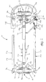
- FIG. 1 is a perspective view of a rail puller embodying the invention.
- FIG. 2 is a plan view of the rail puller of FIG. 1 in an open condition.
- FIG. 3 is a plan view of the rail puller of FIG. 1 in a closed condition.
- FIG. 4 is a cross-sectional view taken along line 4 - 4 of FIG. 3.
- FIG. 5 is an elevation view of the rail puller of FIG. 1.
- FIG. 6 is a plan view of the rail puller of FIG. 1, including a schematic of a hydraulic circuit.
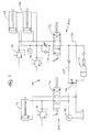
- FIG. 7 is a schematic of a hydraulic circuit for the rail puller of FIG. 1.
- FIG. 1 illustrates a rail puller 10 for tensioning rails and reducing the gap between the ends of rail sections.
- the rail puller 10 generally has a longitudinal direction along its length and a lateral direction across its width.
- the rail puller 10 comprises a first clamp assembly 14 and a second clamp assembly 18 disposed at opposite ends of the rail puller 10 .
- a clamping beam 22 and at least two pulling members 26 are coupled to the first and second clamp assemblies 14 , 18 .
- the clamping beam 22 extends longitudinally between the clamp assemblies 14 , 18 near the middle of the rail puller 10
- the pulling members 26 extend longitudinally between the clamp assemblies 14 , 18 along the sides of the rail puller 10 parallel and spaced apart from each other and from the clamping beam 22 .
- the pulling members 26 are coupled to the clamp assemblies 14 , 18 near the outer ends of the swing arms 34 .
- the pulling members 26 are pivotally coupled to the swing arms 34 at outer joints 46 , which are disposed laterally outwardly from the inner joints 38 .
- the swing arms 34 are generally triangular, with the inner joints 38 , outer joints 46 and grips 42 as the corners of the triangle. Movement of the inner joints 38 or outer joints 46 causes the swing arms 34 to pivot and move the grips 42 toward or away from the rail.
- the clamping beam 22 extends between the first clamp assembly 14 and the second clamp assembly 18 .
- the clamping beam 22 has a detachable end 50 that is removably coupled to the first clamp assembly 14 , and a pivot end 54 that is pivotally coupled to the second clamp assembly 18 .
- the detachable end 50 is removably coupled to a mounting bracket 58 on the first clamp assembly 14 with a lock pin 62 .
- the detachable end 50 and the mounting bracket 58 have lock holes 66 , and the lock pin 62 is inserted through the lock holes 66 to couple the clamping beam 22 to the first clamp assembly 14 .
- the lock pin 62 is removed from the lock holes 66 to disconnect the clamping beam 22 from the first clamp assembly 14 .
- the pivot end 54 is pivotally coupled with a pivot pin 74 to a mounting bracket 70 on the second clamp assembly 18 .
- the clamping beam 22 may be pivoted upwardly about the pivot pin 72 .
- the clamping beam 22 may then be pivoted downwardly and the detachable end 50 reconnected to the first clamp assembly 14 .
- the clamping beam 22 is pivoted to provide access to the rail sections and clearance within the rail puller 10 .
- the detachable end 50 and pivot end 54 of the clamping beam 22 could be reversed with the detachable end 50 removably coupled to the second clamp assembly 18 and the pivot end 54 coupled to the first clamp assembly 14 .
- the clamping beam 22 could be rigidly attached to the first clamp assembly 14 and second clamp assembly 18 to prevent the clamping beam 22 from pivoting.
- the clamping beam 22 includes a clamping cylinder 78 that adjusts the length of the clamping beam 22 .
- the clamping cylinder 78 extends to increase the length of the clamping beam 22 , or retracts to decrease the length of the clamping beam 22 .
- the clamping cylinder 78 is a hydraulic cylinder and includes a piston 82 and a housing 86 .
- a first portion 90 of the clamping beam 22 is interconnected to the piston 82 and a second portion 94 of the clamping beam 22 is interconnected to the housing 86 .
- the detachable end 50 is interconnected to the first portion 90 and the piston 82
- the pivot end 54 is interconnected to the second portion 94 and the housing 86 .
- the piston 82 creates a seal with the housing 86 , and a hydraulic circuit 98 provides hydraulic fluid to the clamping cylinder 78 to move the piston 82 in an extend direction or a retract direction with respect to the housing 86 to lengthen or shorten the clamping beam 22 .
- the length of the clamping beam 22 determines the distance between the clamp brackets 30 . Shortening the clamping beam 22 decreases the distance between the clamp brackets 30 , and lengthening the clamping beam 22 increases the distance between the clamp brackets 30 .
- the swing arms 34 are coupled to the clamp brackets 30 at the inner joints 38 .
- the pulling members 26 are similar to each other, and each pulling member 26 has a pulling cylinder 102 that adjusts the length of the pulling member 26 .
- the pulling cylinders 102 extend to increase the length of the pulling members 26 , or retract to decrease the length of the pulling members 26 .
- the pulling cylinders 102 are hydraulic cylinders, and each pulling cylinder 102 includes a piston 106 and a housing 110 .
- a first portion 114 of the pulling member 26 is interconnected to the piston 106 and a second portion 118 of the pulling member 26 is interconnected to the housing 110 .
- the first portions 114 are interconnected to one of the swing arms 34 of the first clamp assembly 14
- the second portions 118 are interconnected to one of the swing arms 34 of the second clamp assembly 18 .
- the pistons 106 create a seal with the housings 110 , and the hydraulic circuit 98 provides hydraulic fluid to the pulling cylinders 102 to move the pistons 106 in an extend direction or a retract direction with respect to the housings 110 to lengthen or shorten the pulling members 26 .
- the length of the pulling members 26 determines the distance between the outer joints 46 of the first clamp assembly 14 and the outer joints 46 of the second clamp assembly 18 . Shortening the pulling members 26 decreases the distance between the outer joints 46 , and lengthening the pulling members 26 increases the distance between the outer joints 46 .
- the hydraulic circuit 98 directs hydraulic fluid to extend or retract the clamping cylinder 78 and the pulling cylinders 102 .
- the hydraulic circuit 90 includes a power source 122 , a pump 124 , a controller 126 , an advance circuit 130 , and a retract circuit 134 .
- the power source 122 is a reservoir that provides hydraulic fluid for the hydraulic circuit 90 .
- the pump generates fluid flow through the hydraulic circuit 98 .
- the controller 126 is a valve that controls the flow of hydraulic fluid from the power source 122 to the advance circuit 130 or retract circuit 134 .
- the controller 126 generally has three settings: an extend or advance setting, a retract or pull setting, and a neutral setting.
- the advance circuit 130 extends or advances the clamping cylinder 78 and pulling cylinders 102 to lengthen the clamping beam 22 and pulling members 26 respectively.
- the retract circuit 134 retracts or pulls the clamping cylinder 78 and pulling cylinders 102 to shorten the clamping beam 22 and pulling members 26 respectively.
- the hydraulic circuit 98 also includes at least one shut-off valve 138 to control the flow of hydraulic fluid to the clamping cylinder 78 and the pulling cylinders 102 .
- the clamping cylinder 78 and pulling cylinders 102 are hydraulic cylinders, and the hydraulic circuit 98 is used to control the rail puller 10 .
- a pneumatic system, or other similar actuating devices could be used to actuate the clamping beam 22 and pulling members 26 to reduce the gap between rail sections.
- the rail puller 10 reduces the gap between the ends of rail sections. In order to reduce the gap, the clamp assemblies 14 , 18 clamp the rail sections, and the clamp assemblies 14 , 18 are then drawn closer together to pull the rail sections closer together. Generally, the clamping beam 22 is used to clamp the clamp assemblies 14 , 18 onto the rail sections, and the pulling members 26 are used to pull the clamp assemblies 14 , 18 and rail sections together.
- Hydraulic cylinders generally comprise a piston enclosed within a housing.
- the pulling capacity of the cylinder generally represents the amount of force the cylinder can generate, and is related to the diameter of the cylinder and the surface area of the piston in the cylinder.
- the travel distance of the cylinder generally represents the overall range and length of the cylinder, and is the distance between the fully retracted cylinder and the fully extended cylinder. The travel distance is related to the length of the housing.
- the weight and the cost of the cylinder also increase.
- the force required to draw the rail sections together is significantly greater than the force required to initiate the clamping of the rail sections.
- the clamping cylinder 78 clamps the rail sections, and the pulling cylinders 102 draw the rail sections together.
- the pulling cylinders 102 have a pulling capacity significantly greater than the pulling capacity of the clamping cylinder 78 .
- the clamping cylinder 78 is a double acting hydraulic cylinder with a capacity of approximately 10 tons on the extend or push side and approximately 4 tons on the pull side, and a travel distance of approximately 10 inches.
- the pulling cylinders 102 are double acting hydraulic cylinders with a capacity of approximately 60 tons on the pull side, and a travel distance of approximately 6 inches.
- the rail puller 10 uses the relatively smaller capacity clamping cylinder 78 to set and clamp the rail sections and reduce the necessary travel distance of the relatively larger capacity pulling cylinders 102 . Since the length of the larger pull capacity pulling cylinders 102 is decreased, the weight and cost of the pulling cylinders 102 are also decreased.
- the required travel path for cylinders of a rail puller can generally be divided into a clamping path and a pulling path.
- the pulling cylinders travel a clamping path of approximately 10 inches, and a pulling path of approximately 6 inches. Therefore, each pulling cylinder would require a total travel distance of approximately 16 inches.
- a single clamping cylinder 78 is used to clamp the rail sections and actuate the rail puller 10 through the clamping path which requires a relatively smaller force.
- the pulling cylinders 102 are only needed for the pulling path, which requires a relatively larger force in comparison to the clamping path. Therefore, in the illustrated embodiment, the travel distance of the pulling cylinders 102 may be reduced from the travel distance of prior art pulling cylinders. Using the previous example, the travel distance could be reduced approximately 10 inches. The reduction in travel distance of the pulling cylinders 102 reduces the weight and cost of the rail puller 10 .
- the clamping cylinder 78 has a smaller diameter than the pulling cylinder 102
- the piston 82 of the clamping cylinder 78 has a smaller exposed surface area than the pistons 106 of the pulling cylinders 102 .
- capacity is related to the diameter and exposed surface area of the pistons 82 , 106 .
- the capacity of the clamping cylinder 78 is significantly less than the capacity of the pulling cylinders 102 .
- the weight and cost savings from reducing the travel distance of the pulling cylinders 102 is significantly larger than the additional weight and cost of the clamping cylinder 78 . Therefore, the overall weight and cost of the rail puller 10 is less than the weight and cost of some prior art rail pullers.
- FIGS. 1, 3 and 4 illustrate the rail puller 10 in the open condition
- FIGS. 2 and 6 illustrate the rail puller 10 in the closed condition.
- the grips 42 are pivoted away from one another, and away from the rail sections.
- the clamping cylinder 78 is retracted, and the pulling cylinders 102 are extended.
- the clamping cylinder 78 extends to move the rail puller 10 from the open condition to the closed condition.
- FIG. 6 illustrates the rail puller 10 in the open condition with the hydraulic circuit 98 .
- the hydraulic circuit 98 includes the advance circuit 130 that extends the cylinders 78 , 102 , the retract circuit 134 that retracts the cylinders, and shut-off valves 138 that restrict the flow through the hydraulic circuit 98 .
- the controller 126 is adjusted to permit flow through the advance circuit 130 and extend the cylinders 78 , 102 . Since the pulling cylinders 102 are already extended, they will remain extended while the clamping cylinder 78 also extends.
- the clamping beam 22 increases in length and the clamp brackets 30 move away from one another in a longitudinally outward direction.
- the clamp brackets 30 and the inner joints 38 of the respective clamp assemblies 14 , 18 move away from one another, but the distance between the outer joints 46 of the respective clamp assemblies 14 , 18 remains substantially the same, which causes the swing arms 34 to pivot.
- the pivoting swing arms 34 move the grips 42 laterally inward toward the rail sections. As the swing arms 34 continue to pivot, the grips 42 engage the rail sections, and the clamp assemblies 14 , 18 clamp the rail sections.
- FIG. 4 illustrates the first clamp assembly 14 in the closed condition clamping the rail section A with the engaging surfaces 140 of the grips 42 contacting the rail section A.
- the swing arms 34 are opposed and rotate toward each other when pulling force is applied to the pulling members 26 by the pulling cylinders 102 .
- the clamping force developed by the clamp assemblies 14 , 18 is a ratio of the pulling force applied by the pulling cylinders 102 and is dependent on the ratio of the distance from the center line of the grips 42 , to the center line of the inner joints 38 , and the distance from the center line of the outer joints 46 to the center line of the inner joints 38 .
- the ratio can be varied as required to insure sufficient clamping pressure on the grips 42 to make them bite and hold the rail sections A and B.
- the hydraulic circuit 98 includes a priority valve 160 to control the extend sequence of the pulling cylinders 102 and the clamping cylinder 78 such that the pulling cylinders 102 always extend to their maximum travel before the clamping cylinder 78 extends the beam 22 to close the clamp assemblies 14 , 18 .
- the priority valve 160 also includes spring biased check valves 164 , 168 to provide a resistance to flow in and out of the extend port of clamping cylinder 78 .
- the resistance to flow provided by valve 164 of priority valve 160 insures full extension of the pulling cylinders 102 before extension of cylinder 78 of beam 22 to close the clamp assemblies 14 , 18 .
- the resistance to flow provided by valve 168 of priority valve 160 requires the retract circuit 134 to build and maintain sufficient pressure in the pulling cylinders 102 to keep the clamp assemblies 14 , 18 closed on the rail sections A and B while retracting the beam 22 .
- the lock pin 62 may be removed from the detachable end 50 to unlock the clamping beam 22 from the first clamp assembly 14 .
- the clamping cylinder 78 has a smaller cross-sectional area than the pulling cylinders 102 , and travels at a faster rate than the pulling cylinders 102 . Therefore, the clamping beam 78 is disengaged from the first clamp assembly 14 to prevent the clamp brackets 30 and the inner joints 38 from moving longitudinally inward at a faster rate than the outer joints 46 , which could cause the swings arms 34 to pivot the grips 42 outward and disengage the rail sections A, B. Removing the lock pin 62 ensures that the clamp assemblies 14 , 18 will not unclamp from the rail sections A, B while the rail puller 10 is pulling the rail sections A, B.
- the controller 126 is switched to a pull position and fluid flows into the retract circuit 134 to retract the cylinders 78 , 102 .
- the hydraulic circuit of beam 22 is protected by the priority valve 160 to limit the loading and control the retraction of the beam 22 .
- the spring biased valve 168 provides resistance to close the beam 22 .
- the priority valve 160 will force the puller 10 to first try to pull the rail before the beam 22 can disconnect from the clamp assemblies 14 , 18 . This action helps the puller 10 set itself on the rail before the beam 22 retracts.
- the full operating pressure of the hydraulic circuit 98 can be supplied to the pulling cylinders 102 to develop the force required to pull the rail.
- the priority valve 160 insures that the beam 22 retracts before the pulling cylinders 102 .
- the hydraulic pressure required to pull the rail sections A and B together is greater than the pressure required to retract the clamping cylinder 78 of beam 22 .
- the lock pin 62 is removed to disconnect the clamping beam 22 from the first clamp assembly 14 .
- the retracting pulling cylinders 102 pull the clamp assemblies 14 , 18 toward one another.
- the pulling cylinders 102 generally operate in unison to pull the rail sections together. Since the clamp assemblies 14 , 18 are clamped onto the rail sections A, B, the retracting pulling cylinders 102 also pull the rail sections A, B toward one another and reduce the gap between the rail sections A, B.
- a spring 142 biases the clamping beam 22 toward the pivoted position to reduce the amount of effort required to lift and pivot the clamping beam 22 .
- the spring 142 does not provide enough force to lift the clamping beam 22 independently, but it does provide assistance for lifting and pivoting the clamping beam 22 .
- the clamping beam 22 also includes handles 146 along the sides of clamping beam 22 to help a person lift and pivot the clamping beam 22 .
- the lock pin 62 may be inserted into a retaining hole 148 at the pivot end 54 near the pivot pin 74 . The lock pin 62 in the retaining hole 148 prevents the clamping beam 22 from unexpectedly pivoting downwardly before the welding activities are completed.
- the cylinders 78 , 102 may be located at any position along the clamping beam 22 and pulling members 26 .
- the clamping cylinder 78 is located near the pivot pin 74 and the second clamp assembly 18 . Since the clamping cylinder 78 generally weighs more than the remaining portion of the clamping beam 22 , locating the clamping cylinder 78 near the pivot end 54 lowers the center of gravity of the clamping beam 22 as it pivots and reduces the amount of effort required to pivot the clamping beam 22 upward.
- the pulling cylinders 102 are located near second clamp assembly 18 to minimize the amount of piping or hoses required for the hydraulic circuit 98 to connect the pulling cylinders 102 and clamping cylinder 78 .
- the rail puller 10 is moved to the open condition and removed from the rail sections.
- the controller 126 (FIG. 6) is moved to the extend position to release the clamping pressure.
- the lock pin 62 is removed from the retaining hole 148 and the clamping beam 22 is pivoted downwardly.
- the clamping cylinder 78 is extended until the clamping beam 22 can reengage with the first clamp assembly 14 and the lock pin 62 is inserted through the lock holes 66 to couple the detachable end 50 to the mounting bracket 58 .
- the pulling cylinders 102 continue to extend until they reach the maximum extended travel. After the pulling cylinders 102 are extended, the shut-off valves 138 are closed to prevent flow to the pulling cylinders 102 , and the controller 126 (FIG. 6) is moved to the retract position.
- the clamping cylinder 78 retracts to shorten the clamping beam 22 and move the clamp brackets 30 toward one another. As the clamp brackets 30 and inner joints 38 move longitudinally inward, the pulling members 26 maintain their length because the shut-off valves 138 prevent the retract circuit 134 from retracting the pulling cylinders 102 .
- the distance between the outer joints 46 of the first clamp assembly 14 and the outer joints 46 of the second clamp assembly 18 remains substantially the same.
- the rail puller 10 has hooks 150 on the clamping beam 22 to facilitate removing the rail puller 10 from the rail sections.
- a sling 154 is connected to the hooks 150 to help lift the rail puller 10 .
- the lock pin 62 is inserted through the lock holes 66 before the rail puller 10 is lifted.
- a crane, hoist, pulley system or other similar lifting device may be attached to the sling to lift the rail puller 10 and remove the rail puller 10 from the rail sections.
- FIG. 7 illustrates an additional embodiment of the hydraulic circuit 98 having an advance circuit 130 and retract circuit 134 .
- the hydraulic circuit 98 includes a pull control valve 172 that controls the pulling cylinders 102 , and a beam control valve 176 that controls the clamping cylinder 78 .
- the control valves 172 , 176 may be used to operate the cylinders 78 , 102 independently.
- the hydraulic circuit 98 also includes at least one relief valve 180 . In the illustrated embodiment, each cylinder 78 , 102 is in fluid flow communication with a relief valve 180 .
- the hydraulic circuit 98 also includes a load lock valve 184 and a speed control valve 188 .
- the load lock valve 184 may include a needle valve to regulate flow in a first direction and a check valve to regulate flow in a second direction.
- the speed control valve 188 regulates the speed of fluid flow through the hydraulic circuit 98 and may include a needle valve.
- the hydraulic circuit 98 includes a power connection 192 that may be connected to a power take off unit (PTO) on a railway vehicle or other power source.
- PTO power take off unit
- Railway vehicles commonly include a PTO to provide power, such as hydraulic power, for auxiliary equipment, such as a rail puller.
- the PTO may provide hydraulic flow to the hydraulic circuit 98 at approximately 5 to 10 GPM (gallons per minute) and 2000 PSI (pounds per square inch).
- a hydraulic booster 196 may increase the pressure of the hydraulic flow through at least a portion of the hydraulic circuit 98 .
- the hydraulic booster 196 may increase the pressure of the 5-10 GPM at 2000 PSI fluid flow to approximately 1-2 GPM at 10,000 PSI.
- the hydraulic circuit 98 may include a low pressure portion 200 having the lower pressure fluid flow input from the PTO, and a high pressure portion 204 having a higher pressure fluid flow from the hydraulic booster 196 .
- the beam control valve 176 controls the clamping cylinder 78 on the low pressure portion 200
- the pull control valve 176 controls the pulling cylinders 102 on the high pressure portion 204 .
- the increased pressure on the high pressure portion 204 may be used to generate a higher pulling force in the pulling cylinders 102 .
Landscapes
- Engineering & Computer Science (AREA)
- Architecture (AREA)
- Civil Engineering (AREA)
- Structural Engineering (AREA)
- Carriers, Traveling Bodies, And Overhead Traveling Cranes (AREA)
- Machines For Laying And Maintaining Railways (AREA)
- Accommodation For Nursing Or Treatment Tables (AREA)
Abstract
Description
- This invention relates to rail pullers, and more particularly to hydraulic clamping rail pullers used to tension rails.
- Rail pullers are commonly used in railways to pull the ends of rail sections together. Rail sections are relatively long, and may be as long as one quarter mile. The rail sections are usually aligned linearly with a gap between the ends of the rail sections. The gap between the rail sections may be approximately 6 inches. The rail puller puts the rail sections in tension to reduce the gap between the rail sections. Once the rail sections are pulled together, the ends of the rail sections are welded together to form a continuous track.
- Rail sections are relatively heavy, and the force required to pull rail sections together and reduce the gap between the rail section is relatively large. Some prior art rail pullers use rams or hydraulic cylinders to pull the rail sections together. The hydraulic cylinders needed to generate the relatively large force required to pull the rail sections together are relatively heavy and expensive. Two characteristics of hydraulic cylinders are the travel distance and the pull capacity of the cylinder. The travel distance is dependent upon the length of the cylinder, and determines the distance between the fully retracted cylinder to the fully extended cylinder. The pull capacity is related to the cross-sectional area of the cylinder, and determines the amount of force the cylinder can generate.
- Rail pullers generally clamp the rail sections, and then pull the rail sections together. The force required to clamp the rail sections is significantly less than the force required to pull the rail sections together. In some prior art rail pullers, the same hydraulic cylinders are used to both clamp the rail sections and pull the rail sections together.
- The rail puller embodying the invention applies tension to rail sections to reduce the gap between the ends of rail sections. The rail puller comprises a first clamp assembly at one end of the rail puller, and a second clamp assembly at the opposite end of the rail puller. An elongated clamping beam is coupled to the first clamp assembly and the second clamp assembly, and includes a clamping cylinder that is extendable and retractable to adjust the length of the clamping beam. Elongated pulling members are coupled to the first clamp assembly and the second clamp assembly, and each pulling member has a pulling cylinder that is extendable and retractable to adjust the length of the pulling member. The clamping cylinder extends to position and clamp the first clamp assembly and second clamp assembly to rail sections, and the pulling cylinders retract to draw the first clamp assembly and second clamp assembly toward one another and reduce the gap between the rail sections.
- The rail puller minimizes the travel distance of hydraulic cylinders used to pull the rail sections together. The clamping cylinder extends to lengthen the clamping beam and clamp the clamp assemblies onto the rail sections. Once the rail sections have been clamped, the pulling cylinders retract to pull the rail sections together. The travel distance of the pulling cylinders is reduced because the clamping cylinder is used to clamp the rail sections. Since the travel distance of the pulling cylinders is reduced, the weight and cost of the pulling cylinders is also reduced.
- The force required to position the clamp assemblies clamp the rail sections is significantly less than the force required to pull the rail sections together, and the pulling capacity of the clamping cylinder can be substantially less than the pulling capacity of the pulling cylinders. Additionally, a single clamping cylinder can be used to clamp the rail sections. Since the pulling capacity of the clamping cylinder can be less than the required pulling capacity of the pulling cylinders, the overall weight and cost of the rail puller can be minimized.
- FIG. 1 is a perspective view of a rail puller embodying the invention.
- FIG. 2 is a plan view of the rail puller of FIG. 1 in an open condition.
- FIG. 3 is a plan view of the rail puller of FIG. 1 in a closed condition.
- FIG. 4 is a cross-sectional view taken along line 4-4 of FIG. 3.
- FIG. 5 is an elevation view of the rail puller of FIG. 1.
- FIG. 6 is a plan view of the rail puller of FIG. 1, including a schematic of a hydraulic circuit.
- FIG. 7 is a schematic of a hydraulic circuit for the rail puller of FIG. 1.
- Before the embodiments of the invention are explained in detail, it is to be understood that the invention is not limited in its application to the details of construction and the arrangements of components set forth in the following description or illustrated in the drawings. The invention is capable of other embodiments and of being practiced or of being carried out in various ways. Also, it is to be understood that the phraseology and terminology used herein is for the purpose of description and should not be regarded as limiting.
- Although references are made below to directions, such as left, right, up, down, top, bottom, front, rear, back etc., in describing the drawings, they are made relative to the drawings (as normally viewed) for convenience. These directions are not intended to be taken literally or limit the present invention in any form.
- FIG. 1 illustrates a
rail puller 10 for tensioning rails and reducing the gap between the ends of rail sections. Therail puller 10 generally has a longitudinal direction along its length and a lateral direction across its width. Therail puller 10 comprises afirst clamp assembly 14 and asecond clamp assembly 18 disposed at opposite ends of therail puller 10. Aclamping beam 22 and at least two pullingmembers 26 are coupled to the first andsecond clamp assemblies clamping beam 22 extends longitudinally between theclamp assemblies rail puller 10, and thepulling members 26 extend longitudinally between theclamp assemblies rail puller 10 parallel and spaced apart from each other and from theclamping beam 22. - In the illustrated embodiment, the
clamp assemblies clamp assembly clamp bracket 30 and twoswing arms 34. Theswing arms 34 are pivotally coupled to theclamp bracket 30 atinner joints 38. Eachswing arm 34 has agrip 42 disposed longitudinally inwardly from theinner joint 38 near the inner side of theclamp assembly opposing clamp assembly grips 42 are pivotally coupled to theswing arms 34. - The
clamping beam 22 is coupled to theclamp assemblies clamp brackets 30. Theclamp brackets 30 generally extend in a lateral direction and are substantially transverse to theclamping beam 22. As shown in FIG. 4, theclamp brackets 30 are curved and generally C-shaped with the curved opening near the bottom portion of theclamp bracket 30 to provide clearance for a rail section A. Theinner joints 38 coupling theclamp bracket 30 and theswing arms 34 are near the ends of theclamp bracket 30. - In FIG. 1, the pulling
members 26 are coupled to theclamp assemblies swing arms 34. The pullingmembers 26 are pivotally coupled to theswing arms 34 atouter joints 46, which are disposed laterally outwardly from theinner joints 38. Theswing arms 34 are generally triangular, with theinner joints 38,outer joints 46 andgrips 42 as the corners of the triangle. Movement of theinner joints 38 orouter joints 46 causes theswing arms 34 to pivot and move thegrips 42 toward or away from the rail. - The
clamping beam 22 extends between thefirst clamp assembly 14 and thesecond clamp assembly 18. In the illustrated embodiment, theclamping beam 22 has adetachable end 50 that is removably coupled to thefirst clamp assembly 14, and apivot end 54 that is pivotally coupled to thesecond clamp assembly 18. Thedetachable end 50 is removably coupled to a mountingbracket 58 on thefirst clamp assembly 14 with alock pin 62. Thedetachable end 50 and the mountingbracket 58 have lock holes 66, and thelock pin 62 is inserted through the lock holes 66 to couple theclamping beam 22 to thefirst clamp assembly 14. Thelock pin 62 is removed from the lock holes 66 to disconnect theclamping beam 22 from thefirst clamp assembly 14. - The
pivot end 54 is pivotally coupled with apivot pin 74 to a mountingbracket 70 on thesecond clamp assembly 18. When thedetachable end 50 is disconnected from thefirst clamp assembly 14, theclamping beam 22 may be pivoted upwardly about the pivot pin 72. Theclamping beam 22 may then be pivoted downwardly and thedetachable end 50 reconnected to thefirst clamp assembly 14. As described below, theclamping beam 22 is pivoted to provide access to the rail sections and clearance within therail puller 10. Alternatively, thedetachable end 50 and pivot end 54 of theclamping beam 22 could be reversed with thedetachable end 50 removably coupled to thesecond clamp assembly 18 and thepivot end 54 coupled to thefirst clamp assembly 14. Additionally, theclamping beam 22 could be rigidly attached to thefirst clamp assembly 14 andsecond clamp assembly 18 to prevent theclamping beam 22 from pivoting. - The
clamping beam 22 includes aclamping cylinder 78 that adjusts the length of theclamping beam 22. The clampingcylinder 78 extends to increase the length of theclamping beam 22, or retracts to decrease the length of theclamping beam 22. As shown in FIG. 6, the clampingcylinder 78 is a hydraulic cylinder and includes apiston 82 and ahousing 86. Afirst portion 90 of theclamping beam 22 is interconnected to thepiston 82 and asecond portion 94 of theclamping beam 22 is interconnected to thehousing 86. In FIG. 6, thedetachable end 50 is interconnected to thefirst portion 90 and thepiston 82, and thepivot end 54 is interconnected to thesecond portion 94 and thehousing 86. - The
piston 82 creates a seal with thehousing 86, and ahydraulic circuit 98 provides hydraulic fluid to theclamping cylinder 78 to move thepiston 82 in an extend direction or a retract direction with respect to thehousing 86 to lengthen or shorten theclamping beam 22. The length of theclamping beam 22 determines the distance between theclamp brackets 30. Shortening theclamping beam 22 decreases the distance between theclamp brackets 30, and lengthening theclamping beam 22 increases the distance between theclamp brackets 30. As mentioned above, theswing arms 34 are coupled to theclamp brackets 30 at theinner joints 38. - In the illustrated embodiment, the pulling
members 26 are similar to each other, and each pullingmember 26 has a pullingcylinder 102 that adjusts the length of the pullingmember 26. The pullingcylinders 102 extend to increase the length of the pullingmembers 26, or retract to decrease the length of the pullingmembers 26. As shown in FIG. 6, the pullingcylinders 102 are hydraulic cylinders, and each pullingcylinder 102 includes apiston 106 and ahousing 110. Afirst portion 114 of the pullingmember 26 is interconnected to thepiston 106 and asecond portion 118 of the pullingmember 26 is interconnected to thehousing 110. In the illustrated embodiment, thefirst portions 114 are interconnected to one of theswing arms 34 of thefirst clamp assembly 14, and thesecond portions 118 are interconnected to one of theswing arms 34 of thesecond clamp assembly 18. - The
pistons 106 create a seal with thehousings 110, and thehydraulic circuit 98 provides hydraulic fluid to the pullingcylinders 102 to move thepistons 106 in an extend direction or a retract direction with respect to thehousings 110 to lengthen or shorten the pullingmembers 26. The length of the pullingmembers 26 determines the distance between theouter joints 46 of thefirst clamp assembly 14 and theouter joints 46 of thesecond clamp assembly 18. Shortening the pullingmembers 26 decreases the distance between theouter joints 46, and lengthening the pullingmembers 26 increases the distance between the outer joints 46. As described below, when theclamp assemblies cylinders 102 and shortening the pullingmembers 26 draws theclamp assemblies cylinders 102 usually operate together in unison. - As shown in FIG. 6, the
hydraulic circuit 98 directs hydraulic fluid to extend or retract theclamping cylinder 78 and the pullingcylinders 102. In the illustrated embodiment, thehydraulic circuit 90 includes apower source 122, apump 124, acontroller 126, anadvance circuit 130, and a retractcircuit 134. Thepower source 122 is a reservoir that provides hydraulic fluid for thehydraulic circuit 90. The pump generates fluid flow through thehydraulic circuit 98. Thecontroller 126 is a valve that controls the flow of hydraulic fluid from thepower source 122 to theadvance circuit 130 or retractcircuit 134. Thecontroller 126 generally has three settings: an extend or advance setting, a retract or pull setting, and a neutral setting. Theadvance circuit 130 extends or advances theclamping cylinder 78 and pullingcylinders 102 to lengthen theclamping beam 22 and pullingmembers 26 respectively. The retractcircuit 134 retracts or pulls the clampingcylinder 78 and pullingcylinders 102 to shorten theclamping beam 22 and pullingmembers 26 respectively. Thehydraulic circuit 98 also includes at least one shut-offvalve 138 to control the flow of hydraulic fluid to theclamping cylinder 78 and the pullingcylinders 102. - In the illustrated embodiment, the clamping
cylinder 78 and pullingcylinders 102 are hydraulic cylinders, and thehydraulic circuit 98 is used to control therail puller 10. Alternatively, a pneumatic system, or other similar actuating devices could be used to actuate theclamping beam 22 and pullingmembers 26 to reduce the gap between rail sections. - The
rail puller 10 reduces the gap between the ends of rail sections. In order to reduce the gap, theclamp assemblies clamp assemblies clamping beam 22 is used to clamp theclamp assemblies members 26 are used to pull theclamp assemblies - Some prior art rail pullers have a single set of pulling cylinders that clamp the rail sections, as well as draw the rail sections together. Two important features of hydraulic cylinders are the pulling capacity and the travel distance of the cylinder. Hydraulic cylinders generally comprise a piston enclosed within a housing. The pulling capacity of the cylinder generally represents the amount of force the cylinder can generate, and is related to the diameter of the cylinder and the surface area of the piston in the cylinder. The travel distance of the cylinder generally represents the overall range and length of the cylinder, and is the distance between the fully retracted cylinder and the fully extended cylinder. The travel distance is related to the length of the housing. Generally, as the pulling capacity and travel distance of a cylinder increases, the weight and the cost of the cylinder also increase.
- The force required to draw the rail sections together is significantly greater than the force required to initiate the clamping of the rail sections. In the illustrated embodiment, the clamping
cylinder 78 clamps the rail sections, and the pullingcylinders 102 draw the rail sections together. The pullingcylinders 102 have a pulling capacity significantly greater than the pulling capacity of the clampingcylinder 78. In the illustrated embodiment, the clampingcylinder 78 is a double acting hydraulic cylinder with a capacity of approximately 10 tons on the extend or push side and approximately 4 tons on the pull side, and a travel distance of approximately 10 inches. The pullingcylinders 102 are double acting hydraulic cylinders with a capacity of approximately 60 tons on the pull side, and a travel distance of approximately 6 inches. - The
rail puller 10 uses the relatively smallercapacity clamping cylinder 78 to set and clamp the rail sections and reduce the necessary travel distance of the relatively largercapacity pulling cylinders 102. Since the length of the larger pullcapacity pulling cylinders 102 is decreased, the weight and cost of the pullingcylinders 102 are also decreased. - The required travel path for cylinders of a rail puller can generally be divided into a clamping path and a pulling path. For example, in some prior art rail pullers having only pulling cylinders, the pulling cylinders travel a clamping path of approximately 10 inches, and a pulling path of approximately 6 inches. Therefore, each pulling cylinder would require a total travel distance of approximately 16 inches.
- In the illustrated embodiment, a
single clamping cylinder 78 is used to clamp the rail sections and actuate therail puller 10 through the clamping path which requires a relatively smaller force. The pullingcylinders 102 are only needed for the pulling path, which requires a relatively larger force in comparison to the clamping path. Therefore, in the illustrated embodiment, the travel distance of the pullingcylinders 102 may be reduced from the travel distance of prior art pulling cylinders. Using the previous example, the travel distance could be reduced approximately 10 inches. The reduction in travel distance of the pullingcylinders 102 reduces the weight and cost of therail puller 10. - As shown in FIG. 6, the clamping
cylinder 78 has a smaller diameter than the pullingcylinder 102, and thepiston 82 of the clampingcylinder 78 has a smaller exposed surface area than thepistons 106 of the pullingcylinders 102. As mentioned above, capacity is related to the diameter and exposed surface area of thepistons cylinder 78 is significantly less than the capacity of the pullingcylinders 102. The weight and cost savings from reducing the travel distance of the pullingcylinders 102 is significantly larger than the additional weight and cost of the clampingcylinder 78. Therefore, the overall weight and cost of therail puller 10 is less than the weight and cost of some prior art rail pullers. - The
rail puller 10 is movable between an open condition and a closed condition. FIGS. 1, 3 and 4 illustrate therail puller 10 in the open condition, and FIGS. 2 and 6 illustrate therail puller 10 in the closed condition. When therail puller 10 is in the open condition, as shown in FIG. 2, thegrips 42 are pivoted away from one another, and away from the rail sections. In the open condition, the clampingcylinder 78 is retracted, and the pullingcylinders 102 are extended. The clampingcylinder 78 extends to move therail puller 10 from the open condition to the closed condition. - FIG. 6 illustrates the
rail puller 10 in the open condition with thehydraulic circuit 98. As mentioned above, thehydraulic circuit 98 includes theadvance circuit 130 that extends thecylinders circuit 134 that retracts the cylinders, and shut-offvalves 138 that restrict the flow through thehydraulic circuit 98. To move therail puller 10 to the closed condition, thecontroller 126 is adjusted to permit flow through theadvance circuit 130 and extend thecylinders cylinders 102 are already extended, they will remain extended while the clampingcylinder 78 also extends. - As the
clamping cylinder 78 extends, theclamping beam 22 increases in length and theclamp brackets 30 move away from one another in a longitudinally outward direction. Theclamp brackets 30 and theinner joints 38 of therespective clamp assemblies outer joints 46 of therespective clamp assemblies swing arms 34 to pivot. The pivotingswing arms 34 move thegrips 42 laterally inward toward the rail sections. As theswing arms 34 continue to pivot, thegrips 42 engage the rail sections, and theclamp assemblies - Once the clamping
cylinder 78 is extended and theclamp assemblies rail puller 10 is in the closed condition. FIG. 3 illustrates therail puller 10 in the closed condition clamping a first rail section A and a second rail section B. Thefirst clamp assembly 14 clamps the first rail section A, and thesecond clamp assembly 18 clamps the second rail section B. In the illustrated embodiment, thegrips 42 are pivotally coupled to theswing arms 34 to ensure that anengaging surface 140 properly aligns with the rail sections A, B. Thegrips 42 pivot with respect to theswing arms 34 to maximize contact between theengaging surface 140 and the rail sections A, B as theswing arms 34 pivot to the clamped closed condition. The pivoting grips 42 permit theclamp assemblies engaging surface 140. FIG. 4 illustrates thefirst clamp assembly 14 in the closed condition clamping the rail section A with the engagingsurfaces 140 of thegrips 42 contacting the rail section A. - The
swing arms 34 are opposed and rotate toward each other when pulling force is applied to the pullingmembers 26 by the pullingcylinders 102. The clamping force developed by theclamp assemblies cylinders 102 and is dependent on the ratio of the distance from the center line of thegrips 42, to the center line of theinner joints 38, and the distance from the center line of theouter joints 46 to the center line of theinner joints 38. The ratio can be varied as required to insure sufficient clamping pressure on thegrips 42 to make them bite and hold the rail sections A and B. - In FIG. 6, the
hydraulic circuit 98 includes a priority valve 160 to control the extend sequence of the pullingcylinders 102 and theclamping cylinder 78 such that the pullingcylinders 102 always extend to their maximum travel before the clampingcylinder 78 extends thebeam 22 to close theclamp assemblies check valves 164, 168 to provide a resistance to flow in and out of the extend port of clampingcylinder 78. The resistance to flow provided byvalve 164 of priority valve 160 insures full extension of the pullingcylinders 102 before extension ofcylinder 78 ofbeam 22 to close theclamp assemblies circuit 134 to build and maintain sufficient pressure in the pullingcylinders 102 to keep theclamp assemblies beam 22. - In FIG. 3, after the
clamp assemblies lock pin 62 may be removed from thedetachable end 50 to unlock theclamping beam 22 from thefirst clamp assembly 14. In the illustrated embodiment, the clampingcylinder 78 has a smaller cross-sectional area than the pullingcylinders 102, and travels at a faster rate than the pullingcylinders 102. Therefore, theclamping beam 78 is disengaged from thefirst clamp assembly 14 to prevent theclamp brackets 30 and theinner joints 38 from moving longitudinally inward at a faster rate than theouter joints 46, which could cause theswings arms 34 to pivot thegrips 42 outward and disengage the rail sections A, B. Removing thelock pin 62 ensures that theclamp assemblies rail puller 10 is pulling the rail sections A, B. - To pull the rail sections using the
hydraulic circuit 98 shown in FIG. 6, thecontroller 126 is switched to a pull position and fluid flows into the retractcircuit 134 to retract thecylinders beam 22 is protected by the priority valve 160 to limit the loading and control the retraction of thebeam 22. The spring biased valve 168 provides resistance to close thebeam 22. After thepin 62 is removed from thebeam 22, the priority valve 160 will force thepuller 10 to first try to pull the rail before thebeam 22 can disconnect from theclamp assemblies puller 10 set itself on the rail before thebeam 22 retracts. Once thebeam 22 retracts, the full operating pressure of thehydraulic circuit 98 can be supplied to the pullingcylinders 102 to develop the force required to pull the rail. By maintaining the initial clamping pressure, the priority valve 160 insures that thebeam 22 retracts before the pullingcylinders 102. - The hydraulic pressure required to pull the rail sections A and B together is greater than the pressure required to retract the
clamping cylinder 78 ofbeam 22. Thelock pin 62 is removed to disconnect theclamping beam 22 from thefirst clamp assembly 14. Theretracting pulling cylinders 102 pull theclamp assemblies cylinders 102 generally operate in unison to pull the rail sections together. Since theclamp assemblies retracting pulling cylinders 102 also pull the rail sections A, B toward one another and reduce the gap between the rail sections A, B. - After the
clamping beam 22 is retracted and the rail sections are pulled together, theclamping beam 22 may be pivoted upwardly about thepivot pin 74 to provide clearance for welding the rail sections together. FIG. 5 illustrates theclamping beam 22 in the substantially horizontal position coupled to thefirst clamp assembly 14. The dashed lines of FIG. 5 illustrate theclamping beam 22 in the upward pivoted position. With theclamping beam 22 pivoted upward, there is additional clearance near the middle of therail puller 10 to provide a clear workspace for welding the rail sections together. - A
spring 142 biases theclamping beam 22 toward the pivoted position to reduce the amount of effort required to lift and pivot theclamping beam 22. In the illustrated embodiment, thespring 142 does not provide enough force to lift theclamping beam 22 independently, but it does provide assistance for lifting and pivoting theclamping beam 22. Theclamping beam 22 also includeshandles 146 along the sides of clampingbeam 22 to help a person lift and pivot theclamping beam 22. After theclamping beam 22 is pivoted upward, thelock pin 62 may be inserted into a retaining hole 148 at thepivot end 54 near thepivot pin 74. Thelock pin 62 in the retaining hole 148 prevents theclamping beam 22 from unexpectedly pivoting downwardly before the welding activities are completed. - The
cylinders clamping beam 22 and pullingmembers 26. In the illustrated embodiment, the clampingcylinder 78 is located near thepivot pin 74 and thesecond clamp assembly 18. Since the clampingcylinder 78 generally weighs more than the remaining portion of theclamping beam 22, locating the clampingcylinder 78 near thepivot end 54 lowers the center of gravity of theclamping beam 22 as it pivots and reduces the amount of effort required to pivot theclamping beam 22 upward. Additionally, the pullingcylinders 102 are located nearsecond clamp assembly 18 to minimize the amount of piping or hoses required for thehydraulic circuit 98 to connect the pullingcylinders 102 and clampingcylinder 78. - After the ends of the rail sections are welded together, the
rail puller 10 is moved to the open condition and removed from the rail sections. First, the controller 126 (FIG. 6) is moved to the extend position to release the clamping pressure. Next, thelock pin 62 is removed from the retaining hole 148 and theclamping beam 22 is pivoted downwardly. The clampingcylinder 78 is extended until theclamping beam 22 can reengage with thefirst clamp assembly 14 and thelock pin 62 is inserted through the lock holes 66 to couple thedetachable end 50 to the mountingbracket 58. - The pulling
cylinders 102 continue to extend until they reach the maximum extended travel. After the pullingcylinders 102 are extended, the shut-offvalves 138 are closed to prevent flow to the pullingcylinders 102, and the controller 126 (FIG. 6) is moved to the retract position. The clampingcylinder 78 retracts to shorten theclamping beam 22 and move theclamp brackets 30 toward one another. As theclamp brackets 30 andinner joints 38 move longitudinally inward, the pullingmembers 26 maintain their length because the shut-offvalves 138 prevent the retractcircuit 134 from retracting the pullingcylinders 102. The distance between theouter joints 46 of thefirst clamp assembly 14 and theouter joints 46 of thesecond clamp assembly 18 remains substantially the same. The movement of theinner joints 38 with respect to theouter joints 46 causes theswing arms 34 to pivot and move thegrips 42 laterally outward and away from the rail sections. After theclamping cylinder 78 is retracted, therail puller 10 is once again in the open condition. - As shown in FIG. 5, the
rail puller 10 hashooks 150 on theclamping beam 22 to facilitate removing therail puller 10 from the rail sections. Asling 154 is connected to thehooks 150 to help lift therail puller 10. Thelock pin 62 is inserted through the lock holes 66 before therail puller 10 is lifted. A crane, hoist, pulley system or other similar lifting device may be attached to the sling to lift therail puller 10 and remove therail puller 10 from the rail sections. - FIG. 7 illustrates an additional embodiment of the
hydraulic circuit 98 having anadvance circuit 130 and retractcircuit 134. Thehydraulic circuit 98 includes apull control valve 172 that controls the pullingcylinders 102, and abeam control valve 176 that controls the clampingcylinder 78. Thecontrol valves cylinders hydraulic circuit 98 also includes at least onerelief valve 180. In the illustrated embodiment, eachcylinder relief valve 180. Thehydraulic circuit 98 also includes aload lock valve 184 and aspeed control valve 188. Theload lock valve 184 may include a needle valve to regulate flow in a first direction and a check valve to regulate flow in a second direction. Thespeed control valve 188 regulates the speed of fluid flow through thehydraulic circuit 98 and may include a needle valve. - In FIG. 7, the
hydraulic circuit 98 includes apower connection 192 that may be connected to a power take off unit (PTO) on a railway vehicle or other power source. Railway vehicles commonly include a PTO to provide power, such as hydraulic power, for auxiliary equipment, such as a rail puller. In the illustrated embodiment, the PTO may provide hydraulic flow to thehydraulic circuit 98 at approximately 5 to 10 GPM (gallons per minute) and 2000 PSI (pounds per square inch). - A
hydraulic booster 196 may increase the pressure of the hydraulic flow through at least a portion of thehydraulic circuit 98. Thehydraulic booster 196 may increase the pressure of the 5-10 GPM at 2000 PSI fluid flow to approximately 1-2 GPM at 10,000 PSI. In the illustrated embodiment, thehydraulic circuit 98 may include alow pressure portion 200 having the lower pressure fluid flow input from the PTO, and ahigh pressure portion 204 having a higher pressure fluid flow from thehydraulic booster 196. In FIG. 7, thebeam control valve 176 controls the clampingcylinder 78 on thelow pressure portion 200, and thepull control valve 176 controls the pullingcylinders 102 on thehigh pressure portion 204. The increased pressure on thehigh pressure portion 204 may be used to generate a higher pulling force in the pullingcylinders 102.
Claims (32)
Priority Applications (2)
| Application Number | Priority Date | Filing Date | Title |
|---|---|---|---|
| US10/127,385 US6637727B1 (en) | 2002-04-22 | 2002-04-22 | Rail puller including a clamping beam and two clamping members and a method thereof |
| CA2426435A CA2426435C (en) | 2002-04-22 | 2003-04-22 | Rail puller |
Applications Claiming Priority (1)
| Application Number | Priority Date | Filing Date | Title |
|---|---|---|---|
| US10/127,385 US6637727B1 (en) | 2002-04-22 | 2002-04-22 | Rail puller including a clamping beam and two clamping members and a method thereof |
Publications (2)
| Publication Number | Publication Date |
|---|---|
| US20030196565A1 true US20030196565A1 (en) | 2003-10-23 |
| US6637727B1 US6637727B1 (en) | 2003-10-28 |
Family
ID=29215254
Family Applications (1)
| Application Number | Title | Priority Date | Filing Date |
|---|---|---|---|
| US10/127,385 Expired - Lifetime US6637727B1 (en) | 2002-04-22 | 2002-04-22 | Rail puller including a clamping beam and two clamping members and a method thereof |
Country Status (2)
| Country | Link |
|---|---|
| US (1) | US6637727B1 (en) |
| CA (1) | CA2426435C (en) |
Cited By (6)
| Publication number | Priority date | Publication date | Assignee | Title |
|---|---|---|---|---|
| US20050252406A1 (en) * | 2004-05-17 | 2005-11-17 | Stian Nilsen | Device for lifting and re-positioning a track used in television and motion picture industries |
| CN100558986C (en) * | 2006-03-09 | 2009-11-11 | 南昌铁路局科学技术研究所 | The acclerating road switch and the section of track are changed or maintenance lifting method |
| ES2399759R1 (en) * | 2010-03-25 | 2013-05-14 | Administrador De Infraestructuras Ferroviarias Adif | HYDRAULIC TENSIONER TO RELEASE VOLTAGE ON RAILWAY ROADS |
| FR2998310A1 (en) * | 2012-11-16 | 2014-05-23 | Anciens Etablissements Lucien Geismar Soc D | ASSEMBLY FOR A CLAMPING DEVICE OF A RAIL TENSIONER |
| WO2014144739A1 (en) * | 2013-03-15 | 2014-09-18 | Harsco Corporation | Rail camp |
| US11613853B2 (en) * | 2017-07-04 | 2023-03-28 | Plasser & Theurer Export Von Bahnbaumaschinen Gmbh | Device for welding a rail joint of a track |
Families Citing this family (14)
| Publication number | Priority date | Publication date | Assignee | Title |
|---|---|---|---|---|
| AT501272B8 (en) * | 2005-03-30 | 2007-02-15 | Plasser Bahnbaumasch Franz | METHOD FOR REMOVING DAMAGED RAILWAYS OF A TRAIL AND MACHINE |
| DK1731673T3 (en) * | 2005-05-18 | 2008-05-26 | Plasser Bahnbaumasch Franz | Welding machine and method for welding rails in a track |
| ATE389750T1 (en) * | 2005-06-24 | 2008-04-15 | Plasser Bahnbaumasch Franz | WELDING MACHINE FOR WELDING RAILS OF A TRACK |
| RU2334038C1 (en) * | 2007-02-26 | 2008-09-20 | Государственное образовательное учреждение высшего профессионального образования "Петербургский государственный университет путей сообщения" | Railway track section pusher |
| WO2009114027A1 (en) * | 2008-03-12 | 2009-09-17 | Chemetron-Railway Products, Inc. | In-track rail welding system |
| US20110290766A1 (en) * | 2010-05-28 | 2011-12-01 | Battisti Charles R | System and method for flash-welding |
| US9121140B2 (en) | 2011-02-09 | 2015-09-01 | Robert B. Conner, Jr. | Low profile material handling system |
| US10571135B2 (en) | 2012-04-09 | 2020-02-25 | David Kreutzman | Renewable energy hot water heater with heat pump |
| DE202015006320U1 (en) | 2015-09-05 | 2015-10-23 | Robel Bahnbaumaschinen Gmbh | Rail pulling device |
| CN107116669B (en) * | 2017-06-30 | 2023-09-19 | 中交第一航务工程局有限公司 | Automatic template supporting and disassembling equipment for king-twisting character blocks |
| CN107165007A (en) * | 2017-07-20 | 2017-09-15 | 姜健民 | Gapless track destressing hydraulic pressure automatic rail collision machine |
| CN110359489B (en) * | 2019-07-03 | 2024-04-26 | 鞍山三冶建筑工程有限公司 | A large prefabricated pipe gallery top-pushing construction structure |
| CN110359491B (en) * | 2019-07-03 | 2024-04-26 | 鞍山三冶建筑工程有限公司 | A translation device for installing a large prefabricated pipe gallery |
| CN112442928B (en) * | 2019-08-30 | 2025-11-04 | 张伟 | A hydraulic track lifter and its usage method |
Family Cites Families (20)
| Publication number | Priority date | Publication date | Assignee | Title |
|---|---|---|---|---|
| US3424101A (en) | 1965-03-04 | 1969-01-28 | Frederick L Striebel | Method for transposing railroad track rails |
| US3465687A (en) | 1966-11-18 | 1969-09-09 | New York Central Railroad Co T | Rail positioning system |
| US3635164A (en) | 1969-12-29 | 1972-01-18 | Robert W Patton | Rail-transposing machine |
| US3670912A (en) * | 1970-03-16 | 1972-06-20 | Glenn G Dunbar | Container handling apparatus |
| US3731635A (en) | 1971-08-09 | 1973-05-08 | Trakwork Equipment Co | Rail pulling apparatus |
| AU517045B2 (en) | 1977-07-08 | 1981-07-02 | C. Delachaux SA | Aligning and setting gap between rails |
| FR2447421A2 (en) | 1979-01-24 | 1980-08-22 | Delachaux C | DEVICE FOR ADJUSTING THE ALIGNMENT AND THE INTERSECTION DISTANCE OF TWO END OF TRACKS |
| FR2450904A1 (en) | 1979-03-05 | 1980-10-03 | Delachaux Sa C | DEVICE FOR ADJUSTING TWO END OF TRACKS TO BE CONNECTED BY WELDING |
| FR2456810A1 (en) | 1979-05-18 | 1980-12-12 | Delachaux C | DEVICE FOR ADJUSTING THE INTERMALENT DISTANCE OF TWO CONNECTIONS OF TRACKS TO BE CONNECTED |
| AT373646B (en) | 1980-05-29 | 1984-02-10 | Plasser Bahnbaumasch Franz | TRACK CONSTRUCTION MACHINE WITH TOOL BRACKET FOR LIFTING AND LEVELING TOOLS |
| AT366735B (en) | 1980-06-02 | 1982-05-10 | Plasser Bahnbaumasch Franz | TRACK CONSTRUCTION MACHINE WITH TRACK POSITION CORRECTION DEVICE |
| FR2487879A2 (en) | 1980-07-30 | 1982-02-05 | Delachaux C | DEVICE FOR ADJUSTING TWO END OF TRACKS TO BE CONNECTED BY WELDING |
| US4421034A (en) * | 1981-06-18 | 1983-12-20 | Canron Corporation | Compact bidirectionally operative tie exchanging apparatus |
| AT392102B (en) | 1988-02-01 | 1991-01-25 | Plasser Bahnbaumasch Franz | RAIL-DRAWING OR. SLIDING DEVICE |
| US4929816A (en) * | 1988-02-01 | 1990-05-29 | Franz Plasser Bahnbaumaschinen-Industriegesellschaft Gmbh | Electric flash-butt welding machine and method of providing a welded joint between adjacent ends of rail sections |
| AT402830B (en) | 1990-05-02 | 1997-09-25 | Plasser Bahnbaumasch Franz | RAIL DRAWING DEVICE FOR THE LENGTH SHIFTING OF RAILS OF LAYED RAILWAYS |
| US5270514A (en) | 1992-01-08 | 1993-12-14 | Chemetron-Railway Products, Inc. | Method and apparatus for flash butt welding railway rails |
| DE4213288C2 (en) * | 1992-04-23 | 1996-02-22 | Elektro Thermit Gmbh | Hydraulic push and pull device, in particular for railroad tracks |
| US5295440A (en) | 1993-04-29 | 1994-03-22 | Cleveland Robert K | Rail puller, with wedge clamp |
| DE29513341U1 (en) | 1994-09-01 | 1995-10-19 | Franz Plasser Bahnbaumaschinen-Industriegesellschaft M.B.H., Wien | Device for aligning and holding two rails to be welded at their ends |
-
2002
- 2002-04-22 US US10/127,385 patent/US6637727B1/en not_active Expired - Lifetime
-
2003
- 2003-04-22 CA CA2426435A patent/CA2426435C/en not_active Expired - Lifetime
Cited By (11)
| Publication number | Priority date | Publication date | Assignee | Title |
|---|---|---|---|---|
| US20050252406A1 (en) * | 2004-05-17 | 2005-11-17 | Stian Nilsen | Device for lifting and re-positioning a track used in television and motion picture industries |
| US7089867B2 (en) * | 2004-05-17 | 2006-08-15 | Stian Nilsen | Device for lifting and re-positioning a track used in television and motion picture industries |
| CN100558986C (en) * | 2006-03-09 | 2009-11-11 | 南昌铁路局科学技术研究所 | The acclerating road switch and the section of track are changed or maintenance lifting method |
| ES2399759R1 (en) * | 2010-03-25 | 2013-05-14 | Administrador De Infraestructuras Ferroviarias Adif | HYDRAULIC TENSIONER TO RELEASE VOLTAGE ON RAILWAY ROADS |
| FR2998310A1 (en) * | 2012-11-16 | 2014-05-23 | Anciens Etablissements Lucien Geismar Soc D | ASSEMBLY FOR A CLAMPING DEVICE OF A RAIL TENSIONER |
| GB2510221A (en) * | 2012-11-16 | 2014-07-30 | Anciens Establissements Lucien Geismar Soc D | Assembly for a tightening device for a rail tensor |
| GB2510221B (en) * | 2012-11-16 | 2019-12-18 | Soc Des Anciens Etablissements Lucien Geismar | Assembly for a tightening device for a rail tensor |
| WO2014144739A1 (en) * | 2013-03-15 | 2014-09-18 | Harsco Corporation | Rail camp |
| EP2971356A4 (en) * | 2013-03-15 | 2016-12-07 | Harsco Corp | RAIL CLIP |
| US10358150B2 (en) | 2013-03-15 | 2019-07-23 | Harsco Corporation | Rail clamp |
| US11613853B2 (en) * | 2017-07-04 | 2023-03-28 | Plasser & Theurer Export Von Bahnbaumaschinen Gmbh | Device for welding a rail joint of a track |
Also Published As
| Publication number | Publication date |
|---|---|
| CA2426435C (en) | 2011-02-01 |
| US6637727B1 (en) | 2003-10-28 |
| CA2426435A1 (en) | 2003-10-22 |
Similar Documents
| Publication | Publication Date | Title |
|---|---|---|
| US6637727B1 (en) | Rail puller including a clamping beam and two clamping members and a method thereof | |
| US6131751A (en) | Counter weight handling system and boom parking device | |
| CA2462808C (en) | Improved power tong positioner | |
| US6062405A (en) | Hydraulic boom hoist cylinder crane | |
| US4534297A (en) | Wheel position control for railway maintenance vehicle | |
| US4141455A (en) | Means for storing and connecting jib on telescopic crane boom | |
| JPH0710492A (en) | Load handling structure | |
| US5332110A (en) | Tractor mounted hydraulic pipelayer with side boom | |
| US3764032A (en) | Container handling device | |
| CA2957554C (en) | Injector head tilt mechanism | |
| US6481202B1 (en) | Hydraulic system for boom hoist cylinder crane | |
| CN113950579B (en) | Active clamping system for road transport of wind turbine blades and related methods | |
| US20110091306A1 (en) | Free lift mast for truck mounted forklift | |
| US4778333A (en) | Vehicle towing and recovery apparatus | |
| US6712230B2 (en) | Perfected device to transport vehicles in assembly lines | |
| US4286914A (en) | Means and method for connecting large pipe | |
| US20050220588A1 (en) | Forklifts | |
| US4954041A (en) | Triple section telescopic boom materials handling vehicle | |
| US5494395A (en) | Driving machine with an articulated boom | |
| EP3971000B1 (en) | Pick-up hitch assembly | |
| US8011873B2 (en) | Double cylinder tilt recovery system | |
| CA1306240C (en) | Pneumatic hydraulic side lifting jack | |
| CN2846220Y (en) | Transport small car | |
| JPH10232322A (en) | Optical fiber cable negotiation robot, optical fiber cable negotiation vehicle, and work control method for optical fiber cable negotiation vehicle | |
| US12091291B2 (en) | Apparatus and method for assembling/disassembling a mobile crane boom |
Legal Events
| Date | Code | Title | Description |
|---|---|---|---|
| AS | Assignment |
Owner name: TEMPLETON, KENLY & CO., INC., ILLINOIS Free format text: ASSIGNMENT OF ASSIGNORS INTEREST;ASSIGNORS:DECKER, ARNOLD F.;HELD, STEVEN A.;REEL/FRAME:012832/0017 Effective date: 20020129 |
|
| STCF | Information on status: patent grant |
Free format text: PATENTED CASE |
|
| FPAY | Fee payment |
Year of fee payment: 4 |
|
| AS | Assignment |
Owner name: ACTUANT CORPORATION, WISCONSIN Free format text: ASSIGNMENT OF ASSIGNORS INTEREST;ASSIGNOR:TEMPLETON, KENLY & CO., INC.;REEL/FRAME:024864/0104 Effective date: 20100816 |
|
| FPAY | Fee payment |
Year of fee payment: 8 |
|
| FPAY | Fee payment |
Year of fee payment: 12 |
|
| AS | Assignment |
Owner name: ENERPAC TOOL GROUP CORP., WISCONSIN Free format text: CHANGE OF NAME;ASSIGNOR:ACTUANT CORPORATION;REEL/FRAME:051838/0754 Effective date: 20200129 |