US20030190856A1 - Video enhanced guided toy vehicles - Google Patents
Video enhanced guided toy vehicles Download PDFInfo
- Publication number
- US20030190856A1 US20030190856A1 US10/404,157 US40415703A US2003190856A1 US 20030190856 A1 US20030190856 A1 US 20030190856A1 US 40415703 A US40415703 A US 40415703A US 2003190856 A1 US2003190856 A1 US 2003190856A1
- Authority
- US
- United States
- Prior art keywords
- vehicle
- toy
- video
- track
- conductor
- Prior art date
- Legal status (The legal status is an assumption and is not a legal conclusion. Google has not performed a legal analysis and makes no representation as to the accuracy of the status listed.)
- Granted
Links
- 239000004020 conductor Substances 0.000 claims description 15
- 238000003384 imaging method Methods 0.000 claims description 7
- 230000003190 augmentative effect Effects 0.000 claims description 6
- 230000000007 visual effect Effects 0.000 claims description 5
- 238000000034 method Methods 0.000 claims 17
- 230000000694 effects Effects 0.000 description 3
- 230000003416 augmentation Effects 0.000 description 2
- 230000005540 biological transmission Effects 0.000 description 2
- 238000012986 modification Methods 0.000 description 2
- 230000004048 modification Effects 0.000 description 2
- 230000004397 blinking Effects 0.000 description 1
- 238000001514 detection method Methods 0.000 description 1
- 239000002360 explosive Substances 0.000 description 1
- 239000004973 liquid crystal related substance Substances 0.000 description 1
- 238000012544 monitoring process Methods 0.000 description 1
- 239000000779 smoke Substances 0.000 description 1
Images


Classifications
-
- A—HUMAN NECESSITIES
- A63—SPORTS; GAMES; AMUSEMENTS
- A63H—TOYS, e.g. TOPS, DOLLS, HOOPS OR BUILDING BLOCKS
- A63H17/00—Toy vehicles, e.g. with self-drive; ; Cranes, winches or the like; Accessories therefor
- A63H17/26—Details; Accessories
- A63H17/36—Steering-mechanisms for toy vehicles
-
- A—HUMAN NECESSITIES
- A63—SPORTS; GAMES; AMUSEMENTS
- A63H—TOYS, e.g. TOPS, DOLLS, HOOPS OR BUILDING BLOCKS
- A63H30/00—Remote-control arrangements specially adapted for toys, e.g. for toy vehicles
- A63H30/02—Electrical arrangements
- A63H30/04—Electrical arrangements using wireless transmission
Definitions
- This invention relates generally to toy vehicles, such as track-based toy cars and toy trains.
- Toy vehicles may be propelled along a track that acts as a guide to cause the vehicles to traverse a desired course.
- the vehicles may receive power through contacts in the track.
- the operator from a remote location, can control the speed of the vehicles by adjusting the power supplied to each vehicle.
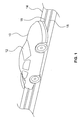
- FIG. 1 is an enlarged, partial, perspective view of one embodiment of the present invention
- FIG. 2 is an enlarged, partial, cross-sectional view of one embodiment of the present invention.
- FIG. 3 is a block depiction of one embodiment of the present invention.
- FIG. 4 is a block depiction of another embodiment of the present invention.
- FIG. 5 is a perspective view of another embodiment of the present invention.
- FIG. 6 is a partial, top plan view of still another embodiment of the present invention.
- FIG. 7 is a partial, top plan view of still another embodiment of the present invention.
- FIG. 8 a shows a frame captured from a first vehicle after a collision with a second vehicle
- FIG. 8 b shows a video augmented view of the scene shown in FIG. 8 a
- FIG. 9 a shows a frame captured by an imaging device in a first vehicle
- FIG. 9 b shows an augmented video frame produced from the frame shown in FIG. 9 a;
- FIG. 10 a is a video frame shot by an onboard camera in a first vehicle.
- FIG. 10 b is the same frame after video augmentation.
- a toy vehicle 10 may progress along a track 14 .
- the vehicle 10 may have an onboard video camera 12 .
- the track 14 may include a pair of conductors 16 and 18 that respectively provide power to and receive video signals from the vehicle 10 and its camera 12 .
- the toy vehicle 10 is referred to herein as a “guided vehicle” because its forward progress is guided. That is, the vehicle 10 is either guided by mechanical features on a track 14 , or is otherwise guided by another characteristic of the track, such as its color, or the signals it emits. Alternatively, the vehicle 10 may be guided by a lead vehicle.
- the lead vehicle may have a target that the video camera 12 can track so that the following vehicle is guided by the lead vehicle, even though no mechanical restraint guides the following vehicle.
- the vehicle 10 includes a video camera 12 coupled to a frame buffer 17 that stores the captured video frames before transmission over an electrical link 20 .
- the electrical link 20 may be a spring contact, in one embodiment of the present invention.
- the link 20 may maintain, through spring force, contact with the track 14 and particularly with the conductor 18 .
- video signals captured by the video camera 12 may be temporarily stored in the frame buffer 17 before transmission to the track 14 .
- the frames may be retransmitted. Alternatively, frames may only be transmitted when good contact is had between the link 20 and the track 14 . Thus, the frame buffer 17 insures that video is not lost if the link 20 leaves the track 14 or bounces with respect to the track 14 .
- a detector 19 included in the frame buffer 17 detects when the link 20 is no longer coupled with the track 14 . This may be accomplished, as one example, by monitoring the spring force of the link 20 . In another embodiment of the present invention, each frame may be sent repeatedly and if both frames are received, the duplicate frame is discarded.
- the progress of the toy vehicle 10 on the track 14 may be controlled by signals provided through the track 14 .
- the speed of the vehicle 10 may be adjusted.
- the vehicle 10 may be controlled by radio frequency signals received through an antenna 34 .
- the power source for the toy vehicle 10 may be the track 14 or an onboard battery, as two examples.
- a mechanical propulsion system such as a friction accelerator, may be utilized to propel the vehicle 10 .
- the video camera 12 is coupled through the frame buffer 17 and the contact 20 to the conductor 18 .
- a separate electrical motor 22 may couple to a separate conductor 16 through the link 20 .
- the video transmitted from the video camera 12 through the frame buffer 17 and the link 20 to the conductor 18 may be received through an interface 26 .
- the received video may be buffered and provided to a controller 28 at a control station 24 .
- the controller 28 may be a microcontroller or other processor-based device.
- the video is then rendered and displayed on a video display device 30 .
- the video display device 30 may be a liquid crystal display, or a computer monitor, as two examples.
- power may be supplied through a power source 27 to the conductor 16 . That power may also be provided to the video camera 12 .
- a single conductor 16 or 18 may also provide power to the vehicle 10 and receive the video from the vehicle 10 .
- an electrical link 20 in the form of an airwave signal may be utilized to transmit the video information.
- the video information is transmitted from an interface 32 and its antenna 34 to the track 14 .
- the track 14 may include a receiving antenna in the form of a wire embedded in the track.
- the transmitter on the toy vehicle 10 need not be very powerful in some embodiments.
- the toy motor 22 may be supplied with power from an onboard source (not shown), such as a battery source, as one example.
- the toy vehicle 10 may include an antenna 34 that interacts with an antenna 16 a and the track 14 a as shown in FIG. 5.
- the antenna 16 a may be embedded in the track 14 a .
- the vehicle 10 then may follow a course along the antenna 16 a , but is not strictly controlled thereby.
- the vehicle 10 may include the camera 12 as described above.
- a variety of structures 36 may be included on the track 14 a , including simulated buildings, people, and other vehicles.
- the structures 36 may be imaged by the video camera 12 to give a realistic effect.
- the track 14 a may be a flat rollout mat.
- a flexible antenna 16 a stitched within the mat, picks up the broadcasted video from the toy vehicle 12 .
- the throttle of the car and the steering of the car may be remotely controlled.
- the user may then create his or her own race track, complete with obstacles and jumps.
- the user may design several city blocks and the toy vehicle 10 may be made to maneuver around those obstacles. Buildings may provide more visual realism interest when seen through the video camera 12 in a relatively small toy vehicle 10 .
- the toy vehicle 10 may follow another toy vehicle 40 .
- the toy vehicle 40 may include a visual target 42 .
- the target 42 may have a particular graphical design or may be of a particular color.
- the video camera 12 in the toy vehicle 10 attempts to follow that target 42 .
- forward progress of the vehicle 10 may be controlled from the controller 28 based on the presence of the target image in the video received from the toy vehicle 10 .
- both the vehicles 40 and 10 may be controlled by airwave signals through antennas 34 and 44 .
- the vehicles 10 and 40 may progress over a track 14 b.
- the user may control the lead vehicle 40 and the trailing vehicle 10 , equipped with the video camera 12 , may follow the lead vehicle 40 .
- Direction control signals may be provided through the antenna 44 to the lead vehicle 40 .
- the vehicle 10 may be equipped with the video camera 12 and may follow a pattern 14 c formed on a mat or other surface 14 b as shown in FIG. 7.
- the pattern 14 c may be a specific color that is recognized by the camera 12 or a coupled processor-based system.
- the camera 12 may then cause the vehicle 10 to continue to progress in a direction of the color pattern 14 c .
- the control of the vehicle 10 may be implemented by the user, physically or automatically, using software operating on the control station 24 .
- the vehicle 10 progresses straightforwardly.
- the vehicle 10 turns in one direction or the other to keep the pattern 14 b in full view.
- a user watching the display 30 may provide the same control.
- the video generated by the vehicle 10 may be utilized to control a characteristic of the vehicle such as its direction or speed of travel.
- the video may also be utilized to change the orientation of the imaging device 12 as still another example.
- the video information may also be analyzed to locate areas of higher or lower ambient luminance, relative motion to the vehicle, such as motion towards or away from the particular vehicle, periodicity such as a blinking light, the vehicle's spatial location with the respect to another object, or texture or pattern. Detection of such characteristics may be used to control the vehicle 10 .
- a pattern such as a barcode or an image object may have a particular aspect ratio which may be analyzed to detect the orientation of that object with respect to the vehicle 10 .
- the video information obtained from the vehicle 10 may be augmented to enhance the user's play, as shown in FIG. 8 b .
- the video taken by the vehicle 10 of the collision may be enhanced at a processor-based control station 24 to show on the display 30 , added visual effects such as smoke or flames 50 as shown in FIG. 8 b .
- Those augmented visual effects may be incorporated over the video of the second vehicle 48 taken by the vehicle 10 .
- the various structures 36 may include an indicia 52 which may recognized by a controller 28 as indicated in FIG. 9 a .
- the controller 28 may then automatically insert more realistic images 54 , as shown in FIG. 9 b , for the relatively simple images of the structures 36 for viewing on the display 30 .
- the video from the vehicle 10 shown in FIG. 10 a, of another vehicle 56 may be enhanced.
- the vehicle 10 appears to have fired a rocket 58 at the vehicle 56 as indicated in FIG. 10 b.
- the vehicle 10 may do nothing, as indicated in FIG. 10 a, but the video obtained from the vehicle 10 may be augmented to include an image 58 of a rocket fired by the vehicle 10 .
- An image may also be generated of the explosive effects, of the type shown in FIG. 8 b , when the rocket image 58 impacts a pattern recognized object such as the vehicle 56 .
- the video enhancement effects may be improved by having an additional video camera, separate and apart from a vehicle 10 , for imaging the play surface.
- the controller 28 may be utilized to enhance the control of the toy vehicle 10 .
- the vehicle 10 may be controlled using a joystick or steering wheel (not shown) coupled to the controller 28 .
- the vehicle 10 may be controlled in a point and click fashion. The user may click on an area of the video display 30 to cause the vehicle 10 to move to that location.
- a route may be provided to the controller 28 and the vehicle 10 may be caused to automatically follow that route under processor-based system control.
- a racetrack (not shown) may be set up for example by real cones. The vehicle 10 may then automatically go around the cones in response to processor-based system control which recognizes the cones and their locations. Games may be implemented wherein various track-based vehicles may be directed towards various track positions in order to “run over” or “consume” virtual images that appear to be positioned by the processor-based system on the image of the tracks when viewed on a display.
Landscapes
- Engineering & Computer Science (AREA)
- Computer Networks & Wireless Communication (AREA)
- Toys (AREA)
Abstract
A guided toy vehicle may be operated with an onboard video camera. The video from the video camera may be transmitted to a control station for display by the user. In some embodiments of the present invention, the video may be transmitted from the vehicle to the control station over the same track that guides the vehicle.
Description
- This invention relates generally to toy vehicles, such as track-based toy cars and toy trains.
- Toy vehicles may be propelled along a track that acts as a guide to cause the vehicles to traverse a desired course. In addition, the vehicles may receive power through contacts in the track. The operator, from a remote location, can control the speed of the vehicles by adjusting the power supplied to each vehicle.
- While this user model has been extremely popular for generations, it has also been relatively unchanged over a large number of years. Thus, it would be desirable to enhance the capabilities of guided toy vehicles.
- FIG. 1 is an enlarged, partial, perspective view of one embodiment of the present invention;
- FIG. 2 is an enlarged, partial, cross-sectional view of one embodiment of the present invention;
- FIG. 3 is a block depiction of one embodiment of the present invention;
- FIG. 4 is a block depiction of another embodiment of the present invention;
- FIG. 5 is a perspective view of another embodiment of the present invention;
- FIG. 6 is a partial, top plan view of still another embodiment of the present invention;
- FIG. 7 is a partial, top plan view of still another embodiment of the present invention;
- FIG. 8 a shows a frame captured from a first vehicle after a collision with a second vehicle;
- FIG. 8 b shows a video augmented view of the scene shown in FIG. 8a;
- FIG. 9 a shows a frame captured by an imaging device in a first vehicle;
- FIG. 9 b shows an augmented video frame produced from the frame shown in FIG. 9a;
- FIG. 10 a is a video frame shot by an onboard camera in a first vehicle; and
- FIG. 10 b is the same frame after video augmentation.
- Referring to FIG. 1, a
toy vehicle 10, illustrated in the form of a toy car, may progress along atrack 14. Thevehicle 10 may have anonboard video camera 12. Thetrack 14 may include a pair ofconductors vehicle 10 and itscamera 12. - The
toy vehicle 10 is referred to herein as a “guided vehicle” because its forward progress is guided. That is, thevehicle 10 is either guided by mechanical features on atrack 14, or is otherwise guided by another characteristic of the track, such as its color, or the signals it emits. Alternatively, thevehicle 10 may be guided by a lead vehicle. For example, the lead vehicle may have a target that thevideo camera 12 can track so that the following vehicle is guided by the lead vehicle, even though no mechanical restraint guides the following vehicle. - Turning next to FIG. 2, the
vehicle 10 includes avideo camera 12 coupled to aframe buffer 17 that stores the captured video frames before transmission over anelectrical link 20. Theelectrical link 20 may be a spring contact, in one embodiment of the present invention. Thelink 20 may maintain, through spring force, contact with thetrack 14 and particularly with theconductor 18. Thus, video signals captured by thevideo camera 12 may be temporarily stored in theframe buffer 17 before transmission to thetrack 14. - If the
track 14 fails to maintain contact with thelink 20, the frames may be retransmitted. Alternatively, frames may only be transmitted when good contact is had between thelink 20 and thetrack 14. Thus, theframe buffer 17 insures that video is not lost if thelink 20 leaves thetrack 14 or bounces with respect to thetrack 14. - In one embodiment of the present invention shown in FIG. 3, a
detector 19 included in theframe buffer 17 detects when thelink 20 is no longer coupled with thetrack 14. This may be accomplished, as one example, by monitoring the spring force of thelink 20. In another embodiment of the present invention, each frame may be sent repeatedly and if both frames are received, the duplicate frame is discarded. - In some embodiments of the present invention, the progress of the
toy vehicle 10 on thetrack 14 may be controlled by signals provided through thetrack 14. Thus, depending on the potentials applied through thetrack 14, the speed of thevehicle 10 may be adjusted. In another embodiment of the present invention, thevehicle 10 may be controlled by radio frequency signals received through anantenna 34. - The power source for the
toy vehicle 10 may be thetrack 14 or an onboard battery, as two examples. In addition, a mechanical propulsion system, such as a friction accelerator, may be utilized to propel thevehicle 10. - Referring to FIG. 3, in one embodiment of the present invention, the
video camera 12 is coupled through theframe buffer 17 and thecontact 20 to theconductor 18. A separateelectrical motor 22 may couple to aseparate conductor 16 through thelink 20. The video transmitted from thevideo camera 12 through theframe buffer 17 and thelink 20 to theconductor 18 may be received through aninterface 26. - The received video may be buffered and provided to a
controller 28 at acontrol station 24. Thecontroller 28 may be a microcontroller or other processor-based device. The video is then rendered and displayed on avideo display device 30. Thevideo display device 30 may be a liquid crystal display, or a computer monitor, as two examples. - In some embodiments of the present invention, power may be supplied through a
power source 27 to theconductor 16. That power may also be provided to thevideo camera 12. Asingle conductor vehicle 10 and receive the video from thevehicle 10. - In accordance with another embodiment of the present invention, instead of providing the video signals over a
physical link 20, anelectrical link 20 in the form of an airwave signal may be utilized to transmit the video information. In one embodiment, shown in FIG. 4, the video information is transmitted from aninterface 32 and itsantenna 34 to thetrack 14. Namely, thetrack 14 may include a receiving antenna in the form of a wire embedded in the track. Thus, the transmitter on thetoy vehicle 10 need not be very powerful in some embodiments. In such case, thetoy motor 22 may be supplied with power from an onboard source (not shown), such as a battery source, as one example. - In accordance with yet another embodiment of the present invention, the
toy vehicle 10 may include anantenna 34 that interacts with anantenna 16 a and thetrack 14 a as shown in FIG. 5. Theantenna 16 a may be embedded in thetrack 14 a. Thevehicle 10 then may follow a course along theantenna 16 a, but is not strictly controlled thereby. Thevehicle 10 may include thecamera 12 as described above. A variety ofstructures 36 may be included on thetrack 14 a, including simulated buildings, people, and other vehicles. Thestructures 36 may be imaged by thevideo camera 12 to give a realistic effect. - In some embodiments of the present invention, the
track 14 a may be a flat rollout mat. Aflexible antenna 16 a, stitched within the mat, picks up the broadcasted video from thetoy vehicle 12. The throttle of the car and the steering of the car may be remotely controlled. The user may then create his or her own race track, complete with obstacles and jumps. Alternatively, the user may design several city blocks and thetoy vehicle 10 may be made to maneuver around those obstacles. Buildings may provide more visual realism interest when seen through thevideo camera 12 in a relativelysmall toy vehicle 10. - Referring next to FIG. 6, the
toy vehicle 10 may follow anothertoy vehicle 40. In one embodiment, thetoy vehicle 40 may include avisual target 42. Thetarget 42 may have a particular graphical design or may be of a particular color. Thevideo camera 12 in thetoy vehicle 10 attempts to follow thattarget 42. In other words, forward progress of thevehicle 10 may be controlled from thecontroller 28 based on the presence of the target image in the video received from thetoy vehicle 10. In one embodiment of the present invention, both thevehicles antennas vehicles track 14 b. - Thus, the user may control the
lead vehicle 40 and the trailingvehicle 10, equipped with thevideo camera 12, may follow thelead vehicle 40. Direction control signals may be provided through theantenna 44 to thelead vehicle 40. - As yet another example, the
vehicle 10 may be equipped with thevideo camera 12 and may follow apattern 14 c formed on a mat orother surface 14 b as shown in FIG. 7. In one embodiment of the present invention, thepattern 14 c may be a specific color that is recognized by thecamera 12 or a coupled processor-based system. Thecamera 12 may then cause thevehicle 10 to continue to progress in a direction of thecolor pattern 14 c. The control of thevehicle 10 may be implemented by the user, physically or automatically, using software operating on thecontrol station 24. - For example, as long as the screen is filled with the particular color represented by the
pattern 14 b, thevehicle 10 progresses straightforwardly. Thevehicle 10 turns in one direction or the other to keep thepattern 14 b in full view. Alternatively, a user watching thedisplay 30 may provide the same control. - In some embodiments of the present invention, the video generated by the
vehicle 10 may be utilized to control a characteristic of the vehicle such as its direction or speed of travel. The video may also be utilized to change the orientation of theimaging device 12 as still another example. The video information may also be analyzed to locate areas of higher or lower ambient luminance, relative motion to the vehicle, such as motion towards or away from the particular vehicle, periodicity such as a blinking light, the vehicle's spatial location with the respect to another object, or texture or pattern. Detection of such characteristics may be used to control thevehicle 10. For example, a pattern such as a barcode or an image object may have a particular aspect ratio which may be analyzed to detect the orientation of that object with respect to thevehicle 10. - In accordance with still another embodiment of the present invention, the video information obtained from the
vehicle 10, as shown in FIG. 8a, may be augmented to enhance the user's play, as shown in FIG. 8b. For example, in the situation where thetoy vehicle 10 collides into anothervehicle 48, the video taken by thevehicle 10 of the collision (FIG. 8a) may be enhanced at a processor-basedcontrol station 24 to show on thedisplay 30, added visual effects such as smoke orflames 50 as shown in FIG. 8b. Those augmented visual effects may be incorporated over the video of thesecond vehicle 48 taken by thevehicle 10. - As another example of video augmentation, for example in connection with the embodiment shown in FIG. 5, the
various structures 36 may include anindicia 52 which may recognized by acontroller 28 as indicated in FIG. 9a. Thecontroller 28 may then automatically insert morerealistic images 54, as shown in FIG. 9b, for the relatively simple images of thestructures 36 for viewing on thedisplay 30. - As still another example, the video from the
vehicle 10, shown in FIG. 10a, of anothervehicle 56 may be enhanced. When the video is viewed on thedisplay 30 thevehicle 10 appears to have fired arocket 58 at thevehicle 56 as indicated in FIG. 10b. In fact, thevehicle 10 may do nothing, as indicated in FIG. 10a, but the video obtained from thevehicle 10 may be augmented to include animage 58 of a rocket fired by thevehicle 10. An image may also be generated of the explosive effects, of the type shown in FIG. 8b, when therocket image 58 impacts a pattern recognized object such as thevehicle 56. In some cases, the video enhancement effects may be improved by having an additional video camera, separate and apart from avehicle 10, for imaging the play surface. - In a number of instances, the
controller 28 may be utilized to enhance the control of thetoy vehicle 10. Thevehicle 10 may be controlled using a joystick or steering wheel (not shown) coupled to thecontroller 28. In addition, thevehicle 10 may be controlled in a point and click fashion. The user may click on an area of thevideo display 30 to cause thevehicle 10 to move to that location. A route may be provided to thecontroller 28 and thevehicle 10 may be caused to automatically follow that route under processor-based system control. A racetrack (not shown) may be set up for example by real cones. Thevehicle 10 may then automatically go around the cones in response to processor-based system control which recognizes the cones and their locations. Games may be implemented wherein various track-based vehicles may be directed towards various track positions in order to “run over” or “consume” virtual images that appear to be positioned by the processor-based system on the image of the tracks when viewed on a display. - While the present invention has been described with respect to a limited number of embodiments, those skilled in the art will appreciate numerous modifications and variations therefrom. It is intended that the appended claims cover all such modifications and variations as fall within the true spirit and scope of this present invention.
Claims (30)
1. A method comprising:
guiding a toy vehicle to move over a surface;
providing an electrical link between the vehicle and the surface;
capturing video from the vehicle; and
transmitting said video from the vehicle to the electrical link.
2. The method of claim 1 wherein guiding the toy vehicle includes enabling the toy vehicle to move along a track.
3. The method of claim 2 wherein enabling the vehicle to move along a track includes guiding the vehicle using the track.
4. The method of claim 3 wherein providing the electrical link includes providing an electrical connection between the vehicle and the track and between the track and the control device and transmitting the video from the vehicle to the track to the control device.
5. The method of claim 2 including providing a pair of conductors in said track including a first conductor to provide power and a second conductor to receive video.
6. The method of claim 1 wherein providing an electrical link includes providing an electrical contact.
7. The method of claim 1 wherein providing the electrical link includes providing an airwave connection.
8. The method of claim 1 wherein guiding the toy vehicle to move over the surface includes providing a airwave link between an antenna in said surface and an antenna on said vehicle.
9. The method of claim 1 wherein guiding the toy vehicle to move over the surface includes guiding a vehicle by causing the vehicle to follow another vehicle.
10. The method of claim 1 wherein guiding the vehicle includes causing the vehicle to follow an indicia on said surface and capturing video of said indicia to guide said vehicle.
11. A toy comprising:
a toy vehicle;
a video imaging device secured to said vehicle; and
an electrical link to convey said video to a vehicle supporting surface.
12. The toy of claim 11 wherein said toy vehicle is a toy car.
13. The toy of claim 11 wherein said toy vehicle is a guided toy vehicle.
14. The toy of claim 13 further including a track to guide said vehicle.
15. The toy of claim 14 wherein said track includes at least one conductor.
16. The toy of claim 15 wherein said conductor provides power to said vehicle.
17. The toy of claim 15 wherein said conductor receives video from said vehicle.
18. The toy of claim 15 including a first conductor to provide power to said vehicle and a second conductor to receive video from said vehicle.
19. The toy of claim 11 wherein said link is an airwave link.
20. The toy of claim 11 further including a video frame buffer coupled between said imaging device and said electrical link.
21. A method comprising:
receiving video from a toy vehicle;
identifying an image element in said video; and
using said image element to control the vehicle.
22. The method of claim 21 including detecting a characteristic of a surface over which said vehicle moves.
23. The method of claim 22 including detecting a color.
24. The method of claim 23 including detecting a pattern on said surface.
25. The method of claim 21 including detecting a visual feature on a second toy vehicle.
26. The method of claim 25 including detecting a target on the second toy vehicle.
27. The method of claim 26 including detecting a color of said target.
28. A toy comprising:
a toy vehicle including a video information generating digital imaging device secured to said toy vehicle; and
a control station communicating with said toy vehicle, said control station augmenting the video information received from said digital imaging device.
29. The toy of claim 28 wherein the direction of travel of said toy vehicle is automatically controlled by said control station.
30. The toy of claim 28 wherein said control station includes a processor-based device that identifies an image element in said video information and causes said toy vehicle to follow said image element.
Priority Applications (1)
| Application Number | Priority Date | Filing Date | Title |
|---|---|---|---|
| US10/404,157 US6692329B2 (en) | 2000-06-20 | 2003-04-01 | Video enhanced guided toy vehicles |
Applications Claiming Priority (2)
| Application Number | Priority Date | Filing Date | Title |
|---|---|---|---|
| US09/596,975 US6568983B1 (en) | 2000-06-20 | 2000-06-20 | Video enhanced guided toy vehicles |
| US10/404,157 US6692329B2 (en) | 2000-06-20 | 2003-04-01 | Video enhanced guided toy vehicles |
Related Parent Applications (1)
| Application Number | Title | Priority Date | Filing Date |
|---|---|---|---|
| US09/596,975 Division US6568983B1 (en) | 2000-06-20 | 2000-06-20 | Video enhanced guided toy vehicles |
Publications (2)
| Publication Number | Publication Date |
|---|---|
| US20030190856A1 true US20030190856A1 (en) | 2003-10-09 |
| US6692329B2 US6692329B2 (en) | 2004-02-17 |
Family
ID=24389515
Family Applications (2)
| Application Number | Title | Priority Date | Filing Date |
|---|---|---|---|
| US09/596,975 Expired - Lifetime US6568983B1 (en) | 2000-06-20 | 2000-06-20 | Video enhanced guided toy vehicles |
| US10/404,157 Expired - Lifetime US6692329B2 (en) | 2000-06-20 | 2003-04-01 | Video enhanced guided toy vehicles |
Family Applications Before (1)
| Application Number | Title | Priority Date | Filing Date |
|---|---|---|---|
| US09/596,975 Expired - Lifetime US6568983B1 (en) | 2000-06-20 | 2000-06-20 | Video enhanced guided toy vehicles |
Country Status (1)
| Country | Link |
|---|---|
| US (2) | US6568983B1 (en) |
Cited By (7)
| Publication number | Priority date | Publication date | Assignee | Title |
|---|---|---|---|---|
| US20070173174A1 (en) * | 2005-11-01 | 2007-07-26 | Mattel, Inc. | Toys with view ports |
| ITLO20080002A1 (en) * | 2008-09-02 | 2008-12-02 | Beta Nit Srl | ELECTROMECHANICAL DEVICE FOR THE TRANSPORT OF VIDEO ACQUISITION SYSTEMS IN APPLICATIONS OF VIRTUAL REALITY AND ARCHITECTURAL ENDOSCOPY, AND METHOD OF PROCESSING AND MODIFICATION OF THE SPEED OF THE FILM ACQUIRED |
| US20090004948A1 (en) * | 2007-06-19 | 2009-01-01 | Konami Digital Entertainment Co., Ltd. | Travelling toy system |
| USD681742S1 (en) | 2011-07-21 | 2013-05-07 | Mattel, Inc. | Toy vehicle |
| USD685862S1 (en) | 2011-07-21 | 2013-07-09 | Mattel, Inc. | Toy vehicle housing |
| US9028291B2 (en) | 2010-08-26 | 2015-05-12 | Mattel, Inc. | Image capturing toy |
| WO2015155557A3 (en) * | 2014-04-10 | 2015-11-26 | Muszka Mihály | Remote controlled simulator system by computer acting experience with devices moving on external site |
Families Citing this family (11)
| Publication number | Priority date | Publication date | Assignee | Title |
|---|---|---|---|---|
| US6568983B1 (en) * | 2000-06-20 | 2003-05-27 | Intel Corporation | Video enhanced guided toy vehicles |
| US7690964B2 (en) * | 2006-05-04 | 2010-04-06 | Mattel, Inc. | Toy ramp devices |
| US7819720B2 (en) * | 2006-05-04 | 2010-10-26 | Mattel, Inc. | Indexing stunt selector for vehicle track set |
| US7402964B1 (en) * | 2006-05-12 | 2008-07-22 | Bradley Calhoun | Race car system |
| EP2049214A4 (en) * | 2006-06-09 | 2012-08-15 | Mattel Inc | Toy track devices |
| JP5083521B2 (en) * | 2007-08-06 | 2012-11-28 | 株式会社セガ | Game device |
| US8662954B2 (en) | 2010-04-30 | 2014-03-04 | Mattel, Inc. | Toy doll for image capture and display |
| US8506343B2 (en) | 2010-04-30 | 2013-08-13 | Mattel, Inc. | Interactive toy doll for image capture and display |
| US8882559B2 (en) * | 2012-08-27 | 2014-11-11 | Bergen E. Fessenmaier | Mixed reality remote control toy and methods therfor |
| US9987557B2 (en) * | 2015-02-23 | 2018-06-05 | Peter Garbowski | Real-time video feed based multiplayer gaming environment |
| US10643406B2 (en) * | 2016-04-20 | 2020-05-05 | Gopro, Inc. | Data logging in aerial platform |
Citations (10)
| Publication number | Priority date | Publication date | Assignee | Title |
|---|---|---|---|---|
| US4636137A (en) * | 1980-10-24 | 1987-01-13 | Lemelson Jerome H | Tool and material manipulation apparatus and method |
| US4986187A (en) * | 1988-12-27 | 1991-01-22 | Lionel Trains, Inc. | Toy vehicle assembly with video display capability |
| US5127658A (en) * | 1989-12-01 | 1992-07-07 | Openiano Renato M | Remotely-controlled light-beam firing and sensing vehicular toy |
| US5481257A (en) * | 1987-03-05 | 1996-01-02 | Curtis M. Brubaker | Remotely controlled vehicle containing a television camera |
| US5596319A (en) * | 1994-10-31 | 1997-01-21 | Spry; Willie L. | Vehicle remote control system |
| US6062942A (en) * | 1997-05-26 | 2000-05-16 | Asahi Corporation | Interactive intersection for toy tracks |
| US6079982A (en) * | 1997-12-31 | 2000-06-27 | Meader; Gregory M | Interactive simulator ride |
| US6497608B2 (en) * | 2001-02-09 | 2002-12-24 | Sampo Technology Corp. | Toy car camera system and rear vision mirrors |
| US6547624B1 (en) * | 1999-01-29 | 2003-04-15 | Interlego Ag | System for recording and editing films |
| US6568983B1 (en) * | 2000-06-20 | 2003-05-27 | Intel Corporation | Video enhanced guided toy vehicles |
Family Cites Families (15)
| Publication number | Priority date | Publication date | Assignee | Title |
|---|---|---|---|---|
| US4214266A (en) * | 1978-06-19 | 1980-07-22 | Myers Charles H | Rear viewing system for vehicles |
| US4277804A (en) * | 1978-11-01 | 1981-07-07 | Elburn Robison | System for viewing the area rearwardly of a vehicle |
| JPS60128699U (en) * | 1984-02-07 | 1985-08-29 | 株式会社トミー | radio controlled toy |
| US4673371A (en) * | 1985-04-26 | 1987-06-16 | Tomy Kogyo Co., Inc. | Robot-like toy vehicle |
| US4709265A (en) * | 1985-10-15 | 1987-11-24 | Advanced Resource Development Corporation | Remote control mobile surveillance system |
| US4697812A (en) * | 1985-12-09 | 1987-10-06 | Elliot Rudell | Off-road slot car and track system |
| US4795154A (en) * | 1987-06-25 | 1989-01-03 | Ideal Loisirs | Continuous slot racing system |
| US5021878A (en) * | 1989-09-20 | 1991-06-04 | Semborg-Recrob, Corp. | Animated character system with real-time control |
| JPH0639755Y2 (en) * | 1989-10-25 | 1994-10-19 | 株式会社トミー | Orbital device for racing games |
| US4993912A (en) * | 1989-12-22 | 1991-02-19 | Chamberlain Mrc, Division Of Duchossois Industries, Inc. | Stair climbing robot |
| US5350033A (en) * | 1993-04-26 | 1994-09-27 | Kraft Brett W | Robotic inspection vehicle |
| JP3049330B2 (en) * | 1993-08-25 | 2000-06-05 | コナミ株式会社 | Game equipment |
| US5669821A (en) * | 1994-04-12 | 1997-09-23 | Prather; James G. | Video augmented amusement rides |
| US20010045978A1 (en) * | 2000-04-12 | 2001-11-29 | Mcconnell Daniel L. | Portable personal wireless interactive video device and method of using the same |
| US6733360B2 (en) * | 2001-02-02 | 2004-05-11 | Interlego Ag | Toy device responsive to visual input |
-
2000
- 2000-06-20 US US09/596,975 patent/US6568983B1/en not_active Expired - Lifetime
-
2003
- 2003-04-01 US US10/404,157 patent/US6692329B2/en not_active Expired - Lifetime
Patent Citations (10)
| Publication number | Priority date | Publication date | Assignee | Title |
|---|---|---|---|---|
| US4636137A (en) * | 1980-10-24 | 1987-01-13 | Lemelson Jerome H | Tool and material manipulation apparatus and method |
| US5481257A (en) * | 1987-03-05 | 1996-01-02 | Curtis M. Brubaker | Remotely controlled vehicle containing a television camera |
| US4986187A (en) * | 1988-12-27 | 1991-01-22 | Lionel Trains, Inc. | Toy vehicle assembly with video display capability |
| US5127658A (en) * | 1989-12-01 | 1992-07-07 | Openiano Renato M | Remotely-controlled light-beam firing and sensing vehicular toy |
| US5596319A (en) * | 1994-10-31 | 1997-01-21 | Spry; Willie L. | Vehicle remote control system |
| US6062942A (en) * | 1997-05-26 | 2000-05-16 | Asahi Corporation | Interactive intersection for toy tracks |
| US6079982A (en) * | 1997-12-31 | 2000-06-27 | Meader; Gregory M | Interactive simulator ride |
| US6547624B1 (en) * | 1999-01-29 | 2003-04-15 | Interlego Ag | System for recording and editing films |
| US6568983B1 (en) * | 2000-06-20 | 2003-05-27 | Intel Corporation | Video enhanced guided toy vehicles |
| US6497608B2 (en) * | 2001-02-09 | 2002-12-24 | Sampo Technology Corp. | Toy car camera system and rear vision mirrors |
Cited By (14)
| Publication number | Priority date | Publication date | Assignee | Title |
|---|---|---|---|---|
| US20070173174A1 (en) * | 2005-11-01 | 2007-07-26 | Mattel, Inc. | Toys with view ports |
| US8376806B2 (en) * | 2005-11-01 | 2013-02-19 | Mattel, Inc. | Toys with view ports |
| US20090004948A1 (en) * | 2007-06-19 | 2009-01-01 | Konami Digital Entertainment Co., Ltd. | Travelling toy system |
| US8257133B2 (en) * | 2007-06-19 | 2012-09-04 | Konami Digital Entertainment Co., Ltd. | Travelling toy system |
| ITLO20080002A1 (en) * | 2008-09-02 | 2008-12-02 | Beta Nit Srl | ELECTROMECHANICAL DEVICE FOR THE TRANSPORT OF VIDEO ACQUISITION SYSTEMS IN APPLICATIONS OF VIRTUAL REALITY AND ARCHITECTURAL ENDOSCOPY, AND METHOD OF PROCESSING AND MODIFICATION OF THE SPEED OF THE FILM ACQUIRED |
| US9028291B2 (en) | 2010-08-26 | 2015-05-12 | Mattel, Inc. | Image capturing toy |
| USD685862S1 (en) | 2011-07-21 | 2013-07-09 | Mattel, Inc. | Toy vehicle housing |
| USD700250S1 (en) | 2011-07-21 | 2014-02-25 | Mattel, Inc. | Toy vehicle |
| USD701578S1 (en) | 2011-07-21 | 2014-03-25 | Mattel, Inc. | Toy vehicle |
| USD703275S1 (en) | 2011-07-21 | 2014-04-22 | Mattel, Inc. | Toy vehicle housing |
| USD703766S1 (en) | 2011-07-21 | 2014-04-29 | Mattel, Inc. | Toy vehicle housing |
| USD709139S1 (en) | 2011-07-21 | 2014-07-15 | Mattel, Inc. | Wheel |
| USD681742S1 (en) | 2011-07-21 | 2013-05-07 | Mattel, Inc. | Toy vehicle |
| WO2015155557A3 (en) * | 2014-04-10 | 2015-11-26 | Muszka Mihály | Remote controlled simulator system by computer acting experience with devices moving on external site |
Also Published As
| Publication number | Publication date |
|---|---|
| US6692329B2 (en) | 2004-02-17 |
| US6568983B1 (en) | 2003-05-27 |
Similar Documents
| Publication | Publication Date | Title |
|---|---|---|
| US6568983B1 (en) | Video enhanced guided toy vehicles | |
| US5707237A (en) | Driving simulation system | |
| US10953330B2 (en) | Reality vs virtual reality racing | |
| US6707487B1 (en) | Method for representing real-time motion | |
| DE69207134T2 (en) | Lock train with moving vehicles for several participants | |
| US6567116B1 (en) | Multiple object tracking system | |
| US20040224740A1 (en) | Simulation system | |
| KR20100137413A (en) | Mobile body competition implementation system | |
| KR20190063883A (en) | System for providing augmented reality interactive game contents using a drones | |
| JP4117579B2 (en) | Amusement facility, amusement facility vehicle and amusement facility display device | |
| US20030112264A1 (en) | Real time authoring | |
| GB2365360A (en) | A simulation game with realtime input from real competitors | |
| CN116088722A (en) | Virtual interactive system | |
| GB2365790A (en) | Competitive simulation with real time input from real event | |
| JP3082156U (en) | Simulated riding control radio control model | |
| JPH0719511Y2 (en) | Game device | |
| JPH10277261A (en) | Image synthesis device and virtual experience device using the same | |
| GB2518602A (en) | Systems and methods for virtual participation in a real, live event | |
| JP2017099790A (en) | Traveling object operation system | |
| JPH07110301B2 (en) | Circuit game equipment | |
| WO2021215483A1 (en) | Video processing system using unmanned moving body, video processing method, and video processing device | |
| JPH0530799Y2 (en) | ||
| TWI473049B (en) | Emulation play system for emulating real vision and motion | |
| CN113674520A (en) | Novel racing car competition system | |
| CN108594783B (en) | Air-water pipe system and air-water experience system |
Legal Events
| Date | Code | Title | Description |
|---|---|---|---|
| STCF | Information on status: patent grant |
Free format text: PATENTED CASE |
|
| FEPP | Fee payment procedure |
Free format text: PAYOR NUMBER ASSIGNED (ORIGINAL EVENT CODE: ASPN); ENTITY STATUS OF PATENT OWNER: LARGE ENTITY |
|
| FPAY | Fee payment |
Year of fee payment: 4 |
|
| FPAY | Fee payment |
Year of fee payment: 8 |
|
| FPAY | Fee payment |
Year of fee payment: 12 |