US20030190518A1 - Fuel cell - Google Patents
Fuel cell Download PDFInfo
- Publication number
- US20030190518A1 US20030190518A1 US10/118,389 US11838902A US2003190518A1 US 20030190518 A1 US20030190518 A1 US 20030190518A1 US 11838902 A US11838902 A US 11838902A US 2003190518 A1 US2003190518 A1 US 2003190518A1
- Authority
- US
- United States
- Prior art keywords
- fuel cell
- electrolytic
- layer
- gas diffusion
- layers
- Prior art date
- Legal status (The legal status is an assumption and is not a legal conclusion. Google has not performed a legal analysis and makes no representation as to the accuracy of the status listed.)
- Granted
Links
- 239000000446 fuel Substances 0.000 title claims abstract description 146
- 239000007789 gas Substances 0.000 claims description 131
- 239000000463 material Substances 0.000 claims description 95
- 239000003054 catalyst Substances 0.000 claims description 85
- 238000009792 diffusion process Methods 0.000 claims description 67
- 239000003792 electrolyte Substances 0.000 claims description 62
- 239000012528 membrane Substances 0.000 claims description 26
- 229920000642 polymer Polymers 0.000 claims description 26
- BASFCYQUMIYNBI-UHFFFAOYSA-N platinum Chemical compound [Pt] BASFCYQUMIYNBI-UHFFFAOYSA-N 0.000 claims description 22
- -1 polytetrafluoroethylene Polymers 0.000 claims description 17
- 239000004810 polytetrafluoroethylene Substances 0.000 claims description 17
- 229920001343 polytetrafluoroethylene Polymers 0.000 claims description 17
- QVGXLLKOCUKJST-UHFFFAOYSA-N atomic oxygen Chemical compound [O] QVGXLLKOCUKJST-UHFFFAOYSA-N 0.000 claims description 13
- 238000000034 method Methods 0.000 claims description 13
- 239000001301 oxygen Substances 0.000 claims description 13
- 229910052760 oxygen Inorganic materials 0.000 claims description 13
- 229910052697 platinum Inorganic materials 0.000 claims description 9
- 230000007423 decrease Effects 0.000 claims description 7
- YCKRFDGAMUMZLT-UHFFFAOYSA-N Fluorine atom Chemical compound [F] YCKRFDGAMUMZLT-UHFFFAOYSA-N 0.000 claims description 5
- 229920001577 copolymer Polymers 0.000 claims description 5
- 239000011737 fluorine Substances 0.000 claims description 5
- 229910052731 fluorine Inorganic materials 0.000 claims description 5
- HCDGVLDPFQMKDK-UHFFFAOYSA-N hexafluoropropylene Chemical group FC(F)=C(F)C(F)(F)F HCDGVLDPFQMKDK-UHFFFAOYSA-N 0.000 claims description 5
- 239000000203 mixture Substances 0.000 claims description 5
- 239000011236 particulate material Substances 0.000 claims description 5
- BFKJFAAPBSQJPD-UHFFFAOYSA-N tetrafluoroethene Chemical group FC(F)=C(F)F BFKJFAAPBSQJPD-UHFFFAOYSA-N 0.000 claims description 5
- 239000011347 resin Substances 0.000 claims description 4
- 229920005989 resin Polymers 0.000 claims description 4
- 229920002313 fluoropolymer Polymers 0.000 claims description 3
- 229920000554 ionomer Polymers 0.000 claims description 3
- NBVXSUQYWXRMNV-UHFFFAOYSA-N fluoromethane Chemical class FC NBVXSUQYWXRMNV-UHFFFAOYSA-N 0.000 claims description 2
- 239000002826 coolant Substances 0.000 description 35
- XLYOFNOQVPJJNP-UHFFFAOYSA-N water Substances O XLYOFNOQVPJJNP-UHFFFAOYSA-N 0.000 description 19
- 238000006243 chemical reaction Methods 0.000 description 18
- 239000011230 binding agent Substances 0.000 description 10
- 150000002978 peroxides Chemical class 0.000 description 10
- 230000036647 reaction Effects 0.000 description 10
- 229920000557 Nafion® Polymers 0.000 description 7
- 238000004891 communication Methods 0.000 description 7
- 238000006731 degradation reaction Methods 0.000 description 7
- 239000012530 fluid Substances 0.000 description 7
- 230000015556 catabolic process Effects 0.000 description 6
- 239000007784 solid electrolyte Substances 0.000 description 6
- 239000007806 chemical reaction intermediate Substances 0.000 description 5
- 238000010586 diagram Methods 0.000 description 5
- 239000000047 product Substances 0.000 description 5
- 239000000126 substance Substances 0.000 description 5
- 239000000725 suspension Substances 0.000 description 5
- UFHFLCQGNIYNRP-UHFFFAOYSA-N Hydrogen Chemical compound [H][H] UFHFLCQGNIYNRP-UHFFFAOYSA-N 0.000 description 4
- 230000002411 adverse Effects 0.000 description 4
- 230000000694 effects Effects 0.000 description 4
- 239000001257 hydrogen Substances 0.000 description 4
- 229910052739 hydrogen Inorganic materials 0.000 description 4
- 239000007787 solid Substances 0.000 description 4
- OKTJSMMVPCPJKN-UHFFFAOYSA-N Carbon Chemical compound [C] OKTJSMMVPCPJKN-UHFFFAOYSA-N 0.000 description 3
- 230000004888 barrier function Effects 0.000 description 3
- 229910052799 carbon Inorganic materials 0.000 description 3
- 239000006229 carbon black Substances 0.000 description 3
- 230000003647 oxidation Effects 0.000 description 3
- 238000007254 oxidation reaction Methods 0.000 description 3
- 239000002245 particle Substances 0.000 description 3
- XEEYBQQBJWHFJM-UHFFFAOYSA-N Iron Chemical compound [Fe] XEEYBQQBJWHFJM-UHFFFAOYSA-N 0.000 description 2
- KDLHZDBZIXYQEI-UHFFFAOYSA-N Palladium Chemical compound [Pd] KDLHZDBZIXYQEI-UHFFFAOYSA-N 0.000 description 2
- 229910001260 Pt alloy Inorganic materials 0.000 description 2
- 229910002848 Pt–Ru Inorganic materials 0.000 description 2
- 230000003197 catalytic effect Effects 0.000 description 2
- 230000003247 decreasing effect Effects 0.000 description 2
- 239000000543 intermediate Substances 0.000 description 2
- 239000011872 intimate mixture Substances 0.000 description 2
- 150000002500 ions Chemical class 0.000 description 2
- 239000007788 liquid Substances 0.000 description 2
- 239000012466 permeate Substances 0.000 description 2
- 239000000376 reactant Substances 0.000 description 2
- MYMOFIZGZYHOMD-UHFFFAOYSA-N Dioxygen Chemical compound O=O MYMOFIZGZYHOMD-UHFFFAOYSA-N 0.000 description 1
- KRHYYFGTRYWZRS-UHFFFAOYSA-N Fluorane Chemical compound F KRHYYFGTRYWZRS-UHFFFAOYSA-N 0.000 description 1
- ZOKXTWBITQBERF-UHFFFAOYSA-N Molybdenum Chemical compound [Mo] ZOKXTWBITQBERF-UHFFFAOYSA-N 0.000 description 1
- KJTLSVCANCCWHF-UHFFFAOYSA-N Ruthenium Chemical compound [Ru] KJTLSVCANCCWHF-UHFFFAOYSA-N 0.000 description 1
- 238000010521 absorption reaction Methods 0.000 description 1
- 229910045601 alloy Inorganic materials 0.000 description 1
- 239000000956 alloy Substances 0.000 description 1
- 230000000712 assembly Effects 0.000 description 1
- 238000000429 assembly Methods 0.000 description 1
- 239000003575 carbonaceous material Substances 0.000 description 1
- 239000013065 commercial product Substances 0.000 description 1
- 150000001875 compounds Chemical class 0.000 description 1
- 238000009833 condensation Methods 0.000 description 1
- 230000005494 condensation Effects 0.000 description 1
- 230000000593 degrading effect Effects 0.000 description 1
- 239000008367 deionised water Substances 0.000 description 1
- 238000013461 design Methods 0.000 description 1
- 229910001882 dioxygen Inorganic materials 0.000 description 1
- 239000006185 dispersion Substances 0.000 description 1
- 238000001035 drying Methods 0.000 description 1
- 239000004744 fabric Substances 0.000 description 1
- 125000004435 hydrogen atom Chemical group [H]* 0.000 description 1
- 229910000040 hydrogen fluoride Inorganic materials 0.000 description 1
- 230000002209 hydrophobic effect Effects 0.000 description 1
- 239000012535 impurity Substances 0.000 description 1
- 239000003014 ion exchange membrane Substances 0.000 description 1
- 229910052741 iridium Inorganic materials 0.000 description 1
- GKOZUEZYRPOHIO-UHFFFAOYSA-N iridium atom Chemical compound [Ir] GKOZUEZYRPOHIO-UHFFFAOYSA-N 0.000 description 1
- 229910052742 iron Inorganic materials 0.000 description 1
- 229910052750 molybdenum Inorganic materials 0.000 description 1
- 239000011733 molybdenum Substances 0.000 description 1
- 229910000484 niobium oxide Inorganic materials 0.000 description 1
- URLJKFSTXLNXLG-UHFFFAOYSA-N niobium(5+);oxygen(2-) Chemical compound [O-2].[O-2].[O-2].[O-2].[O-2].[Nb+5].[Nb+5] URLJKFSTXLNXLG-UHFFFAOYSA-N 0.000 description 1
- 229910000510 noble metal Inorganic materials 0.000 description 1
- QGLKJKCYBOYXKC-UHFFFAOYSA-N nonaoxidotritungsten Chemical compound O=[W]1(=O)O[W](=O)(=O)O[W](=O)(=O)O1 QGLKJKCYBOYXKC-UHFFFAOYSA-N 0.000 description 1
- 238000013021 overheating Methods 0.000 description 1
- 230000001590 oxidative effect Effects 0.000 description 1
- BPUBBGLMJRNUCC-UHFFFAOYSA-N oxygen(2-);tantalum(5+) Chemical compound [O-2].[O-2].[O-2].[O-2].[O-2].[Ta+5].[Ta+5] BPUBBGLMJRNUCC-UHFFFAOYSA-N 0.000 description 1
- RVTZCBVAJQQJTK-UHFFFAOYSA-N oxygen(2-);zirconium(4+) Chemical compound [O-2].[O-2].[Zr+4] RVTZCBVAJQQJTK-UHFFFAOYSA-N 0.000 description 1
- 229910052763 palladium Inorganic materials 0.000 description 1
- CFQCIHVMOFOCGH-UHFFFAOYSA-N platinum ruthenium Chemical compound [Ru].[Pt] CFQCIHVMOFOCGH-UHFFFAOYSA-N 0.000 description 1
- 238000002360 preparation method Methods 0.000 description 1
- 230000001737 promoting effect Effects 0.000 description 1
- 229910052703 rhodium Inorganic materials 0.000 description 1
- 239000010948 rhodium Substances 0.000 description 1
- MHOVAHRLVXNVSD-UHFFFAOYSA-N rhodium atom Chemical compound [Rh] MHOVAHRLVXNVSD-UHFFFAOYSA-N 0.000 description 1
- 229910052707 ruthenium Inorganic materials 0.000 description 1
- 229920006395 saturated elastomer Polymers 0.000 description 1
- 238000005245 sintering Methods 0.000 description 1
- 239000002002 slurry Substances 0.000 description 1
- 238000010561 standard procedure Methods 0.000 description 1
- 125000000542 sulfonic acid group Chemical group 0.000 description 1
- 229910001936 tantalum oxide Inorganic materials 0.000 description 1
- 238000012546 transfer Methods 0.000 description 1
- 229910001930 tungsten oxide Inorganic materials 0.000 description 1
- 229910001928 zirconium oxide Inorganic materials 0.000 description 1
Images


Classifications
-
- H—ELECTRICITY
- H01—ELECTRIC ELEMENTS
- H01M—PROCESSES OR MEANS, e.g. BATTERIES, FOR THE DIRECT CONVERSION OF CHEMICAL ENERGY INTO ELECTRICAL ENERGY
- H01M4/00—Electrodes
- H01M4/86—Inert electrodes with catalytic activity, e.g. for fuel cells
- H01M4/90—Selection of catalytic material
- H01M4/92—Metals of platinum group
- H01M4/925—Metals of platinum group supported on carriers, e.g. powder carriers
- H01M4/926—Metals of platinum group supported on carriers, e.g. powder carriers on carbon or graphite
-
- H—ELECTRICITY
- H01—ELECTRIC ELEMENTS
- H01M—PROCESSES OR MEANS, e.g. BATTERIES, FOR THE DIRECT CONVERSION OF CHEMICAL ENERGY INTO ELECTRICAL ENERGY
- H01M4/00—Electrodes
- H01M4/86—Inert electrodes with catalytic activity, e.g. for fuel cells
- H01M4/8605—Porous electrodes
-
- H—ELECTRICITY
- H01—ELECTRIC ELEMENTS
- H01M—PROCESSES OR MEANS, e.g. BATTERIES, FOR THE DIRECT CONVERSION OF CHEMICAL ENERGY INTO ELECTRICAL ENERGY
- H01M4/00—Electrodes
- H01M4/86—Inert electrodes with catalytic activity, e.g. for fuel cells
- H01M4/88—Processes of manufacture
-
- H—ELECTRICITY
- H01—ELECTRIC ELEMENTS
- H01M—PROCESSES OR MEANS, e.g. BATTERIES, FOR THE DIRECT CONVERSION OF CHEMICAL ENERGY INTO ELECTRICAL ENERGY
- H01M4/00—Electrodes
- H01M4/86—Inert electrodes with catalytic activity, e.g. for fuel cells
- H01M4/90—Selection of catalytic material
- H01M4/92—Metals of platinum group
-
- H—ELECTRICITY
- H01—ELECTRIC ELEMENTS
- H01M—PROCESSES OR MEANS, e.g. BATTERIES, FOR THE DIRECT CONVERSION OF CHEMICAL ENERGY INTO ELECTRICAL ENERGY
- H01M4/00—Electrodes
- H01M4/86—Inert electrodes with catalytic activity, e.g. for fuel cells
- H01M2004/8678—Inert electrodes with catalytic activity, e.g. for fuel cells characterised by the polarity
- H01M2004/8689—Positive electrodes
-
- Y—GENERAL TAGGING OF NEW TECHNOLOGICAL DEVELOPMENTS; GENERAL TAGGING OF CROSS-SECTIONAL TECHNOLOGIES SPANNING OVER SEVERAL SECTIONS OF THE IPC; TECHNICAL SUBJECTS COVERED BY FORMER USPC CROSS-REFERENCE ART COLLECTIONS [XRACs] AND DIGESTS
- Y02—TECHNOLOGIES OR APPLICATIONS FOR MITIGATION OR ADAPTATION AGAINST CLIMATE CHANGE
- Y02E—REDUCTION OF GREENHOUSE GAS [GHG] EMISSIONS, RELATED TO ENERGY GENERATION, TRANSMISSION OR DISTRIBUTION
- Y02E60/00—Enabling technologies; Technologies with a potential or indirect contribution to GHG emissions mitigation
- Y02E60/30—Hydrogen technology
- Y02E60/50—Fuel cells
Definitions
- the invention relates to fuel cells.
- a fuel cell can convert chemical energy to electrical energy by promoting a chemical reaction between two gases.
- one of the gases enters the anode flow field plate at the inlet region of the anode flow field plate and flows through the channels of the anode flow field plate toward the outlet region of the anode flow field plate.
- the other gas enters the cathode flow field plate at the inlet region of the cathode flow field plate and flows through the channels of the cathode flow field plate toward the cathode flow field plate outlet region.
- the anode gas flows through the channels of the anode flow field plate, the anode gas passes through the anode gas diffusion layer and interacts with the anode catalyst.
- the cathode gas passes through the cathode gas diffusion layer and interacts with the cathode catalyst.
- the anode catalyst interacts with the anode gas to catalyze the conversion of the anode gas to reaction intermediates.
- the reaction intermediates include ions and electrons.
- the cathode catalyst interacts with the cathode gas and the reaction intermediates to catalyze the conversion of the cathode gas to the chemical product of the fuel cell reaction.
- the chemical product of the fuel cell reaction flows through a gas diffusion layer to the channels of a flow field plate (e.g., the cathode flow field plate).
- the chemical product then flows along the channels of the flow field plate toward the outlet region of the flow field plate.
- the electrolyte provides a barrier to the flow of the electrons and gases from one side of the membrane electrode assembly to the other side of the membrane electrode assembly. However, the electrolyte allows ionic reaction intermediates to flow from the anode side of the membrane electrode assembly to the cathode side of the membrane electrode assembly.
- the ionic reaction intermediates can flow from the anode side of the membrane electrode assembly to the cathode side of the membrane electrode assembly without exiting the fuel cell.
- the electrons flow from the anode side of the membrane electrode assembly to the cathode side of the membrane electrode assembly by electrically connecting an external load between the anode flow field plate and the cathode flow field plate.
- the external load allows the electrons to flow from the anode side of the membrane electrode assembly, through the anode flow field plate, through the load and to the cathode flow field plate.
- Electrons are formed at the anode side of the membrane electrode assembly, indicating that the anode gas undergoes oxidation during the fuel cell reaction. Electrons are consumed at the cathode side of the membrane electrode assembly, indicating that the cathode gas undergoes reduction during the fuel cell reaction.
- Equation 1 the hydrogen forms protons (H + ) and electrons.
- the protons flow through the electrolyte to the cathode side of the membrane electrode assembly, and the electrons flow from the anode side of the membrane electrode assembly to the cathode side of the membrane electrode assembly through the external load.
- the electrons and protons react with the oxygen to form water.
- Equation 3 shows the overall fuel cell reaction.
- a plurality of fuel cells can be arranged in series to form a fuel cell stack.
- a fuel cell stack one side of a flow field plate functions as the anode flow field plate for one fuel cell while the opposite side of the flow field plate functions as the cathode flow field plate in another fuel cell.
- This arrangement may be referred to as a bipolar plate.
- the stack may also include monopolar plates such as, for example, an anode coolant flow field plate having one side that serves as an anode flow field plate and another side that serves as a coolant flow field plate.
- the open-faced coolant channels of an anode coolant flow field plate and a cathode coolant flow field plate may be mated to form collective coolant channels to cool the adjacent flow field plates forming fuel cells.
- the invention relates to fuel cells.
- the peroxide in embodiments in which the electrolyte includes a fluorocarbon polymer, can be catalyzed by impurities, e.g., iron, in the electrolyte, and hydrogen fluoride (a product of a degradation reaction) can be detected in a gas stream exiting the fuel cell stack.
- impurities e.g., iron
- hydrogen fluoride a product of a degradation reaction
- the degree of degradation is further enhanced. In some cases, for about every 10° C. increase in operating temperature, the degree of electrolyte degradation can double.
- the fuel cell can further include a second non-electrolytic layer between the second catalyst layer and the second gas diffusion layer.
- the invention features a fuel cell including a first gas diffusion layer, a second gas diffusion layer, an electrolyte between the first and the second gas diffusion layers, a first catalyst layer between the electrolyte and the first gas diffusion layer, the first catalyst layer comprising a first electrolytic polymer and a first non-electrolytic polymer, and a second catalyst layer between the electrolyte and the second gas diffusion layer.
- the second catalyst layer can include a second electrolytic polymer and a second non-electrolytic polymer.
- the invention features a method of operating a fuel cell system.
- the method includes contacting a first gas with a first non-electrolytic layer contained in a first fuel cell, and contacting the first gas with a first catalyst layer contained in the first fuel cell.
- Embodiments may include one or more of the following features.
- the first gas can include a cathode gas, e.g., having oxygen.
- the first gas can contact the first non-electrolytic layer before the first gas contacts the first catalyst layer.
- the method further includes contacting a second gas with a second non-electrolytic layer contained in the first fuel cell, and contacting the second gas with a second catalyst layer contained in the first fuel cell.
- the first non-electrolytic layer includes polytetrafluoroethylene and platinum.
- the invention features a fuel cell including an electrolyte, a gas diffusion layer, a plurality of layers between the electrolyte and the gas diffusion layer, at least two of the layers having different concentrations of a non-electrolytic material, and an electrode layer between the electrolyte and the plurality of layers.
- the invention features a fuel cell having an electrolyte, a gas diffusion layer, and a plurality of layers between the electrolyte and the gas diffusion layer.
- At least two of the plurality of layers include a non-electrolytic material and an electrolytic material, and at least two of the plurality of layers having different concentrations of the non-electrolytic material.
- the plurality of layers can include a catalyst.
- the non-electrolytic material can include polytetrafluoroethylene.
- FIG. 2 is a partial schematic diagram of an embodiment of a fuel cell .
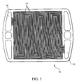
- FIG. 3 shows an embodiment of a cathode flow field plate .
- FIG. 8 is a partial schematic diagram of an embodiment of a fuel cell.
- FIG. 1 shows a fuel cell system 20 including a fuel cell stack 22 that has a plurality of fuel cells 24 .
- Fuel cell system 20 also includes an anode gas supply 26 , an anode gas inlet line 28 , an anode gas outlet line 30 , a cathode gas inlet line 32 , a cathode gas outlet line 34 , a coolant inlet line 36 , and a coolant outlet line 38 .
- FIG. 2 shows an embodiment of fuel cell 24 having a membrane electrode assembly (MEA) 40 , a non-electrolytic layer 42 , gas diffusion layers (GDLs) 44 and 46 , a cathode flow field plate 48 , and an anode flow field plate 50 .
- MEA 40 includes a cathode 52 , an anode 54 , and a solid electrolyte 56 between electrodes 52 and 54 .
- Cathode flow field plate 48 has cathode gas channels 250
- anode flow field plate 50 has anode gas channels 280 .
- Fuel cells 24 can be arranged by having the back surface of a cathode flow field plate of one fuel cell serve as the anode flow field plate in an adjacent fuel cell. A plurality of coolant flow field plates (described below) can also be used in this arrangement.
- Non-electrolytic layer 42 is generally configured to reduce, e.g., minimize, the adverse effect of peroxide that can form during operation of fuel cell system 20 and/or to reduce the adverse effect of water that can condense in fuel cells 24 .
- non-electrolytic layer 42 can electrolytically isolate carbon material in GDL 44 , e.g., from oxygen, to reduce peroxide generation.
- non-electrolytic layer 42 includes a mixture of a catalyst and a non-electrolytic material as a binder.
- the catalyst in non-electrolytic layer 42 is typically formed of a particulate material capable of being used in a fuel cell during operating conditions, and capable of reducing a concentration of peroxide.
- the catalyst can catalyze the reaction of peroxide formed during the cathode reaction, e.g., at the cathode/non-electrolytic layer interface, into water and oxygen, thereby reducing degradation of the electrolyte.
- the catalyst is also capable of interacting with protons, electrons, and oxygen to form water.
- Examples of catalysts include platinum, e.g., platinum black, ruthenium, iridium, rhodium, palladium, molybdenum, and their alloys. Other suitable catalysts having the above characteristics can be used.
- the catalyst is unsupported on another material, i.e., a support material.
- a support material such as carbon
- the unsupported catalyst particles can have relatively large surface area, such as between about 60 m 2 /g and 120 m 2 /g, e.g., greater than 60, 70, 80, 90, 100, or 110 m 2 /g, and/or less than 120, 110, 100, 90, 80, or 70 m 2 /g.
- the catalyst particles be relatively small, such as less than about 45 angstroms, e.g., ⁇ 40, ⁇ 35, ⁇ 30, ⁇ 25, ⁇ 20, ⁇ 15, or ⁇ 10 angstroms.
- the catalyst can be supported on another material, such a material resistant to oxidation and/or reduction. Distributing the catalyst on a support material allows the catalytic activity of non-electrolytic layer 42 to be maintained at the same level as using bulk, unsupported catalyst, while the total amount of catalyst in the non-electrolytic layer can be reduced, thereby reducing the cost of forming the non-electrolytic layer. That is, while less catalyst may be used to form non-electrolytic layer 42 , a greater fraction of the catalyst is effectively used for the fuel cell reaction, as compared to using bulk, unsupported catalyst.
- support materials include tungsten oxide, zirconium oxide, niobium oxide, tantalum oxide, and carbon.
- the catalyst can be loaded on a support material between about 0.5 mg/cm 2 to about 2.0 mg/cm 2 , e.g., greater than 0.5, 0.75, 1.0, 1.25, 1.5, or 1.75 mg/cm 2 , and/or less than 2.0, 1.75, 1.5, 1.25, 1.0, or 0.75 mg/cm 2 , of the support material.
- the catalyst unsupported or supported on another material, is formed into a mechanically-bonded mixture with the non-electrolytic material as a binder.
- the binder can minimize the adverse effect of condensed water on fuel cell system 20 .
- the binder can be a non-ionomeric material.
- the binder can be a material that has relatively low water absorbency. In certain embodiments, the binder has water absorbency lower than that of an ionomer commercially available as NAFION (duPont).
- the binder is a hydrophobic material that repels and/or disperses condensed water.
- non-electrolytic materials include fluorine-containing compounds such as polytetrafluoroethylene (PTFE), and copolymers of tetrafluoroethylene and hexafluoropropylene.
- the binder can prevent protons from conducting through non-electrolytic layer 42 .
- protons formed at anode 54 that migrate through electrolyte 56 and cathode 52 are generally isolated from GDL 44 .
- GDL 44 can be protected from degradation, such as from oxidizing or reducing conditions in fuel cell 24 .
- Non-electrolytic layer 42 generally includes an amount of binder that is sufficient to hold the layer together physically but which does not adversely decrease the electrical conductivity of the non-electrolytic layer.
- non-electrolytic layer 42 can be sufficiently electrically conductive such that electrons produced at anode 54 can flow through GDL 44 and the non-electrolytic layer, and to cathode 52 , where the electrons can react with protons and oxygen according to the cathode reaction.
- non-electrolytic layer 42 can include less than about 30%, e.g., greater 0, 5, 10, 15, 20, or 25%, and/or less than 30, 25, 20, 15, 10, or 5%, of the non-electrolytic binder, with the remainder of the layer being the catalyst.
- non-electrolytic layer 42 can vary.
- non-electrolytic layer 42 can be as thick as cathode 52 or anode 54 , or thicker than either electrode.
- Non-electrolytic layer 42 can be formed by applying a suspension (e.g., platinum black and PTFE) to a decal, and drying the decal at an elevated temperature. After the decal has dried, it is hot pressed on to catalyst layer 52 to transfer the non-electrolytic layer to the catalyst layer. Alternatively, a suspension is applied to the surface of a gas diffusion layer (described below) that faces solid electrolyte 56 , and the suspension is then dried. The method of preparing non-electrolytic layer 42 may further include the use of pressure and temperature to achieve bonding.
- a suspension e.g., platinum black and PTFE
- Electrolyte 56 should be capable of allowing ions to flow therethrough while providing a substantial resistance to the flow of electrons.
- electrolyte 56 is a solid polymer (e.g., a solid polymer ion exchange membrane), such as a solid polymer proton exchange membrane (e.g., a solid polymer containing sulfonic acid groups).
- a solid polymer proton exchange membrane e.g., a solid polymer containing sulfonic acid groups.
- Such membranes are commercially available from E. I. DuPont de Nemours Company (Wilmington, Del.) under the trademark NAFION.
- electrolyte 56 can also be prepared from the commercial product GORE-SELECT, available from W. L. Gore & Associates (Elkton, Md.).
- Cathode 52 can be formed of a material capable of interacting with oxygen, electrons and protons to form water. Examples of such materials include, for example, platinum, platinum alloys, and noble metals dispersed on carbon black. Cathode 52 can further include an electrolyte, such as an ionomeric material, e.g., NAFION, that allows the cathode to conduct protons. Cathode 52 can be prepared as described above with respect to anode 54 .
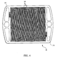
- FIG. 4 shows an anode flow field plate 50 having an inlet 260 , an outlet 270 , and open-faced channels 280 that define a flow path for an anode gas from inlet 260 to outlet 270 .
- An anode gas flows from the anode gas inlet line 28 and enters flow field plate 50 via inlet 260 .
- the anode gas then flows along channels 280 and exits flow field plate 50 via outlet 270 to anode outlet line 30 .
- hydrogen contained in the anode gas can permeate gas diffusion layer 46 and interact with anode 54 to form protons and electrons.
- the protons pass through solid electrolyte 56 , and the electrons are conducted through gas diffusion layer 46 to anode flow field plate 50 , ultimately flowing through an external load to cathode flow field plate 48 .
- fuel cell 24 further includes a second non-electrolytic layer 100 between anode 54 and GDL 46 (FIG. 6).
- Non-electrolytic layer 100 can be generally the same as non-electrolytic layer 42 .
- fuel cell 24 includes a non-electrolytic layer between anode 54 and GDL 46 only, i.e., the fuel cell does not include a non-electrolytic layer between cathode 52 and GDL 44 .
- a fuel cell 200 similar to fuel cell 24 , includes multiple (here, six) non-electrolytic layers 42 A, 42 B, 42 C, 42 D, 42 E, and 42 F.
- Layers 42 A, 42 B, 42 C, 42 D, 42 E, and 42 F are generally formed as described above for layer 42 , but layers 42 A, 42 B, 42 C, 42 D, 42 E, and 42 F have different concentrations of non-electrolytic material and/or catalyst, relative to each other.
- the non-electrolytic layer having the lowest concentration of non-electrolytic material and/or catalyst may have a zero concentration of non-electrolytic material and/or catalyst.
- layer 42 A may have up to 30% of the non-electrolytic material
- layer 42 F may have 0% of the non-electrolytic material.
- layers 42 A, 42 B, 42 C, 42 D, 42 E, and 42 F have concentrations of non-electrolytic material and/or catalyst that increase, from lowest near GDL 44 to highest near electrolyte 56 .
- multiple non-electrolytic layers 42 can also be used between anode 54 and GDL 46 to provide a concentration gradient of non-electrolytic material and/or the catalyst, as described above.
- the multiple non-electrolytic layers can have similar or different dimensions, e.g., thickness.
- non-electrolytic layer 42 is described as a layer discrete from cathode 52 or anode 54
- components of the non-electrolytic layer and the electrodes 52 or 54 can be combined into one layer.
- a fuel cell can include an electrode layer (e.g., between electrolyte 56 and GDL 44 ) having an intimate mixture of one or more catalysts (e.g., Pt-Ru and/or Pt black), an electrolytic material (e.g., NAFION), and a non-electrolytic material (e.g., PTFE).
- This electrode layer can be used on either side or both sides of the solid electrolyte.
- the electrode configuration e.g., thickness or composition, can be optimized to enhance fuel cell performance.
- the catalyst(s), electrolytic material, and non-electrolytic material can be generally the same as described above.
- a fuel cell may include multiple layers that include components of non-electrolytic layer 42 combined with components of electrodes 52 or 54 . That is, non-electrolytic layer 42 and electrodes 52 or 54 are not discrete layers.
- a fuel cell 210 includes multiple (here, four) layers 212 A, 212 B, 212 C, and 212 D between GDL 44 and electrolyte 56 .
- layer 212 D can have the highest concentration of electrolytic material (e.g., NAFION), and layer 212 A can have the lowest concentration, e.g., zero concentration, of the electrolytic material.
- layer 212 D can have the lowest concentration (e.g., zero concentration) of non-electrolytic material (e.g. PTFE), and layer 212 A can have the highest concentration of the non-electrolytic material.
- the concentration gradients for the electrolytic material and the non-electrolytic material can be both linear, both non-linear, or a combination of linear or non-linear, e.g., the concentration gradient for the electrolytic material can be linear and the concentration gradient for the non-electrolytic material can be non-linear.
- the concentration gradient can be substantially linear, e.g. constant, or non-linear, e.g., lock step, or having concentration gradients and plateaus.
- Fuel cell 210 can include, for example, more than 5, 10, 15, 20, 25, 30, 35, 40, 45, or 50 of layers 212 , such as layers 212 A, 212 B, 212 C, and 212 D. Alternatively or in addition, multiple layers 212 , such as layers 212 A, 212 B, 212 C, and 212 D, can be used on the anode side of fuel cell 210 .
- Fuel cell 210 can have a concentration gradient with respect to the electrolytic material, the non-electrolytic material, and/or the catalyst.
Landscapes
- Chemical & Material Sciences (AREA)
- Chemical Kinetics & Catalysis (AREA)
- Electrochemistry (AREA)
- General Chemical & Material Sciences (AREA)
- Engineering & Computer Science (AREA)
- Materials Engineering (AREA)
- Manufacturing & Machinery (AREA)
- Inert Electrodes (AREA)
- Fuel Cell (AREA)
Abstract
Description
- The invention relates to fuel cells.
- A fuel cell can convert chemical energy to electrical energy by promoting a chemical reaction between two gases.
- One type of fuel cell includes a cathode flow field plate, an anode flow field plate, a membrane electrode assembly disposed between the cathode flow field plate and the anode flow field plate, and two gas diffusion layers disposed between the cathode flow field plate and the anode flow field plate. A fuel cell can also include one or more coolant flow field plates disposed adjacent the exterior of the anode flow field plate and/or the exterior of the cathode flow field plate.
- Each flow field plate has an inlet region, an outlet region and open-faced channels connecting the inlet region to the outlet region and providing a way for distributing the gases to the membrane electrode assembly.
- The membrane electrode assembly usually includes a solid electrolyte (e.g., a proton exchange membrane, commonly abbreviated as a PEM) between a first catalyst and a second catalyst. One gas diffusion layer is between the first catalyst and the anode flow field plate, and the other gas diffusion layer is between the second catalyst and the cathode flow field plate.
- During operation of the fuel cell, one of the gases (the anode gas) enters the anode flow field plate at the inlet region of the anode flow field plate and flows through the channels of the anode flow field plate toward the outlet region of the anode flow field plate. The other gas (the cathode gas) enters the cathode flow field plate at the inlet region of the cathode flow field plate and flows through the channels of the cathode flow field plate toward the cathode flow field plate outlet region.
- As the anode gas flows through the channels of the anode flow field plate, the anode gas passes through the anode gas diffusion layer and interacts with the anode catalyst. Similarly, as the cathode gas flows through the channels of the cathode flow field plate, the cathode gas passes through the cathode gas diffusion layer and interacts with the cathode catalyst.
- The anode catalyst interacts with the anode gas to catalyze the conversion of the anode gas to reaction intermediates. The reaction intermediates include ions and electrons. The cathode catalyst interacts with the cathode gas and the reaction intermediates to catalyze the conversion of the cathode gas to the chemical product of the fuel cell reaction.
- The chemical product of the fuel cell reaction flows through a gas diffusion layer to the channels of a flow field plate (e.g., the cathode flow field plate). The chemical product then flows along the channels of the flow field plate toward the outlet region of the flow field plate.
- The electrolyte provides a barrier to the flow of the electrons and gases from one side of the membrane electrode assembly to the other side of the membrane electrode assembly. However, the electrolyte allows ionic reaction intermediates to flow from the anode side of the membrane electrode assembly to the cathode side of the membrane electrode assembly.
- Therefore, the ionic reaction intermediates can flow from the anode side of the membrane electrode assembly to the cathode side of the membrane electrode assembly without exiting the fuel cell. In contrast, the electrons flow from the anode side of the membrane electrode assembly to the cathode side of the membrane electrode assembly by electrically connecting an external load between the anode flow field plate and the cathode flow field plate. The external load allows the electrons to flow from the anode side of the membrane electrode assembly, through the anode flow field plate, through the load and to the cathode flow field plate.
- Electrons are formed at the anode side of the membrane electrode assembly, indicating that the anode gas undergoes oxidation during the fuel cell reaction. Electrons are consumed at the cathode side of the membrane electrode assembly, indicating that the cathode gas undergoes reduction during the fuel cell reaction.
- For example, when hydrogen and oxygen are the gases used in a fuel cell, the hydrogen flows through the anode flow field plate and undergoes oxidation. The oxygen flows through the cathode flow field plate and undergoes reduction. The specific reactions that occur in the fuel cell are represented in equations 1-3.
- H2→2H++2e − (1)
- ½O2+2H++2e −→H2O (2)
- H2+½O2→H2O (3)
- As shown in equation 1, the hydrogen forms protons (H +) and electrons. The protons flow through the electrolyte to the cathode side of the membrane electrode assembly, and the electrons flow from the anode side of the membrane electrode assembly to the cathode side of the membrane electrode assembly through the external load. As shown in equation 2, the electrons and protons react with the oxygen to form water. Equation 3 shows the overall fuel cell reaction.
- In addition to forming chemical products, the fuel cell reaction produces heat. One or more coolant flow field plates are typically used to conduct the heat away from the fuel cell and prevent it from overheating.
- Each coolant flow field plate has an inlet region, an outlet region and channels that provide fluid communication between the coolant flow field plate inlet region and the coolant flow field plate outlet region. A coolant (e.g., liquid de-ionized water) at a relatively low temperature enters the coolant flow field plate at the inlet region, flows through the channels of the coolant flow field plate toward the outlet region of the coolant flow field plate, and exits the coolant flow field plate at the outlet region of the coolant flow field plate. As the coolant flows through the channels of the coolant flow field plate, the coolant absorbs heat formed in the fuel cell. When the coolant exits the coolant flow field plate, the heat absorbed by the coolant is removed from the fuel cell.
- To increase the electrical energy available, a plurality of fuel cells can be arranged in series to form a fuel cell stack. In a fuel cell stack, one side of a flow field plate functions as the anode flow field plate for one fuel cell while the opposite side of the flow field plate functions as the cathode flow field plate in another fuel cell. This arrangement may be referred to as a bipolar plate. The stack may also include monopolar plates such as, for example, an anode coolant flow field plate having one side that serves as an anode flow field plate and another side that serves as a coolant flow field plate. As an example, the open-faced coolant channels of an anode coolant flow field plate and a cathode coolant flow field plate may be mated to form collective coolant channels to cool the adjacent flow field plates forming fuel cells.
- The invention relates to fuel cells.
- Under some operating conditions, such as those occurring at high operating levels and/or at relatively high temperatures, the performance of a fuel cell or a fuel cell stack can be reduced, for example, compared to when the fuel cell or fuel cell stack is operating at relatively lower temperatures and/or operating levels. Without wishing to be bound by theory, it is believed that this decreased performance can be caused by degradation of the electrolyte by peroxide. It is believed that peroxide can be produced from the chemical reaction occurring at the cathode, e.g., as an intermediate; and/or peroxide can be produced as a result of protons and oxygen diffusing through the electrolyte. The peroxide is capable of reacting with and degrading the electrolyte. For example, in embodiments in which the electrolyte includes a fluorocarbon polymer, the peroxide can be catalyzed by impurities, e.g., iron, in the electrolyte, and hydrogen fluoride (a product of a degradation reaction) can be detected in a gas stream exiting the fuel cell stack. At relatively high temperatures, the degree of degradation is further enhanced. In some cases, for about every 10° C. increase in operating temperature, the degree of electrolyte degradation can double.
- Decreased performance of the fuel cell or the fuel cell stack can also be caused by condensation of water carried by a reactant gas, which can be saturated with water. Condensed water can act a gas diffusion barrier, e.g., by resisting the flow of oxygen gas. As a result, this can lower the performance of the fuel cell by preventing the fuel cell reactions from occurring.
- In one aspect, the invention features a fuel cell or a fuel cell stack having good resistance to membrane degradation and/or good handling of condensed water, e.g., good dispersion or low absorption of water. In some embodiments, the fuel cell or the fuel cell stack minimizes peroxide. In certain embodiments, the fuel cell or the fuel cell stack allows condensed water to be effectively removed from the cell or stack. As a result, the performance of the fuel cell or the fuel cell stack can be enhanced, e.g., at high operating levels. In embodiments, the fuel cell or the fuel cell stack includes one or more non-electrolytic layers adjacent to one or more catalyst layers. The non-electrolytic layer can have a relatively compact and economical design.
- In another aspect, the invention features a fuel cell including a first gas diffusion layer, a second gas diffusion layer, an electrolyte between the first and the second gas diffusion layers, a first catalyst layer between the electrolyte and the first gas diffusion layer, a first non-electrolytic layer between the first catalyst layer and the first gas diffusion layer, and a second catalyst layer between the electrolyte and the second gas diffusion layer.
- Embodiments may include one or more of the following features. The first nonelectrolytic layer includes a non-electrolytic polymer, such as a fluorine-containing resin, e.g., polytetrafluoroethylene. The first non-electrolytic layer includes a copolymer of tetrafluoroethylene and hexafluoropropylene. The first non-electrolytic layer includes electrically conductive particulate material, such as platinum, e.g., unsupported on another material. The first catalyst layer is a cathode or an anode. The electrolyte includes a proton exchange membrane. The first non-electrolytic layer is discrete from the first catalyst layer.
- The fuel cell can further include a second non-electrolytic layer between the second catalyst layer and the second gas diffusion layer.
- The fuel cell can further include a first flow plate, and a second flow plate, wherein the first gas diffusion layer is between the first non-electrolytic layer and the first flow plate, and the second gas diffusion layer is between the second catalyst layer and the second flow plate.
- The first non-electrolytic layer can have a thickness substantially equal to the thickness of the first catalyst layer.
- In another aspect, the invention features a fuel cell including a first gas diffusion layer, a second gas diffusion layer, an electrolyte between the first and the second gas diffusion layers, a first catalyst layer between the electrolyte and the first gas diffusion layer, the first catalyst layer comprising a first electrolytic polymer and a first non-electrolytic polymer, and a second catalyst layer between the electrolyte and the second gas diffusion layer.
- Embodiments may include one or more of the following features. The first electrolytic polymer includes an ionomer, such as a sulphonated fluorocarbon polymer. The first non-electrolytic polymer includes a fluorine-containing resin, such as polytetrafluoroethylene. The first non-electrolytic polymer includes a copolymer of tetrafluoroethylene and hexafluoropropylene. The first electrolytic polymer and the first non-electrolytic polymer form a mixture.
- The second catalyst layer can include a second electrolytic polymer and a second non-electrolytic polymer.
- In another aspect, the invention features a method of operating a fuel cell system. The method includes contacting a first gas with a first non-electrolytic layer contained in a first fuel cell, and contacting the first gas with a first catalyst layer contained in the first fuel cell.
- Embodiments may include one or more of the following features. The first gas can include a cathode gas, e.g., having oxygen. The first gas can contact the first non-electrolytic layer before the first gas contacts the first catalyst layer. The method further includes contacting a second gas with a second non-electrolytic layer contained in the first fuel cell, and contacting the second gas with a second catalyst layer contained in the first fuel cell. The first non-electrolytic layer includes polytetrafluoroethylene and platinum.
- In another aspect, the invention features a fuel cell including an electrolyte, a gas diffusion layer, a plurality of layers between the electrolyte and the gas diffusion layer, at least two of the layers having different concentrations of a non-electrolytic material, and an electrode layer between the electrolyte and the plurality of layers.
- Embodiments may include one or more of the following features. The plurality of layers includes a layer adjacent to the gas diffusion layer having the highest concentration of non-electrolytic material relative to other layers of the plurality of layers. The plurality of layers includes a concentration gradient of the non-electrolytic material between the electrolyte and the gas diffusion layer. The concentration gradient is substantially linear. The concentration gradient decreases from the gas diffusion layer to the electrolyte. The non-electrolytic material includes polytetrafluoroethylene.
- In another aspect, the invention features a fuel cell having an electrolyte, a gas diffusion layer, and a plurality of layers between the electrolyte and the gas diffusion layer.
- At least two of the plurality of layers include a non-electrolytic material and an electrolytic material, and at least two of the plurality of layers having different concentrations of the non-electrolytic material.
- Embodiments may include one or more of the following features. The plurality of layers includes a layer adjacent to the gas diffusion layer having the highest concentration of the non-electrolytic material relative to the other layers of the plurality of layers. The plurality of layers includes a concentration gradient of the non-electrolytic material between the electrolyte and the gas diffusion layer. The concentration gradient of the non-electrolytic material is substantially linear. The concentration gradient of the non-electrolytic material decreases from the gas diffusion layer to the electrolyte. The plurality of layers includes a layer adjacent to the electrolyte having the highest concentration of electrolytic material relative to other layers of the plurality of layers. The plurality of layers includes a concentration gradient of the electrolytic material between the electrolyte and the gas diffusion layer. The concentration gradient of the electrolytic material is substantially linear. The concentration gradient of the electrolytic material increases from the gas diffusion layer to the electrolyte.
- The plurality of layers can include a catalyst. The non-electrolytic material can include polytetrafluoroethylene.
- Other features, aspects, and advantages of the invention will be apparent from the drawings, description, and claims.
- FIG. 1 is a partial schematic diagram of an embodiment of a fuel cell system.
- FIG. 2 is a partial schematic diagram of an embodiment of a fuel cell .
- FIG. 3 shows an embodiment of a cathode flow field plate .
- FIG. 4 shows an embodiment of an anode flow field plate.
- FIG. 5 shows an embodiment of a coolant flow field plate.
- FIG. 6 is a partial schematic diagram of an embodiment of a fuel cell.
- FIG. 7 is a partial schematic diagram of an embodiment of a fuel cell.
- FIG. 8 is a partial schematic diagram of an embodiment of a fuel cell.
- FIG. 1 shows a fuel cell system 20 including a
fuel cell stack 22 that has a plurality offuel cells 24. Fuel cell system 20 also includes ananode gas supply 26, an anodegas inlet line 28, an anodegas outlet line 30, a cathodegas inlet line 32, a cathodegas outlet line 34, acoolant inlet line 36, and acoolant outlet line 38. - FIG. 2 shows an embodiment of
fuel cell 24 having a membrane electrode assembly (MEA) 40, anon-electrolytic layer 42, gas diffusion layers (GDLs) 44 and 46, a cathodeflow field plate 48, and an anodeflow field plate 50.MEA 40 includes acathode 52, ananode 54, and asolid electrolyte 56 betweenelectrodes flow field plate 48 hascathode gas channels 250, and anode flowfield plate 50 hasanode gas channels 280.Fuel cells 24 can be arranged by having the back surface of a cathode flow field plate of one fuel cell serve as the anode flow field plate in an adjacent fuel cell. A plurality of coolant flow field plates (described below) can also be used in this arrangement. -
Non-electrolytic layer 42 is generally configured to reduce, e.g., minimize, the adverse effect of peroxide that can form during operation of fuel cell system 20 and/or to reduce the adverse effect of water that can condense infuel cells 24. For example,non-electrolytic layer 42 can electrolytically isolate carbon material inGDL 44, e.g., from oxygen, to reduce peroxide generation. In some embodiments,non-electrolytic layer 42 includes a mixture of a catalyst and a non-electrolytic material as a binder. - The catalyst in
non-electrolytic layer 42 is typically formed of a particulate material capable of being used in a fuel cell during operating conditions, and capable of reducing a concentration of peroxide. For example, the catalyst can catalyze the reaction of peroxide formed during the cathode reaction, e.g., at the cathode/non-electrolytic layer interface, into water and oxygen, thereby reducing degradation of the electrolyte. In some embodiments, the catalyst is also capable of interacting with protons, electrons, and oxygen to form water. Examples of catalysts include platinum, e.g., platinum black, ruthenium, iridium, rhodium, palladium, molybdenum, and their alloys. Other suitable catalysts having the above characteristics can be used. - In some embodiments, the catalyst is unsupported on another material, i.e., a support material. Under some operating conditions, a support material, such as carbon, can be modified, e.g., oxidized at low current densities, which can cause the catalyst particles to agglomerate. As a result, the effectiveness of the catalyst, e.g., catalyst utilization, can be reduced. For enhanced catalytic activity, the unsupported catalyst particles can have relatively large surface area, such as between about 60 m 2/g and 120 m2/g, e.g., greater than 60, 70, 80, 90, 100, or 110 m2/g, and/or less than 120, 110, 100, 90, 80, or 70 m2/g. The catalyst particles be relatively small, such as less than about 45 angstroms, e.g., <40, <35, <30, <25, <20, <15, or <10 angstroms.
- Alternatively or in addition, the catalyst can be supported on another material, such a material resistant to oxidation and/or reduction. Distributing the catalyst on a support material allows the catalytic activity of
non-electrolytic layer 42 to be maintained at the same level as using bulk, unsupported catalyst, while the total amount of catalyst in the non-electrolytic layer can be reduced, thereby reducing the cost of forming the non-electrolytic layer. That is, while less catalyst may be used to formnon-electrolytic layer 42, a greater fraction of the catalyst is effectively used for the fuel cell reaction, as compared to using bulk, unsupported catalyst. Examples of support materials include tungsten oxide, zirconium oxide, niobium oxide, tantalum oxide, and carbon. The catalyst can be loaded on a support material between about 0.5 mg/cm2 to about 2.0 mg/cm 2, e.g., greater than 0.5, 0.75, 1.0, 1.25, 1.5, or 1.75 mg/cm2, and/or less than 2.0, 1.75, 1.5, 1.25, 1.0, or 0.75 mg/cm2, of the support material. - The catalyst, unsupported or supported on another material, is formed into a mechanically-bonded mixture with the non-electrolytic material as a binder. The binder can minimize the adverse effect of condensed water on fuel cell system 20. The binder can be a non-ionomeric material. The binder can be a material that has relatively low water absorbency. In certain embodiments, the binder has water absorbency lower than that of an ionomer commercially available as NAFION (duPont). In some embodiments, the binder is a hydrophobic material that repels and/or disperses condensed water. As a result, condensed water can be easily removed from the fuel cell or fuel cell stack by fuel cell gases, thereby minimizing the effect of water as a barrier against the reactant gases and maximizing the fuel cell reactions. Examples of non-electrolytic materials include fluorine-containing compounds such as polytetrafluoroethylene (PTFE), and copolymers of tetrafluoroethylene and hexafluoropropylene.
- Furthermore, since it is non-electrolytic, the binder can prevent protons from conducting through
non-electrolytic layer 42. Thus, protons formed atanode 54 that migrate throughelectrolyte 56 andcathode 52 are generally isolated fromGDL 44. As a result,GDL 44 can be protected from degradation, such as from oxidizing or reducing conditions infuel cell 24. -
Non-electrolytic layer 42 generally includes an amount of binder that is sufficient to hold the layer together physically but which does not adversely decrease the electrical conductivity of the non-electrolytic layer. For example,non-electrolytic layer 42 can be sufficiently electrically conductive such that electrons produced atanode 54 can flow throughGDL 44 and the non-electrolytic layer, and tocathode 52, where the electrons can react with protons and oxygen according to the cathode reaction. For example,non-electrolytic layer 42 can include less than about 30%, e.g., greater 0, 5, 10, 15, 20, or 25%, and/or less than 30, 25, 20, 15, 10, or 5%, of the non-electrolytic binder, with the remainder of the layer being the catalyst. - The thickness of
non-electrolytic layer 42 can vary. For example,non-electrolytic layer 42 can be as thick ascathode 52 oranode 54, or thicker than either electrode. -
Non-electrolytic layer 42 can be formed by applying a suspension (e.g., platinum black and PTFE) to a decal, and drying the decal at an elevated temperature. After the decal has dried, it is hot pressed on tocatalyst layer 52 to transfer the non-electrolytic layer to the catalyst layer. Alternatively, a suspension is applied to the surface of a gas diffusion layer (described below) that facessolid electrolyte 56, and the suspension is then dried. The method of preparingnon-electrolytic layer 42 may further include the use of pressure and temperature to achieve bonding. -
Electrolyte 56 should be capable of allowing ions to flow therethrough while providing a substantial resistance to the flow of electrons. In some embodiments,electrolyte 56 is a solid polymer (e.g., a solid polymer ion exchange membrane), such as a solid polymer proton exchange membrane (e.g., a solid polymer containing sulfonic acid groups). Such membranes are commercially available from E. I. DuPont de Nemours Company (Wilmington, Del.) under the trademark NAFION. Alternatively,electrolyte 56 can also be prepared from the commercial product GORE-SELECT, available from W. L. Gore & Associates (Elkton, Md.). -
Anode 54 can be formed of a material capable of interacting with hydrogen to form protons and electrons. Examples of such materials include, for example, platinum, platinum alloys, such as platinum-ruthenium, and platinum dispersed on carbon black.Anode 54 can further include an electrolyte, such as an ionomeric material, e.g., NAFION, that allows the anode to conduct protons. Alternatively, a suspension is applied to the surfaces of gas diffusion layers (described below) that facesolid electrolyte 56, and the suspension is then dried. During the preparation ofMEA 40, catalyst material (e.g., platinum) can be applied toelectrolyte 56 using standard techniques. The method of preparinganode 54 may further include the use of pressure and temperature to achieve bonding. -
Cathode 52 can be formed of a material capable of interacting with oxygen, electrons and protons to form water. Examples of such materials include, for example, platinum, platinum alloys, and noble metals dispersed on carbon black.Cathode 52 can further include an electrolyte, such as an ionomeric material, e.g., NAFION, that allows the cathode to conduct protons.Cathode 52 can be prepared as described above with respect toanode 54. - Gas diffusion layers 44 and 46 are electrically conductive so that electrons can flow from
anode 54 to flowfield plate 50 and fromflow field plate 48 tocathode 52. GDLs can be formed of a material that is both gas and liquid permeable. It may also be desirable to provide the GDLs with a planarizing layer, for example, by infusing a porous carbon cloth or paper with a slurry of carbon black followed by sintering with a polytetrafluoroethylene material. Suitable GDLs are available from various companies such as Etek in Natick, Mass., and Zoltek in St. Louis, Mo. - FIG. 3 shows a cathode
flow field plate 48 having aninlet 230, anoutlet 240, and open-faced channels 250 that define a flow path for a cathode gas frominlet 230 tooutlet 240. A cathode gas flows from cathodegas inlet line 32 and enters flowfield plate 48 viainlet 230 tocathode outlet line 54. The cathode gas then flows alongchannels 250 and exits flowfield plate 48 viaoutlet 240. As the cathode gas flows alongchannels 250, oxygen contained in the cathode gas can permeate gas diffusion layer 44 (and layer 42) and interact withcathode 52. Electrons and protons present atcathode 52 react with the oxygen to form water. The water can pass back throughdiffusion layer 44, enter the cathode gas stream inchannels 250, andexit plate 48 through cathode flowfield plate outlet 240. - FIG. 4 shows an anode
flow field plate 50 having aninlet 260, anoutlet 270, and open-faced channels 280 that define a flow path for an anode gas frominlet 260 tooutlet 270. An anode gas flows from the anodegas inlet line 28 and enters flowfield plate 50 viainlet 260. The anode gas then flows alongchannels 280 and exits flowfield plate 50 viaoutlet 270 toanode outlet line 30. As the anode gas flows alongchannels 280, hydrogen contained in the anode gas can permeategas diffusion layer 46 and interact withanode 54 to form protons and electrons. The protons pass throughsolid electrolyte 56, and the electrons are conducted throughgas diffusion layer 46 to anode flowfield plate 50, ultimately flowing through an external load to cathodeflow field plate 48. - Heat produced during the fuel cell reaction is removed from
fuel cell 24 by flowing a coolant through the fuel cell via a coolant flow field plate. FIG. 5 shows a coolantflow field plate 300 having aninlet 310, anoutlet 320 and open-faced channels 330 that define a flow path for coolant frominlet 310 tooutlet 320. The coolant entersfuel cell 24 fromcoolant inlet line 36 viainlet 310, flows alongchannels 330 and absorbs heat, and exitsfuel cell 24 viaoutlet 320 tocoolant outlet line 38. -
Fuel cells 24 are arranged withinfuel cell stack 22 such thatinlets 260 are configured to be in fluid communication with anodegas inlet line 28,andoutlets 270 are configured to be in fluid communication with anodegas outlet line 30. Similarly,inlets 230 are configured to be in fluid communication with cathodegas inlet line 32, andoutlets 240 are configured to be in fluid communication with cathodegas outlet line 34. Likewise,inlets 310 are configured to be in fluid communication withcoolant inlet line 36, andoutlets 320 are configured to be in fluid communication with cathodegas outlet line 38. - Methods of making membrane electrode assemblies and membrane electrode units are described, for example, in U.S. Pat. No. 5,211,984, which is hereby incorporated by reference.
- In some embodiments,
fuel cell 24 further includes a second non-electrolytic layer 100 betweenanode 54 and GDL 46 (FIG. 6). Non-electrolytic layer 100 can be generally the same asnon-electrolytic layer 42. In some embodiments,fuel cell 24 includes a non-electrolytic layer betweenanode 54 andGDL 46 only, i.e., the fuel cell does not include a non-electrolytic layer betweencathode 52 andGDL 44. - In other embodiments, multiple
non-electrolytic layers 42 can be used, e.g., to provide an assembly or stack having a concentration gradient of the non-electrolytic material and/or the catalyst. Referring to FIG. 7, afuel cell 200, similar tofuel cell 24, includes multiple (here, six)non-electrolytic layers Layers layer 42, but layers 42A, 42B, 42C, 42D, 42E, and 42F have different concentrations of non-electrolytic material and/or catalyst, relative to each other. In some embodiments, layers 42A, 42B, 42C, 42D, 42E, and 42F have concentrations of non-electrolytic material and/or catalyst that decrease, from highest nearGDL 44 to lowest nearcathode 52. For example,layer 42A (which is adjacent to GDL 44) has the highest concentration of non-electrolytic material and/or catalyst (relative tolayers 42B-42F),layer 42F (which is adjacent to cathode 52) has the lowest concentration of non-electrolytic material and/or catalyst (relative tolayers 42A-42E), and layers 42B, 42C, 42D, and 42E have intermediate concentrations of non-electrolytic material and/or catalyst to form a concentration gradient of non-electrolytic material and/or catalyst acrosslayers layer 42A may have up to 30% of the non-electrolytic material, andlayer 42F may have 0% of the non-electrolytic material. - The concentration gradient can be substantially linear or non-linear, e.g., lock step, or having concentration gradients and plateaus. For example, for a fuel cell having a linear concentration gradient across a plurality of substantially similar non-electrolytic layers, (e.g., six layers, 42A-42G), the layers can have a concentration of non-electrolytic material such as 30%, 25%, 20%, 15%, 10%, 5%, and 0%, from the electrolyte to the GDL, or from the GDL to the electrolyte.
Fuel cell 200 can include, for example, more than 5, 10, 15, 20, 25, 30, 35, 40, 45, or 50 non-electrolytic layers. Increasing the number non-electrolytic layers can enhance the uniformity and/or linearity of the concentration gradient. - In other embodiments, layers 42A, 42B, 42C, 42D, 42E, and 42F have concentrations of non-electrolytic material and/or catalyst that increase, from lowest near
GDL 44 to highest nearelectrolyte 56. Alternatively or in addition, multiplenon-electrolytic layers 42 can also be used betweenanode 54 andGDL 46 to provide a concentration gradient of non-electrolytic material and/or the catalyst, as described above. The multiple non-electrolytic layers can have similar or different dimensions, e.g., thickness. - While in some of the above embodiments
non-electrolytic layer 42 is described as a layer discrete fromcathode 52 oranode 54, in other embodiments, components of the non-electrolytic layer and theelectrodes electrolyte 56 and GDL 44) having an intimate mixture of one or more catalysts (e.g., Pt-Ru and/or Pt black), an electrolytic material (e.g., NAFION), and a non-electrolytic material (e.g., PTFE). This electrode layer can be used on either side or both sides of the solid electrolyte. The electrode configuration, e.g., thickness or composition, can be optimized to enhance fuel cell performance. The catalyst(s), electrolytic material, and non-electrolytic material can be generally the same as described above. - In certain embodiments, a fuel cell may include multiple layers that include components of
non-electrolytic layer 42 combined with components ofelectrodes non-electrolytic layer 42 andelectrodes fuel cell 210 includes multiple (here, four)layers GDL 44 andelectrolyte 56.Layers Layers GDL 44 to lowest nearelectrolyte 56, as similarly described above forlayers 42A-42F. In other embodiments, layers 212A, 212B, 212C, and 212D have concentrations of non-electrolytic material, electrolytic material, and/or catalyst that increase, from lowest nearGDL 44 to highest nearelectrolyte 56, as described above. - For example,
layer 212D can have the highest concentration of electrolytic material (e.g., NAFION), andlayer 212A can have the lowest concentration, e.g., zero concentration, of the electrolytic material. Alternatively or in addition,layer 212D can have the lowest concentration (e.g., zero concentration) of non-electrolytic material (e.g. PTFE), andlayer 212A can have the highest concentration of the non-electrolytic material. The concentration gradients for the electrolytic material and the non-electrolytic material can be both linear, both non-linear, or a combination of linear or non-linear, e.g., the concentration gradient for the electrolytic material can be linear and the concentration gradient for the non-electrolytic material can be non-linear. - The concentration gradient can be substantially linear, e.g. constant, or non-linear, e.g., lock step, or having concentration gradients and plateaus.
Fuel cell 210 can include, for example, more than 5, 10, 15, 20, 25, 30, 35, 40, 45, or 50 of layers 212, such aslayers layers fuel cell 210.Fuel cell 210 can have a concentration gradient with respect to the electrolytic material, the non-electrolytic material, and/or the catalyst. - Other embodiments are in the claims.
Claims (46)
Priority Applications (6)
| Application Number | Priority Date | Filing Date | Title |
|---|---|---|---|
| US10/118,389 US6756150B2 (en) | 2002-04-08 | 2002-04-08 | Fuel cell having a non-electrolytic layer |
| US10/279,632 US20030190517A1 (en) | 2002-04-08 | 2002-10-24 | Fuel cell |
| PCT/US2003/010627 WO2003088388A1 (en) | 2002-04-08 | 2003-04-07 | Fuel cell |
| AU2003223500A AU2003223500A1 (en) | 2002-04-08 | 2003-04-07 | Fuel cell |
| EP03719630A EP1495503A4 (en) | 2002-04-08 | 2003-04-07 | Fuel cell |
| US10/846,973 US20040214073A1 (en) | 2002-04-08 | 2004-05-14 | Fuel cell having a non-electrolytic layer |
Applications Claiming Priority (1)
| Application Number | Priority Date | Filing Date | Title |
|---|---|---|---|
| US10/118,389 US6756150B2 (en) | 2002-04-08 | 2002-04-08 | Fuel cell having a non-electrolytic layer |
Related Child Applications (2)
| Application Number | Title | Priority Date | Filing Date |
|---|---|---|---|
| US10/279,632 Continuation-In-Part US20030190517A1 (en) | 2002-04-08 | 2002-10-24 | Fuel cell |
| US10/846,973 Division US20040214073A1 (en) | 2002-04-08 | 2004-05-14 | Fuel cell having a non-electrolytic layer |
Publications (2)
| Publication Number | Publication Date |
|---|---|
| US20030190518A1 true US20030190518A1 (en) | 2003-10-09 |
| US6756150B2 US6756150B2 (en) | 2004-06-29 |
Family
ID=28674417
Family Applications (2)
| Application Number | Title | Priority Date | Filing Date |
|---|---|---|---|
| US10/118,389 Expired - Lifetime US6756150B2 (en) | 2002-04-08 | 2002-04-08 | Fuel cell having a non-electrolytic layer |
| US10/846,973 Abandoned US20040214073A1 (en) | 2002-04-08 | 2004-05-14 | Fuel cell having a non-electrolytic layer |
Family Applications After (1)
| Application Number | Title | Priority Date | Filing Date |
|---|---|---|---|
| US10/846,973 Abandoned US20040214073A1 (en) | 2002-04-08 | 2004-05-14 | Fuel cell having a non-electrolytic layer |
Country Status (1)
| Country | Link |
|---|---|
| US (2) | US6756150B2 (en) |
Cited By (7)
| Publication number | Priority date | Publication date | Assignee | Title |
|---|---|---|---|---|
| US20060099486A1 (en) * | 2004-11-05 | 2006-05-11 | Bhaskar Sompalli | Split architectures for MEA durability |
| US20110065026A1 (en) * | 2009-09-17 | 2011-03-17 | Ford Motor Company | Fuel cell with catalyst layer supported on flow field plate |
| US20130252132A1 (en) * | 2012-03-26 | 2013-09-26 | Kabushiki Kaisha Toshiba | Noble metal catalyst layer, membrane electrode assembly, and method for producing noble metal catalyst layer |
| US20130280636A1 (en) * | 2012-04-20 | 2013-10-24 | Samsung Sdi Co., Ltd. | Electrode for fuel cell, method of preparing same, membrane-electrode assembly and fuel cell system including same |
| EP4071867A3 (en) * | 2021-04-08 | 2022-11-09 | Bloom Energy Corporation | Hydrogen pumping proton exchange membrane electrochemical cell with carbon monoxide tolerant anode and method of making thereof |
| EP4102599A3 (en) * | 2021-05-17 | 2023-02-22 | Bloom Energy Corporation | Catalyst ink compositions and methods for forming hydrogen pumping proton exchange membrane electrochemical cell |
| US20260022474A1 (en) * | 2024-07-19 | 2026-01-22 | Ohmium International, Inc. | Hybrid electrocatalyst layers for membrane-based electrochemical devices and processes for making the same |
Families Citing this family (9)
| Publication number | Priority date | Publication date | Assignee | Title |
|---|---|---|---|---|
| JP4064265B2 (en) * | 2003-03-10 | 2008-03-19 | 本田技研工業株式会社 | Fuel cell |
| JP2005032528A (en) * | 2003-07-10 | 2005-02-03 | Equos Research Co Ltd | Fuel cell electrode |
| JP4876373B2 (en) * | 2004-04-23 | 2012-02-15 | トヨタ自動車株式会社 | Cathode for fuel cell and method for producing the same |
| US20090011320A1 (en) * | 2005-02-07 | 2009-01-08 | Gs Yuasa Corporation | Catalyst-supporting powder and method for producing same |
| KR100684767B1 (en) * | 2005-07-29 | 2007-02-20 | 삼성에스디아이 주식회사 | Catalysts for fuel cell cathodes, membrane-electrode assemblies and fuel cell systems comprising the same |
| JP5326185B2 (en) * | 2005-09-28 | 2013-10-30 | 日産自動車株式会社 | Gas diffusion electrode material and manufacturing method thereof |
| GB0617806D0 (en) * | 2006-09-11 | 2006-10-18 | Johnson Matthey Plc | Fuel cell assembly |
| US20090081527A1 (en) * | 2007-09-24 | 2009-03-26 | Ping He | Fuel cell system |
| US20100210454A1 (en) * | 2009-02-11 | 2010-08-19 | Albert Epshteyn | Nanocomposite catalyst materials comprising conductive support (carbon), transition metal compound, and metal nanoparticles |
Citations (3)
| Publication number | Priority date | Publication date | Assignee | Title |
|---|---|---|---|---|
| US5500292A (en) * | 1992-03-09 | 1996-03-19 | Hitachi, Ltd. | Polymer electrolyte hydrogen-oxygen fuel cell where the polymer electrolyte has a water repellency gradient and a catalytically active component concentration gradiem across oxygen electrode |
| US6287717B1 (en) * | 1998-11-13 | 2001-09-11 | Gore Enterprise Holdings, Inc. | Fuel cell membrane electrode assemblies with improved power outputs |
| US6365293B1 (en) * | 1999-06-22 | 2002-04-02 | Sanyo Electric Co., Ltd. | Fuel cell having water permeability adjustment capability |
Family Cites Families (8)
| Publication number | Priority date | Publication date | Assignee | Title |
|---|---|---|---|---|
| US5470671A (en) | 1993-12-22 | 1995-11-28 | Ballard Power Systems Inc. | Electrochemical fuel cell employing ambient air as the oxidant and coolant |
| US5486430A (en) | 1994-09-01 | 1996-01-23 | Ballard Power Systems Inc. | Internal fluid manifold assembly for an electrochemical fuel cell stack array |
| DE19713250C2 (en) | 1997-03-29 | 2002-04-18 | Ballard Power Systems | Electrochemical energy converter with polymer electrolyte membrane |
| US5976726A (en) | 1997-05-01 | 1999-11-02 | Ballard Power Systems Inc. | Electrochemical cell with fluid distribution layer having integral sealing capability |
| DE69804829T2 (en) | 1997-07-16 | 2002-11-07 | Ballard Power Systems Inc., Burnaby | ELASTIC GASKET FOR A MEMBRANE ELECTRODE ARRANGEMENT IN AN ELECTROCHEMICAL FUEL CELL, AND PRODUCTION METHOD THEREFOR |
| US6232006B1 (en) | 1998-12-18 | 2001-05-15 | International Fuel Cells Llc | Dual coolant loop fuel cell power plant |
| US6403247B1 (en) | 1999-12-03 | 2002-06-11 | International Fuel Cells, Llc | Fuel cell power plant having an integrated manifold system |
| US6475651B1 (en) | 2000-07-31 | 2002-11-05 | Ballard Power Systems Inc. | Method and apparatus for detecting transfer leaks in fuel cells |
-
2002
- 2002-04-08 US US10/118,389 patent/US6756150B2/en not_active Expired - Lifetime
-
2004
- 2004-05-14 US US10/846,973 patent/US20040214073A1/en not_active Abandoned
Patent Citations (3)
| Publication number | Priority date | Publication date | Assignee | Title |
|---|---|---|---|---|
| US5500292A (en) * | 1992-03-09 | 1996-03-19 | Hitachi, Ltd. | Polymer electrolyte hydrogen-oxygen fuel cell where the polymer electrolyte has a water repellency gradient and a catalytically active component concentration gradiem across oxygen electrode |
| US6287717B1 (en) * | 1998-11-13 | 2001-09-11 | Gore Enterprise Holdings, Inc. | Fuel cell membrane electrode assemblies with improved power outputs |
| US6365293B1 (en) * | 1999-06-22 | 2002-04-02 | Sanyo Electric Co., Ltd. | Fuel cell having water permeability adjustment capability |
Cited By (13)
| Publication number | Priority date | Publication date | Assignee | Title |
|---|---|---|---|---|
| US20060099486A1 (en) * | 2004-11-05 | 2006-05-11 | Bhaskar Sompalli | Split architectures for MEA durability |
| WO2006052388A3 (en) * | 2004-11-05 | 2009-05-07 | Gen Motors Corp | Split architectures for mea durability |
| US7816058B2 (en) * | 2004-11-05 | 2010-10-19 | Gm Global Technology Operations, Inc. | Split architectures for MEA durability |
| US20110065026A1 (en) * | 2009-09-17 | 2011-03-17 | Ford Motor Company | Fuel cell with catalyst layer supported on flow field plate |
| US20130252132A1 (en) * | 2012-03-26 | 2013-09-26 | Kabushiki Kaisha Toshiba | Noble metal catalyst layer, membrane electrode assembly, and method for producing noble metal catalyst layer |
| US9865882B2 (en) * | 2012-03-26 | 2018-01-09 | Kabushiki Kaisha Toshiba | Noble metal catalyst layer, membrane electrode assembly, and method for producing noble metal catalyst layer |
| US9362567B2 (en) * | 2012-04-20 | 2016-06-07 | Samsung Sdi Co., Ltd. | Electrode for fuel cell, method of preparing same, membrane-electrode assembly and fuel cell system including same |
| US20130280636A1 (en) * | 2012-04-20 | 2013-10-24 | Samsung Sdi Co., Ltd. | Electrode for fuel cell, method of preparing same, membrane-electrode assembly and fuel cell system including same |
| EP4071867A3 (en) * | 2021-04-08 | 2022-11-09 | Bloom Energy Corporation | Hydrogen pumping proton exchange membrane electrochemical cell with carbon monoxide tolerant anode and method of making thereof |
| US12603315B2 (en) | 2021-04-08 | 2026-04-14 | Bloom Energy Corporation | Hydrogen pumping proton exchange membrane electrochemical cell with carbon monoxide tolerant anode and method of making thereof |
| EP4102599A3 (en) * | 2021-05-17 | 2023-02-22 | Bloom Energy Corporation | Catalyst ink compositions and methods for forming hydrogen pumping proton exchange membrane electrochemical cell |
| US12300823B2 (en) | 2021-05-17 | 2025-05-13 | Bloom Energy Corporation | Catalyst ink compositions and methods for forming hydrogen pumping proton exchange membrane electrochemical cell |
| US20260022474A1 (en) * | 2024-07-19 | 2026-01-22 | Ohmium International, Inc. | Hybrid electrocatalyst layers for membrane-based electrochemical devices and processes for making the same |
Also Published As
| Publication number | Publication date |
|---|---|
| US6756150B2 (en) | 2004-06-29 |
| US20040214073A1 (en) | 2004-10-28 |
Similar Documents
| Publication | Publication Date | Title |
|---|---|---|
| US6309769B1 (en) | Carbon monoxide filter layer | |
| EP3167502B1 (en) | Cathode design for electrochemical cells | |
| US8617770B2 (en) | Electrodes containing oxygen evolution reaction catalysts | |
| US6756150B2 (en) | Fuel cell having a non-electrolytic layer | |
| US20020068213A1 (en) | Multiple layer electrode for improved performance | |
| JP2002110198A (en) | Polymer-electrolyte fuel cell stack and electric vehicle with this fuel cell stack | |
| US6517963B2 (en) | Carbon monoxide filter | |
| US7960072B2 (en) | MEA with catalyst for oxidation of carbon monoxide | |
| CN112803029A (en) | Fuel cell electrode, membrane electrode assembly for fuel cell, and method for manufacturing the same | |
| KR101640731B1 (en) | Fuel cell system | |
| CA2528141C (en) | Membrane-electrode unit for direct methanol fuel cells and method for the production thereof | |
| US6630263B1 (en) | Fuel cell systems and methods | |
| US6946214B2 (en) | Manufacturing method of fuel cell electrode and fuel cell using thereof | |
| US20030190517A1 (en) | Fuel cell | |
| US20030031916A1 (en) | Fuel cell electrode | |
| US20070037030A1 (en) | Fuel cell and method of manufacturing the fuel cell | |
| JP4111077B2 (en) | Solid polymer electrolyte fuel cell | |
| US20050136298A1 (en) | Methods of treating fuel cells and fuel cell systems | |
| US7108930B2 (en) | Fuel cells | |
| JP2010073419A (en) | Electrolyte membrane-electrode assembly for fuel cell | |
| JP2005235461A (en) | Polymer electrolyte membrane / electrode assembly | |
| US7396611B2 (en) | Fuel cell catalyst layer |
Legal Events
| Date | Code | Title | Description |
|---|---|---|---|
| AS | Assignment |
Owner name: PLUG POWER INC., NEW YORK Free format text: ASSIGNMENT OF ASSIGNORS INTEREST;ASSIGNORS:KARUPPAIAH, CHOCKKALINGHAM;WU, YAOBANG;REEL/FRAME:013149/0311 Effective date: 20020724 |
|
| STCF | Information on status: patent grant |
Free format text: PATENTED CASE |
|
| FPAY | Fee payment |
Year of fee payment: 4 |
|
| REMI | Maintenance fee reminder mailed | ||
| FEPP | Fee payment procedure |
Free format text: PAYOR NUMBER ASSIGNED (ORIGINAL EVENT CODE: ASPN); ENTITY STATUS OF PATENT OWNER: SMALL ENTITY |
|
| FPAY | Fee payment |
Year of fee payment: 8 |
|
| FEPP | Fee payment procedure |
Free format text: PAYER NUMBER DE-ASSIGNED (ORIGINAL EVENT CODE: RMPN); ENTITY STATUS OF PATENT OWNER: SMALL ENTITY Free format text: PAYOR NUMBER ASSIGNED (ORIGINAL EVENT CODE: ASPN); ENTITY STATUS OF PATENT OWNER: SMALL ENTITY |
|
| FPAY | Fee payment |
Year of fee payment: 12 |
|
| AS | Assignment |
Owner name: GENERATE LENDING, LLC, CALIFORNIA Free format text: SECURITY INTEREST;ASSIGNOR:PLUG POWER INC.;REEL/FRAME:038463/0132 Effective date: 20160321 |
|
| AS | Assignment |
Owner name: PLUG POWER INC., NEW YORK Free format text: RELEASE BY SECURED PARTY;ASSIGNOR:GENERATE LENDING, LLC;REEL/FRAME:039173/0300 Effective date: 20160627 |
|
| AS | Assignment |
Owner name: HERCULES CAPITAL, INC., CALIFORNIA Free format text: INTELLECTUAL PROPERTY SECURITY AGREEMENT;ASSIGNOR:PLUG POWER INC.;REEL/FRAME:039646/0065 Effective date: 20160627 |
|
| AS | Assignment |
Owner name: EMERGING POWER INC., NEW YORK Free format text: RELEASE BY SECURED PARTY;ASSIGNOR:HERCULES CAPITAL, INC., AS AGENT;REEL/FRAME:041180/0709 Effective date: 20161222 Owner name: EMERGENT POWER INC., WASHINGTON Free format text: RELEASE BY SECURED PARTY;ASSIGNOR:HERCULES CAPITAL, INC., AS AGENT;REEL/FRAME:041180/0709 Effective date: 20161222 Owner name: PLUG POWER INC., NEW YORK Free format text: RELEASE BY SECURED PARTY;ASSIGNOR:HERCULES CAPITAL, INC., AS AGENT;REEL/FRAME:041180/0709 Effective date: 20161222 |
|
| AS | Assignment |
Owner name: NY GREEN BANK, NEW YORK Free format text: SECURITY INTEREST;ASSIGNOR:PLUG POWER INC.;REEL/FRAME:041200/0623 Effective date: 20161223 |
|
| AS | Assignment |
Owner name: GENERATE LENDING, LLC, CALIFORNIA Free format text: SECURITY INTEREST;ASSIGNORS:PLUG POWER INC.;EMERGING POWER INC.;EMERGENT POWER INC.;REEL/FRAME:048751/0396 Effective date: 20190329 Owner name: PLUG POWER INC, NEW YORK Free format text: RELEASE BY SECURED PARTY;ASSIGNOR:NY GREEN BANK, A DIVISION OF THE NEW YORK STATE ENERGY RESEARCH AND DEVELOPMENT AUTHORITY;REEL/FRAME:048751/0844 Effective date: 20190329 Owner name: EMERGING POWER INC., NEW YORK Free format text: RELEASE BY SECURED PARTY;ASSIGNOR:NY GREEN BANK, A DIVISION OF THE NEW YORK STATE ENERGY RESEARCH AND DEVELOPMENT AUTHORITY;REEL/FRAME:048751/0844 Effective date: 20190329 Owner name: EMERGENT POWER INC., WASHINGTON Free format text: RELEASE BY SECURED PARTY;ASSIGNOR:NY GREEN BANK, A DIVISION OF THE NEW YORK STATE ENERGY RESEARCH AND DEVELOPMENT AUTHORITY;REEL/FRAME:048751/0844 Effective date: 20190329 |