JP4064265B2 - Fuel cell - Google Patents
Fuel cell Download PDFInfo
- Publication number
- JP4064265B2 JP4064265B2 JP2003063173A JP2003063173A JP4064265B2 JP 4064265 B2 JP4064265 B2 JP 4064265B2 JP 2003063173 A JP2003063173 A JP 2003063173A JP 2003063173 A JP2003063173 A JP 2003063173A JP 4064265 B2 JP4064265 B2 JP 4064265B2
- Authority
- JP
- Japan
- Prior art keywords
- positive electrode
- amount
- pore
- electrode layer
- electrolyte
- Prior art date
- Legal status (The legal status is an assumption and is not a legal conclusion. Google has not performed a legal analysis and makes no representation as to the accuracy of the status listed.)
- Expired - Fee Related
Links
Images


Classifications
-
- H—ELECTRICITY
- H01—ELECTRIC ELEMENTS
- H01M—PROCESSES OR MEANS, e.g. BATTERIES, FOR THE DIRECT CONVERSION OF CHEMICAL ENERGY INTO ELECTRICAL ENERGY
- H01M4/00—Electrodes
- H01M4/86—Inert electrodes with catalytic activity, e.g. for fuel cells
-
- H—ELECTRICITY
- H01—ELECTRIC ELEMENTS
- H01M—PROCESSES OR MEANS, e.g. BATTERIES, FOR THE DIRECT CONVERSION OF CHEMICAL ENERGY INTO ELECTRICAL ENERGY
- H01M4/00—Electrodes
- H01M4/86—Inert electrodes with catalytic activity, e.g. for fuel cells
- H01M4/8636—Inert electrodes with catalytic activity, e.g. for fuel cells with a gradient in another property than porosity
- H01M4/8642—Gradient in composition
-
- H—ELECTRICITY
- H01—ELECTRIC ELEMENTS
- H01M—PROCESSES OR MEANS, e.g. BATTERIES, FOR THE DIRECT CONVERSION OF CHEMICAL ENERGY INTO ELECTRICAL ENERGY
- H01M4/00—Electrodes
- H01M4/86—Inert electrodes with catalytic activity, e.g. for fuel cells
- H01M4/8605—Porous electrodes
-
- H—ELECTRICITY
- H01—ELECTRIC ELEMENTS
- H01M—PROCESSES OR MEANS, e.g. BATTERIES, FOR THE DIRECT CONVERSION OF CHEMICAL ENERGY INTO ELECTRICAL ENERGY
- H01M4/00—Electrodes
- H01M4/86—Inert electrodes with catalytic activity, e.g. for fuel cells
- H01M4/90—Selection of catalytic material
- H01M4/92—Metals of platinum group
- H01M4/925—Metals of platinum group supported on carriers, e.g. powder carriers
- H01M4/926—Metals of platinum group supported on carriers, e.g. powder carriers on carbon or graphite
-
- H—ELECTRICITY
- H01—ELECTRIC ELEMENTS
- H01M—PROCESSES OR MEANS, e.g. BATTERIES, FOR THE DIRECT CONVERSION OF CHEMICAL ENERGY INTO ELECTRICAL ENERGY
- H01M8/00—Fuel cells; Manufacture thereof
- H01M8/02—Details
-
- H—ELECTRICITY
- H01—ELECTRIC ELEMENTS
- H01M—PROCESSES OR MEANS, e.g. BATTERIES, FOR THE DIRECT CONVERSION OF CHEMICAL ENERGY INTO ELECTRICAL ENERGY
- H01M8/00—Fuel cells; Manufacture thereof
- H01M8/10—Fuel cells with solid electrolytes
-
- H—ELECTRICITY
- H01—ELECTRIC ELEMENTS
- H01M—PROCESSES OR MEANS, e.g. BATTERIES, FOR THE DIRECT CONVERSION OF CHEMICAL ENERGY INTO ELECTRICAL ENERGY
- H01M8/00—Fuel cells; Manufacture thereof
- H01M8/10—Fuel cells with solid electrolytes
- H01M8/1007—Fuel cells with solid electrolytes with both reactants being gaseous or vaporised
-
- Y—GENERAL TAGGING OF NEW TECHNOLOGICAL DEVELOPMENTS; GENERAL TAGGING OF CROSS-SECTIONAL TECHNOLOGIES SPANNING OVER SEVERAL SECTIONS OF THE IPC; TECHNICAL SUBJECTS COVERED BY FORMER USPC CROSS-REFERENCE ART COLLECTIONS [XRACs] AND DIGESTS
- Y02—TECHNOLOGIES OR APPLICATIONS FOR MITIGATION OR ADAPTATION AGAINST CLIMATE CHANGE
- Y02E—REDUCTION OF GREENHOUSE GAS [GHG] EMISSIONS, RELATED TO ENERGY GENERATION, TRANSMISSION OR DISTRIBUTION
- Y02E60/00—Enabling technologies; Technologies with a potential or indirect contribution to GHG emissions mitigation
- Y02E60/30—Hydrogen technology
- Y02E60/50—Fuel cells
Description
【0001】
【発明の属する技術分野】
本発明は、電解質膜の表裏面にそれぞれ正電極層および負電極層を積層し、負電極層の触媒に水素を接触させるとともに正電極層の触媒に酸素を接触させることにより発電する燃料電池に関する。
【0002】
【従来の技術】
図19は従来の燃料電池の要部を説明する図である。
燃料電池100を構成する電解質膜101の表裏面に、それぞれ正および負の電極層102,103を積層し、正電極層102に正極拡散層104を積層するとともに、負電極層103に負極拡散層105を積層し、正極拡散層104の外側に酸素ガス流路106を設けるとともに、負極拡散層105の外側に水素ガス流路(図示せず)を設ける。
酸素ガス流路106の供給側106aから排出側106bに向けて酸素ガスが流れる。
【0003】
酸素ガス流路106に酸素ガスを流すとともに、水素ガス流路に水素ガスを流すことで、負電極層103内の触媒に水素(H2)を接触させるとともに、正電極層102内の触媒に酸素(O2)を接触させて電流を発生させるものである。
【0004】
図20は従来の燃料電池の要部を示す断面図である。
負電極層103(図19参照)内の反応で生成した水素イオン(H+)が電解質膜101を透過し正電極層102側に矢印のように流れる。
一方、正電極層102内に酸素ガス流路106(図19参照)から酸素ガスを供給することで、酸素ガスは正電極層102内から電解質膜101に向けて流れる。
【0005】
よって、水素イオン(H+)と酸素(O2)とが反応して、生成水(H2O)が生成される。水素イオン(H+)と酸素(O2)との反応は、特に電解質膜101との界面108近傍のエリア、すなわち、///で示す「十分な触媒反応エリア」102aにおいて進行する。
【0006】
生成した生成水(H2O)のうち、一部の生成水を電解質膜101側に戻す。電解質膜101を湿潤状態に保つことにより、発電効率を高めるためである。
残りの生成水(H2O)のうち、一部は正電極層102内から正極拡散層104に矢印aの如く排出し、その他の生成水(H2O)は、正電極層12内を矢印bのように自重で下降する。
このため、正電極層12の下側102bに生成水(H2O)が溜まる傾向にあり、そのことが燃料電池の発電効率を高める妨げになっていた。
【0007】
図21は従来の燃料電池の要部を示す側面図である。
酸素ガス流路16に矢印の如く供給側106aから排出側106bに向けて酸素ガスを流す。
一方、正電極層102から正極拡散層正極拡散層104まで流出した生成水(H2O)のうち、一部の生成水が蒸発して酸素ガス流路中に蒸散し、酸素ガス流路16内の酸素ガスで運ばれる。
【0008】
ここで、酸素ガス流路106の屈曲部106c,106cで酸素ガスが滞留しやすくなり、酸素ガス流路106の排出側106b、すなわち正電極層102の下側102bにおいて、酸素ガスの流量が減少する傾向がある。
このため、酸素ガス流路16の排出側106bでは、酸素ガス流路中に蒸散した生成水を効率よく排出し難く、排出側106bに生成水が溜まりやすく、そのことが燃料電池の発電効率を高める妨げになっていた。
【0009】
図20で説明したように、「十分な触媒反応エリア」102aにおいて、水素イオン(H+)と酸素(O2)との反応が特に進むことに留意して、正電極層内の電解質量を電解質膜側で多くした燃料電池が知られている(例えば、特許文献1参照。)。
【0010】
また、図20および図21で説明したように、生成水の滞留が発電効率を高める妨げになっていることに留意して、生成水(H2O)を正電極層内から効率よく排出するようにした燃料電池が知られている(例えば、特許文献2参照。)。
さらに、図20で説明したように、電解質膜101を湿潤状態に保つことで発電効率を高めることに留意して、電解質膜内の含水率を好適に保つようにした燃料電池が知られていた(例えば、特許文献3参照。)。
【0011】
【特許文献1】
特開平8―88008号公報(第1頁、図4)
【特許文献2】
特開2002―298859公報(第2頁、図1)
【特許文献3】
特開2002―42823公報(第3−4頁、図4)
【0012】
特許文献1の燃料電池によれば、正電極層内の電解質量を電解質膜との界面の近傍で多量に含ませて、正電極層と電解質膜との界面で水素イオン(H+)の導電性を高めることが可能になる。
特許文献2の燃料電池によれば、正電極層の下部を除いて、その他の表面に撥水性樹脂を含ませ、下部から生成水を流出しやすくして下部に生成水が溜まることを防ぐことが可能になる。
特許文献3の燃料電池によれば、酸素ガス流路の供給側において生成水の排出を抑え、酸素ガス流路の排出側において生成水の排出を促進させることで、電解質膜の含水率を好適に保つことが可能になる。
【0013】
【発明が解決しようとする課題】
ここで、燃料電池の利用可能性をさらに広げるためには、燃料電池の性能を高めるとともに、燃料電池のコストを抑えることも重要である。
しかし、特許文献1の燃料電池のように、電解質膜との界面の近傍で電解質量を多量に含ませるという構成のみでは、燃料電池の性能をさらに高め、燃料電池のコストを下げることは難しい。
【0014】
また、特許文献2の燃料電池のように、正電極層の下部を除いて、その他の表面に撥水性樹脂を含ませるという構成のみでは、燃料電池の性能をさらに高め、燃料電池のコストを下げることは難しい。
【0015】
さらに、特許文献3の燃料電池のように、酸素ガス流路の供給側において生成水の排出を抑え、酸素ガス流路の排出側において生成水の排出を促進させるという構成のみでは、燃料電池の性能をさらに高め、燃料電池のコストを下げることは難しい。
【0016】
そこで、本発明の目的は、発電効率に優れ、かつコストを抑えることができる燃料電池を提供することにある。
【0017】
【課題を解決するための手段】
燃料電池の発電効率を高める実験を進めるなかで、正電極層内において、酸素ガスを導入しやすい場所や、導入し難い場所があることを発見した。また、水素イオン(H+)と酸素(O2)との反応が進みやすい部位や、緩やかに進む部位があることを発見した。さらに、生成水が滞留しやすい部位があることを発見した。
【0018】
上記関係を、さらに詳しく検討すると、発電反応や生成水の滞留は、電解質膜側から正極拡散層側に向けて漸次変化する傾向にあり、さらに酸素ガス流路の供給側から排出側に向けて漸次変化する傾向にあることが判った。
さらに、正電極層を鉛直に配置して使用した際に、発電反応や生成水の滞留は、正電極層の上側から下側に向けて漸次変化する傾向にあることも判った。
【0019】
これらの観点から、正電極層内の成分、すなわち電解質、触媒や造孔剤などを電解質膜側から正極拡散層側に向けて漸次変化させるとともに、鉛直方向上側から下側に向けて漸次変化させ、かつ酸素ガス流路の供給側から排出側に向けて漸次変化させることで課題が解決できるとの見通しを得た。
【0020】
具体的には請求項1は、電解質膜の表裏面に正および負の電極層をそれぞれ積層し、正電極層に正極拡散層を積層するとともに、負電極層に負極拡散層を積層し、正極拡散層の外側に酸素ガス流路を設けるとともに、負極拡散層の外側に水素ガス流路を設け、前記正電極層を鉛直方向になるように配置した燃料電池において、前記正電極層に、電解質、カーボン、カーボンに担持させた触媒、造孔剤および撥水性樹脂を含み、これら電解質/カーボンの重量比、触媒の担持量、造孔剤量および撥水性樹脂量を、前記電解質膜側から前記正極拡散層側に向けて漸次変化させるとともに、前記鉛直方向上側から下側に向けて漸次変化させ、かつ前記酸素ガス流路の供給側から排出側に向けて漸次変化させた燃料電池であって、前記電解質/カーボンの重量比および前記触媒の担持量を、前記電解質膜側から前記正極拡散層側に向けて減少させるとともに、前記鉛直方向上側から下側に向けて減少させ、かつ前記酸素ガス流路の供給側から排出側に向けて減少させ、前記造孔剤量および前記撥水性樹脂量を、電解質膜側から正極拡散層側に向けて増加させるとともに、鉛直方向上側から下側に向けて増加させ、かつ酸素ガス流路の供給側から排出側に向けて増加させたことを特徴とする。
【0021】
電解質/カーボンの重量比、触媒の担持量、造孔剤量および撥水性樹脂量を、電解質膜側から正極拡散層側に向けて漸次変化させた。
また、電解質/カーボンの重量比、触媒の担持量、造孔剤量および撥水性樹脂量を、鉛直方向上側から下側に向けて漸次変化させた。
さらに、電解質/カーボンの重量比、触媒の担持量、造孔剤量および撥水性樹脂量を、前記酸素ガス流路の供給側から排出側に向けて漸次変化させた。
【0022】
よって、電極層のそれぞれの成分を、酸素ガスの導入状態に応じて漸次変化させ、水素イオン(H+)と酸素(O2)との反応状態に応じて漸次変化させ、生成水の排水状態に応じて漸次変化させることができる。
また、正電極層を構成する各成分を、正電極層のそれぞれの部位に合わせて好適に含ませることで、過剰に含ませることを防止することができる。
【0023】
さらに、請求項1は、電解質/カーボンの重量比および触媒の担持量を、電解質膜側から正極拡散層側に向けて減少させるとともに、鉛直方向上側から下側に向けて減少させ、かつ酸素ガス流路の供給側から排出側に向けて減少させ、造孔剤量および撥水性樹脂量を、電解質膜側から正極拡散層側に向けて増加させるとともに、鉛直方向上側から下側に向けて増加させ、かつ酸素ガス流路の供給側から排出側に向けて増加させた。
この理由を次に説明する。
【0024】
ここで、発電反応は、電解質膜と正電極層との境界で特に進み、境界から正極拡散層側に向けて徐々に緩やかになる。
また、発電反応は、正電極層の上端で発電反応が特に進み、上側から下側に向けて徐々に緩やかになる。
さらに、発電反応は、酸素ガス流路の供給側で特に進み、供給側から排出側に向けて徐々に緩やかになる。
【0025】
よって、請求項1において、電解質/カーボンの重量比および触媒の担持量を、電解質膜側から正極拡散層側に向けて減少させるとともに、鉛直方向上側から下側に向けて減少させ、かつ酸素ガス流路の供給側から排出側に向けて減少させた。
【0026】
これにより、電解質/カーボンの重量比および触媒の担持量を多量に必要な部位には、これらの成分を多量に含ませて、各部位における発電効率を高めることができる。
また、電解質/カーボンの重量比および触媒の担持量を、少量しか必要としない部位には、これらの成分を少量含ませた。よって、これらの成分を過剰に含ませることを防止することができる。
【0027】
一方、生成水は、電解質膜の含水率を確保するために、電解質膜側では排水性を抑制する必要があり、正電極層内の生成水を排出するために、正極拡散層側では排水性を高める必要がある。
また、生成水は、正電極層の下端側に滞留する傾向にあるので、上側から下側に向けて排水性を徐々に高める必要がある。
さらに、生成水は、酸素ガス流路の排出側に滞留する傾向にあるので、供給側から排出側に向けて排水性を徐々に高める必要がある。
【0028】
よって、請求項1において、造孔剤量および撥水性樹脂量を、電解質膜側から正極拡散層側に向けて増加させるとともに、鉛直方向上側から下側に向けて増加させ、かつ酸素ガス流路の供給側から排出側に向けて増加させた。
これにより、造孔剤量および撥水性樹脂量を、正電極層のそれぞれの部位毎に好適に含ませて、各部位における生成水の排水性を好適に調整することができる。
よって、造孔剤量および撥水性樹脂量を多量に必要な部位には、これらの成分を多量に含ませることができる。
【0029】
また、造孔剤量および撥水性樹脂量を、少量しか必要としない部位には、これらの成分を少量含ませた。よって、これらの成分を過剰に含ませることを防止することができる。
【0030】
請求項2は、電解質膜に接触する面において、前記電解質/カーボンの重量比、触媒の担持量、造孔剤量、撥水性樹脂量を均一にしたことを特徴とする。
【0031】
ここで、電解質膜の近傍では、十分な触媒反応が要求される。加えて、触媒反応を十分に進行させる目的で、電解質膜側の含水率を確保する必要がある。
よって、電解質膜の近傍においては、十分な触媒反応が可能で、かつ電解質膜側の含水率の確保が可能なように、正電極層の各成分をそれぞれ均一に含ませた。
これにより、電解質膜の近傍において、発電反応を十分に高めるようにした。
【0032】
【発明の実施の形態】
本発明の実施の形態を添付図に基づいて以下に説明する。
図1は本発明に係る燃料電池(第1実施形態)を示す斜視図であり、セルを分解して示したものである。
燃料電池10は複数個のセル11・・・を積み重ねて構成したものである。セル11は、電解質膜12の表裏面に正および負の電極層13,14をそれぞれ積層し、正電極層13に正極拡散層15(図2参照)を積層するとともに、負電極層14に負極拡散層(図示せず)を積層し、正極拡散層15の外側にセパレータ17を設けることで正極拡散層15とセパレータ17とで酸素ガス流路18を形成し、負極拡散層の外側にセパレータ19を設けることで負極拡散層とセパレータ19とで水素ガス流路(図示せず)を形成し、これらを鉛直方向になるように配置したものである。
【0033】
なお、21,22はシールである。シール21を、電解質膜12とセパレータ17との間に介在させることで、電解質膜12とセパレータ17との間をシールする。
シール22を、電解質膜12とセパレータ19との間に介在させることで、電解質膜12とセパレータ19との間をシールする。
【0034】
図2は本発明に係る燃料電池(第1実施形態)の断面図であり、詳しくはセルを断面で示したものである。
電解質膜12の表面に正電極層13を積層し、正電極層13に正極拡散層15を積層し、正極拡散層15の外側にセパレータ17を設けることで正極拡散層15とセパレータ17の溝17a・・・とで酸素ガス流路18・・・を形成する。
【0035】
酸素ガス流路18に酸素ガスを供給することにより、正極拡散層15を経て正電極層13内に酸素(O2)が矢印▲1▼の如く進入し、進入した酸素(O2)は正電極層13内から電解質膜12に入り込む。
一方、負電極層14内の反応で生成した水素イオン(H+)が電解質膜12を透過して、正電極層13側に矢印▲2▼の如く進入する。
よって、水素イオン(H+)と酸素(O2)とが反応して、生成水が生成される。水素イオン(H+)と酸素(O2)との反応は、正電極層13内のうち、特に電解質膜12との界面23近傍の領域において進行する。
【0036】
生成した生成水のうち、一部の生成水は電解質膜14側に戻される。電解質膜14を湿潤状態に保つためである。
残りの生成水のうち、一部は正電極層13内から正極拡散層15に流出し、その他の生成水は自重で正電極層13内を下降する。
【0037】
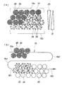
図3は第1実施形態の正電極層を構成する成分について説明する図である。
電解質膜12と正極拡散層15との間に正電極層13を備え、正極拡散層15に沿って酸素ガス流路18(図2も参照)を設ける。
なお、理解を容易にするために、酸素ガス流路18を便宜上、蛇行させたものとして説明する。
酸素ガス流路18には、供給側18aから排出側18bに向けて酸素ガスが流れる。
正電極層13には、主に電解質、カーボン、カーボンに担持させた触媒、造孔剤、造孔作用揮発性溶媒および撥水性樹脂を含んでいる。
【0038】
電解質としては、例えばフッ素系化合物が該当し、触媒は、例えば白金が該当する。
また、造孔剤としては、例えば導電性を備えた針状炭素繊維が該当し、造孔作用揮発性溶媒としては、例えばブタノール(ブチルアルコール)が該当する。
さらに、撥水性樹脂としては、例えばテトラフルオロエチレンが該当する。
【0039】
電解質、カーボンおよびカーボンに担持させた触媒は、発電反応に影響を与えるもので、これらの物質が増えると発電反応が高くなり、減ると発電反応が低くなる。
造孔剤は正電極層13の空孔率を変化させるもので、造孔剤を増やすことで空孔率を高めることができる。空孔率を調整することで、酸素ガスの拡散性や排水性をコントロールすることができる。
【0040】
造孔作用揮発性溶媒は、乾燥時に、揮発させることにより空孔を形成し、造孔剤と同じ役割を果たすものである。撥水性樹脂は、生成水の排水性を高めるものである。
すなわち、造孔剤、造孔作用揮発性溶媒および撥水性樹脂は、生成水の排出性に影響を与えるもので、これらの物質が減ると排水性が低くなり、増えると排水性が高くなる。
【0041】
電解質/カーボンの重量比およびカーボンに担持させた触媒量(以下、「触媒の担持量」という)を、第1の成分表示部25で示すように電解質膜12側から正極拡散層15側に向けて漸次減少させる。
また、電解質/カーボンの重量比および触媒の担持量を、第2の成分表示部26で示すように鉛直方向上側から下側に向けて漸次減少させる。
さらに、電解質/カーボンの重量比および触媒の担持量を、第3の成分表示部27で示すように酸素ガス流路18の供給側18aから排出側18bに向けて漸次減少させる。
【0042】
また、造孔剤量、造孔作用揮発性溶媒および撥水性樹脂量を、第4の成分表示部30で示すように電解質膜12側から正極拡散層15側に向けて漸次増加させる。
さらに、造孔剤量、造孔作用揮発性溶媒および撥水性樹脂量を、第5の成分表示部31で示すように、正電極層13の鉛直方向上側13aから下側13bに向けて漸次増加させる。
さらに、造孔剤量、造孔作用揮発性溶媒および撥水性樹脂量を、第6の成分表示部32で示すように酸素ガス流路18の供給側18aから排出側18bに向けて漸次増加させる。
【0043】
一方、電解質膜12に接触する面34(破線の///で示す領域)においては、電解質/カーボンの重量比、触媒の担持量、造孔剤量、造孔作用揮発性溶媒および撥水性樹脂量を均一にした。
【0044】
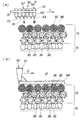
図4(a),(b)は本発明に係る燃料電池(第1実施形態)を構成する正電極層の成分を説明する図である。
(a)は、正電極層13のうちの、電解質膜に接触する面34(図3も参照)における、カーボンや、カーボンに担持させた触媒の状態を示す図である。
電解質膜に接触する面34、すなわち電解質膜12の近傍では、十分な触媒反応が要求される。
【0045】
よって、正電極層13のうち、電解質膜12の近傍において十分な触媒反応を可能にするために、大径のカーボン(カーボン)36・・・、小径のカーボン(カーボン)37・・・や、これらのカーボン36・・・,37・・・に担持させた触媒38・・・を多量で、かつ均一に含ませる。
具体的には、大径のカーボン36の表面に触媒38を密の状態に担持し、小径のカーボン37の表面に触媒38を密の状態に担持する。
これらのカーボン36,37を、電解質膜に接触する面34に密に含ませる。
【0046】
ところで、電解質膜に接触する面34、すなわち電解質膜12(図2、図3参照)の近傍では、触媒反応を十分に進行させる目的で、電解質膜12側の含水率を確保する必要がある。
よって、電解質膜に接触する面34において、造孔剤量、造孔作用揮発性溶媒および撥水性樹脂量を少量で、かつ均一に含ませる。
これにより、電解質膜12の近傍において、発電反応を十分に高めることができる。
【0047】
(b)は、正電極層13において、電解質膜12側から正極拡散層15側に向けて、電解質/カーボンの重量比および触媒38の担持量を漸次減少させた状態を示す図である。
具体的には、大径のカーボン36の表面に触媒38を密の状態に担持し、小径のカーボン37の表面に触媒38を密の状態に担持する。
【0048】
これらのカーボン36・・・,37・・・を、電解質膜12側から正極拡散層15側に向けて密の状態から粗の状態になるように含ませた。
よって、正電極層13において、電解質/カーボンの重量比および触媒38・・・の担持量を、第1の成分表示部25で示すように電解質膜12側から正極拡散層15側に向けて漸次減少させる。
【0049】
ここで、電解質膜12側では生成水の排水性を抑えて電解質膜12側の含水率を確保する必要がある。一方、正極拡散層15側では生成水の排水性を高くして正電極層13内の生成水を効率よく排水する必要がある。
よって、正電極層13に含む造孔剤量、造孔作用揮発性溶媒および撥水性樹脂量を、第4の成分表示部30で示すように電解質膜12側から正極拡散層15側に向けて漸次増加させる。
【0050】
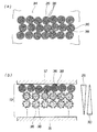
図5(a),(b)は本発明に係る燃料電池(第1実施形態)を構成する正電極層の成分を説明する図である。
(a)は、正電極層13の鉛直方向上側13aから下側13bに向けて、電解質/カーボンの重量比および触媒38の担持量を漸次減少させた状態を示す図である。
【0051】
具体的には、大径のカーボン36の表面に触媒38・・・を密の状態に担持したものを下側13bに向けて漸次減らすように含ませるとともに、大径のカーボン36の表面に触媒38・・・を粗の状態に担持したものを下側13bに向けて増やすように含ませた。
よって、正電極層13において、電解質/カーボンの重量比および触媒38の担持量を、第2の成分表示部26で示すように鉛直方向上側13aから下側13bに向けて漸次減少させる。
【0052】
ところで、正電極層13の下側13bには、生成水が自重により溜まりやすい。このため、正電極層13の下側13bにおいて生成水の排水性を高くし、生成水を効率よく排水する必要がある。
よって、正電極層13に含む造孔剤量、造孔作用揮発性溶媒および撥水性樹脂量を、第5の成分表示部31で示すように鉛直方向上側13aから下側13bに向けて漸次増加させる。
【0053】
(b)は、酸素ガス流路18の供給側18aから排出側18bに向けて、電解質/カーボンの重量比および触媒38の担持量を漸次減少させた状態を示す図である。
具体的には、大径のカーボン36の表面に触媒38・・・を密の状態に担持したものを酸素ガス流路18の供給側18aに含ませ、大径のカーボン36の表面に触媒38・・・を粗の状態に担持したものを酸素ガス流路18の中間分18cに含ませ、大径のカーボン36の表面に触媒38を担持しないものを酸素ガス流路18の排出側18bに含ませた。
よって、正電極層13において、電解質/カーボンの重量比および触媒38の担持量を、第3の成分表示部27(図3参照)で示すように酸素ガス流路18の供給側18aから排出側18bに向けて漸次減少させる。
【0054】
ところで、正電極層13内の生成水の一部は、酸素ガス流路18中に蒸散し、酸素ガスと共に移動する。
一方、酸素ガスは、酸素ガス流路18の屈曲部18dで酸素ガスが滞留しやすく、酸素ガス流路18の排出側18bにおいて酸素ガスの流量が減少しやすい。よって、酸素ガス流路18の排出側18bに生成水が溜まりやすい。
【0055】
このため、酸素ガス流路18の排出側18bにおいて生成水の排水性を高くし、生成水を効率よく排水する必要がある。
よって、正電極層13に含む造孔剤量、造孔作用揮発性溶媒および撥水性樹脂量を、第6の成分表示部32(図3参照)で示すように酸素ガス流路18の供給側18aから排出側18bに向けて漸次増加させる。
【0056】
図4(b)から図5に示すように、電解質/カーボンの重量比および触媒38の担持量を、電解質膜12側から正極拡散層15側に向けて減少させるとともに、鉛直方向上側13aから下側13bに向けて減少させ、かつ酸素ガス流路18の供給側18aから排出側18bに向けて減少させた。
これにより、電解質/カーボンの重量比および触媒38の担持量を多量に必要な部位には、これらの成分を多量に含ませて、各部位における発電効率を高めることができる。
【0057】
また、電解質/カーボンの重量比および触媒38の担持量を、少量しか必要としない部位には、これらの成分を少量含ませた。よって、これらの成分を過剰に含ませることを防止することができる。
これにより、正電極層13を構成する各成分の含有量を必要最小限に抑えることができる。
【0058】
一方、造孔剤量および撥水性樹脂量を、電解質膜12側から正極拡散層15側に向けて増加させるとともに、鉛直方向上側13aから下側13bに向けて増加させ、かつ酸素ガス流路18の供給側18aから排出側18bに向けて増加させた。
【0059】
よって、造孔剤量および撥水性樹脂量を、正電極層13のそれぞれの部位毎に好適に含ませて、各部位における生成水の排水性を好適に調整することができる。
これにより、造孔剤量および撥水性樹脂量を多量に必要な部位には、これらの成分を多量に含ませて、各部位における発電効率を高めることができる。
【0060】
また、造孔剤量および撥水性樹脂量を、少量しか必要としない部位には、これらの成分を少量含ませた。よって、これらの成分を過剰に含ませることを防止することができる。
これにより、正電極層を構成する各成分の含有量を必要最小限に抑えることができる。
【0061】
実施例
以下、燃料電池の具体例を表1、図6〜図10に基づいて説明する。
なお、正電極層の成分として、A〜Jの10種類の成分を用意した。A〜Jの成分については、表1、図6〜図8に詳しく示す。
【0062】
【表1】

ここで、表1に示す造孔剤および撥水性樹脂のそれぞれの割合は、固形分中の割合を示したものである。
ここで、固形分中の割合とは、電極を形成する単位体積あたりの全固形分重量のうち、それぞれの材料が占める重量の割合をいう。
【0064】
また、造孔作用揮発性溶媒の割合は溶媒中の割合を示したものである。
ここで、溶媒中の割合とは、単位体積あたりの電極を形成するときに用いる全溶媒重量のうちの、造孔用揮発性溶媒の重量割合をいう。
【0065】
成分Aは、電解質/カーボンの重量比を2.0、造孔剤の割合は5.0、造孔作用揮発性溶媒の割合を0、撥水性樹脂の割合を0、触媒の担持割合を49.1としたものである。
成分Bは、電解質/カーボンの重量比を1.8、造孔剤の割合は7.3、造孔作用揮発性溶媒の割合を7.5、撥水性樹脂の割合を4.8、触媒の担持割合を48.1としたものである。
【0066】
成分Cは、電解質/カーボンの重量比を1.6、造孔剤の割合は9.5、造孔作用揮発性溶媒の割合を14.0、撥水性樹脂の割合を9.4、触媒の担持割合を47.2としたものである。
成分Dは、電解質/カーボンの重量比を1.4、造孔剤の割合は11.6、造孔作用揮発性溶媒の割合を19.9、撥水性樹脂の割合を13.7、触媒の担持割合を46.2としたものである。
【0067】
成分Eは、電解質/カーボンの重量比を1.2、造孔剤の割合は13.6、造孔作用揮発性溶媒の割合を25.1、撥水性樹脂の割合を17.9、触媒の担持割合を45.7としたものである。
成分Fは、電解質/カーボンの重量比を1.0、造孔剤の割合は15.5、造孔作用揮発性溶媒の割合を29.8、撥水性樹脂の割合を21.9、触媒の担持割合を44.6としたものである。
【0068】
成分Gは、電解質/カーボンの重量比を0.9、造孔剤の割合は17.3、造孔作用揮発性溶媒の割合を32.8、撥水性樹脂の割合を23.6、触媒の担持割合を43.1としたものである。
成分Hは、電解質/カーボンの重量比を0.8、造孔剤の割合は19.1、造孔作用揮発性溶媒の割合を35.6、撥水性樹脂の割合を25.2、触媒の担持割合を41.0としたものである。
【0069】
成分Iは、電解質/カーボンの重量比を0.7、造孔剤の割合は20.8、造孔作用揮発性溶媒の割合を38.1、撥水性樹脂の割合を26.7、触媒の担持割合を38.4としたものである。
成分Jは、電解質/カーボンの重量比を0.6、造孔剤の割合は22.4、造孔作用揮発性溶媒の割合を40.6、撥水性樹脂の割合を28.2、触媒の担持割合を35.3としたものである。
【0070】
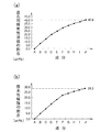
図6(a)は第1実施形態の正電極層に含有する電解質/カーボンの重量比を示すグラフであり、図6(b)は第1実施形態の正電極層に含有する造孔剤の割合を示すグラフである。
(a)の縦軸は電解質/カーボンの重量比を示し、横軸は各成分を示す。また、(b)の縦軸は造孔剤の割合を示し、横軸は各成分を示す。
【0071】
(a)に示すように、電解質/カーボンの重量比を0.6〜2.0の範囲とした(表1も参照)。
電解質/カーボンの重量比が0.6未満になると、電解質のカーボンへの被覆が少なくなり、十分な反応が得られない。
一方、電解質/カーボンの重量比が2.0を超えると、電解質成分が増え過ぎて生成水の拡散経路を塞いでしまい、さらには保水性が高くなり過ぎて、十分な反応が得られない。
そこで、電解質/カーボンの重量比を0.6〜2.0の範囲とした。
【0072】
(b)に示すように、造孔剤の割合を5.0〜22.4wt%の範囲とした(表1も参照)。
造孔剤の割合が5.0wt%未満になると、酸素ガスの拡散性が不十分になり、十分な発電反応を得ることが難しい。一方、造孔剤の割合が22.4wt%を超えると、正電極層13内のバインダー量が不足して、正電極層13の強度を確保することが難しい。
さらに、正電極層13内のバインダー量が不足することで、正電極層13内の成分の結合が不十分になることも起こり得る。
そこで、造孔剤の割合を5.0〜22.4wt%の範囲とした。
【0073】
図7(a)は第1実施形態の正電極層に含有する造孔作用揮発性溶媒の割合を示すグラフであり、図6(b)は第1実施形態の正電極層に含有する撥水性樹脂の割合を示すグラフである。
(a)の縦軸は造孔作用揮発性溶媒の割合を示し、横軸は各成分を示す。また、(b)の縦軸は撥水性樹脂の割合を示し、横軸は各成分を示す。
【0074】
(a)に示すように、造孔作用揮発性溶媒の割合を0〜40.6wt%の範囲とした(表1も参照)。
電解質膜12に接触する面34の近傍では、保水性が必要なため、造孔作用揮発性溶媒の割合の下限を0wt%とした。
一方、造孔作用揮発性溶媒の割合が40.6wt%を超えると、造孔剤と同様に、正電極層13内のバインダー量が不足して、正電極層13の強度を確保することが難しい。
さらに、正電極層13内のバインダー量が不足することで、正電極層13内の成分の結合が不十分になることも起こり得る。
そこで、造孔作用揮発性溶媒の割合を0〜40.6wt%の範囲とした。
【0075】
(b)に示すように、撥水性樹脂の割合を0〜28.2wt%の範囲とした(表1も参照)。
電解質膜12に接触する面34の近傍では、保水性が必要なため、撥水性樹脂の割合の下限を0wt%とした。
一方、撥水性樹脂の割合が40.6wt%を超えると、樹脂量が増えすぎて空孔の形成を妨害してしまう虞がある。
そこで、撥水性樹脂の割合を0〜40.6wt%の範囲とした。
なお、バインダー機能として電解質(イオン交換樹脂)と撥水性樹脂の量を一定にコントロールしている。
【0076】
図8は第1実施形態の正電極層に含有する触媒の割合を示すグラフであり、縦軸は触媒の割合を示し、横軸は各成分を示す。
【0077】
触媒の担持割合を35.3〜49.1wt%の範囲とした(表1も参照)。
触媒の担持割合が35.3wt%未満になると、反応に必要な触媒の総量が少なくなり、無反応酸素が生じる。
一方、触媒の担持割合が49.1wt%を超えると、触媒量が多くなり、反応に寄与しない触媒が生じる。
そこで、触媒の担持割合を35.3〜49.1wt%の範囲とした。
【0078】
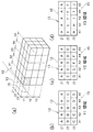
図9(a)〜(d)は第1実施形態の正電極層に含む成分の状態を示す第1説明図である。
(a)は、正電極層13を側面視で3行(Y1、Y2、Y3)、5列(X1、X2、X3、X4、x5)に仕き切るとともに、電解質膜12側から正極拡散層15側に向けて、Z1領域、Z2領域、Z3領域の3領域に仕き切った状態を示す。これにより、正電極層13を45個の部位に仕き切る。
【0079】
次に、(b)〜(d)において、Z1領域、Z2領域、Z3領域の成分について説明する。
なお、正電極層13の各部位の区別するために、例えば「///」で示した部位を、Z3(X1−Y1)とし、その他の部位も同様に表示する。
次に、(b)〜(d)において、Z1領域、Z2領域、Z3領域毎の成分について説明する。
なお、A〜Jの成分は、表1で説明した成分である。
【0080】
(b)は、Z1領域、すなわち電解質膜に接触する領域であり、部位Z1(X1−Y1)〜部位Z1(X5−Y3)の15の部位、すなわち全ての部位で、成分をAとした。
電解質膜に接触する領域では、十分な触媒反応が要求される。よって、正電極層13のうち、電解質膜12の近傍において十分な触媒反応を可能にするために、図4および図4(a)で説明したように、電解質/カーボン重量比や触媒の担持量を多く、かつ均一に含ませた。
【0081】
また、電解質膜に接触する領域では、触媒反応を十分に進行させる目的で、電解質膜12の含水率を確保する必要がある。
よって、電解質膜の近傍において、造孔剤量、造孔作用揮発性溶媒および撥水性樹脂量を少量で、かつ均一に含ませた。
【0082】
(c)は、Z2領域であり、部位Z2(X1−Y1)、部位Z2(X2−Y1)および部位Z2(X3−Y1)の3の部位で、成分をBとした。
部位Z2(X4−Y1)、部位Z2(X5−Y1)および部位Z2(X5−Y2)の3の部位で、成分をCとした。
部位Z2(X4−Y2)、部位Z2(X3−Y2)および部位Z2(X2−Y
【0083】
2)の3の部位で、成分をDとした。
部位Z2(X1−Y2)、部位Z2(X1−Y3)および部位Z2(X2−Y3)の3の部位で、成分をEとした。
部位Z2(X3−Y3)、部位Z2(X4−Y3)および部位Z2(X5−Y3)の3の部位で、成分をFとした。
【0084】
(d)は、Z3領域、すなわち正極拡散層に接触する領域であり、部位Z3(X1−Y1)および部位Z3(X2−Y1)の2の部位で、成分をCとした。
部位Z3(X3−Y1)および部位Z3(X4−Y1)の2の部位で、成分をDとした。
部位Z3(X5−Y1)および部位Z3(X5−Y2)の2の部位で、成分をEとした。
【0085】
部位Z3(X4−Y2)および部位Z3(X3−Y2)の2の部位で、成分をFとした。
部位Z3(X2−Y2)および部位Z3(X1−Y2)の2の部位で、成分をGとした。
【0086】
部位Z3(X1−Y3)および部位Z3(X2−Y3)の2の部位で、成分をHとした。
部位Z3(X3−Y3)および部位Z3(X4−Y3)の2の部位で、成分をIとした。
部位Z3(X5−Y3)の1の部位で、成分をJとした。
【0087】
これにより、Z2領域およびZ3領域を構成する各部位の成分(電解質/カーボン重量比や触媒の担持量)を、水素ガス流路18の供給側18aから排出側18bに向けて漸次減少するように含ませた。
よって、電解質/カーボン重量比や触媒の担持量を多量に必要とする部位には、これらの成分を多量含ませ、少量しか必要としない部位には、これらの成分を少量含ませることができる。
【0088】
また、Z2領域およびZ3領域を構成する各部位の成分(造孔剤量、造孔作用揮発性溶媒および撥水性樹脂量)を、水素ガス流路18の供給側18aから排出側18bに向けて漸次増加するように含ませた。
よって、造孔剤量、造孔作用揮発性溶媒および撥水性樹脂量を多量に必要とする部位には、これらの成分を多量含ませ、少量しか必要としない部位には、これらの成分を少量含ませることができる。
【0089】
一方、Z2領域およびZ3領域を構成する各部位の成分(電解質/カーボン重量比や触媒の担持量)を、正電極層13の上側13aから下側13bに向けて漸次減少するように含ませた。
よって、電解質/カーボン重量比や触媒の担持量を多量に必要とする部位には、これらの成分を多量含ませ、少量しか必要としない部位には、これらの成分を少量含ませることができる。
【0090】
また、Z2領域およびZ3領域を構成する各部位の成分(造孔剤量、造孔作用揮発性溶媒および撥水性樹脂量)を、正電極層13の上側13aから下側13bに向けて漸次増加するように含ませた。
よって、造孔剤量、造孔作用揮発性溶媒および撥水性樹脂量を多量に必要とする部位には、これらの成分を多量含ませ、少量しか必要としない部位には、これらの成分を少量含ませることができる。
【0091】
図10(a)〜(d)は第1実施形態の正電極層に含む成分の状態を示す第2説明図である。
(a)は、図9と同様に正電極層を側面視で3行(Y1、Y2、Y3)、5列(X1、X2、X3、X4、x5)に仕切るとともに、電解質膜12側から正極拡散層15側に向けて、Z1、Z2、Z3に仕き切った状態を示す。
これにより、正電極層を45個の部位に仕き切る。
【0092】
次に、(b)〜(d)において、Y1領域、Y2領域、Y3領域の成分について説明する。
なお、Y1領域、Y2領域、Y3領域の各部位の区別するために、例えば「///」で示した部位を、Y1(X1−Z3)とし、その他の部位も同様に表示する。このY1(X1−Z3)の部位は、図9で説明したZ3(X1−Y1)の部位と、表現方法を変えただけで同じ部位を示す。
次に、(b)〜(d)において、Y1領域、Y2領域、Y3領域毎の成分について説明する。
なお、A〜Jの成分は、表1で説明した成分である。
【0093】
(b)は、Y1領域、すなわち正電極層の上部となる領域であり、電解質膜側の部位Y1(X1−Z1)〜部位Y1(X5−Z1)の5の部位で、成分を全てAとした。
部位Y1(X1−Z2)、部位Y1(X2−Z2)および部位Y1(X3−Z2)の3の部位で、成分をBとした。
【0094】
部位Y1(X4−Z2)、部位Y1(X5−Z2)、部位Y1(X1−Z3)および部位Y1(X2−Z3)の4の部位で、成分をCとした。
部位Y1(X3−Z3)、部位Y1(X4−Z3)および部位Y1(X5−Z3)の3の部位で、成分をDとした。
【0095】
(c)は、Y2領域であり、部位Y2(X1−Z1)〜部位Y2(X5−Z1)の5の部位で、成分をAとした。
部位Y2(X1−Z2)の1の部位で、成分をEとした。
部位Y2(X2−Z2)、部位Y2(X3−Z2)および部位Y2(X4−Z2)の3の部位で、成分をDとした。
部位Y2(X5−Z2)の1の部位で、成分をCとした。
【0096】
部位Y2(X1−Z3)および部位Y2(X2−Z3)の2の部位で、成分をFとした。
部位Y2(X5−Z3)の1の部位で、成分をEとした。
【0097】
(d)は、Y3領域、すなわち正電極層の下部となる領域であり、電解質膜側の部位Y3(X1−Z1)〜部位Y3(X5−Z1)の5の部位で、成分を全てAとした。
部位Y3(X1−Z2)および部位Y3(X2−Z2)の2の部位で、成分をEとした。
【0098】
部位Y3(X3−Z2)、部位Y3(X4−Z2)および部位Y3(X5−Z2)の3の部位で、成分をFとした。
部位Y3(X1−Z3)および部位Y1(X2−Z3)の2の部位で、成分をHとした。
部位Y3(X3−Z3)および部位Y3(X4−Z3)の2の部位で、成分をIとした。
部位Y3(X5−Z3)の1の部位で、成分をJとした。
【0099】
これにより、Y1領域〜Y3領域を構成する各部位の成分(電解質/カーボン重量比や触媒の担持量)を、電解質膜12から正極拡散層15に向けて漸次減少するように含ませた。
よって、電解質/カーボン重量比や触媒の担持量を多量に必要とする部位には、これらの成分を多量含ませ、少量しか必要としない部位には、これらの成分を少量含ませることができる。
【0100】
また、Y1領域〜Y3領域を構成する各部位の成分(造孔剤量、造孔作用揮発性溶媒および撥水性樹脂量)を、電解質膜12から正極拡散層15に向けて漸次増加するように含ませた。
よって、造孔剤量、造孔作用揮発性溶媒および撥水性樹脂量を多量に必要とする部位には、これらの成分を多量含ませ、少量しか必要としない部位には、これらの成分を少量含ませることができる。
【0101】
次に、図9および図10に示す正電極層13を備えた燃料電池10の作用を図11〜図13に基づいて説明する。
図11(a)は第1実施形態の電解質膜、正電極層および正極拡散層を示す概略斜視図、図11(b)は第1実施形態の第1作用説明図であり、(b)は(a)の11b矢視図である。
(a)は、電解質膜12に正電極層13を積層し、正電極層13に正極拡散層15を積層したものである。
【0102】
(b)において、正極拡散層15を経て正電極層13内に酸素(O2)が矢印▲3▼の如く進入し、進入した酸素(O2)は正電極層13内から電解質膜12に入り込む。
一方、負電極層14(図2参照)内の反応で生成した水素イオン(H+)が電解質膜12を透過して、正電極層13側に矢印▲4▼の如く進入する。
よって、水素イオン(H+)と酸素(O2)とが反応して、生成水が生成される。
【0103】
ここで、水素イオン(H+)と酸素(O2)との反応は、正電極層13内のうち、特に電解質膜12に接触する面34(破線の///で示す領域)で進行する。
そこで、電解質膜12に接触する面34において、電解質/カーボンの重量比を大きく、触媒の担持量を多量に含ませるとともに、均一に含ませた。
よって、電解質膜12に接触する面34において、電極反応を十分に促進させることができる。
【0104】
さらに、電解質膜12に接触する面34において、造孔剤量、造孔作用揮発性溶媒および撥水性樹脂量を少量含ませるとともに、均一に含ませて、電解質膜12に接触する面34の排水性を抑えた。
よって、水素イオン(H+)と酸素(O2)とが反応して、生成された生成水が矢印▲5▼の如く正電極層13内に進入する際に、一部の生成水を電解質膜14側に矢印▲6▼の如く戻す。
これにより、電解質膜14を好適な湿潤状態に保ち、水素イオン(H+)と酸素(O2)との反応をより一層促進させることができる。
【0105】
ここで、水素イオン(H+)と酸素(O2)との反応は、電解質膜12側から正極拡散層15側に向けて漸次抑えられる。
そこで、水素イオン(H+)と酸素(O2)との反応状態に対応させて、電解質/カーボンの重量比および触媒の担持量を、第1の成分表示部25で示すように電解質膜12側から正極拡散層15側に向けて漸次減少させた。
よって、水素イオン(H+)と酸素(O2)との反応に悪影響を与えることなく、電解質、カーボンや触媒の担持量を減らすことができる。
【0106】
また、生成水は正極拡散層15側に向けて▲7▼の如く逃がすために、正極拡散層15の排水性は、電解質膜12側から正極拡散層15側に向けて漸次高くする必要がある。
そこで、排水性に対応させて、正電極層13に含む造孔剤量、造孔作用揮発性溶媒および撥水性樹脂量を、第4の成分表示部30で示すように電解質膜12側から正極拡散層15側に向けて漸次増加させた。
よって、生成水の排水性に悪影響を与えることなく、造孔剤量、造孔作用揮発性溶媒および撥水性樹脂量を減らすことができる。
【0107】
図12は第1実施形態の第2作用説明図である。
酸素ガス流路18(図3参照)の供給側18aは、正電極層13の上側13aに位置し、排出側18bは下側13bに位置する。
よって、正極拡散層15を経て正電極層13内に矢印▲3▼の如く進入する酸素(O2)量は、正電極層13の鉛直方向上側13aから下側13bに向けて漸次減少する。
【0108】
これにより、水素イオン(H+)と酸素(O2)との反応は、正電極層13の鉛直方向上側13aから下側13bに向けて漸次抑えられる。
そこで、水素イオン(H+)と酸素(O2)との反応状態に対応させて、電解質/カーボンの重量比および触媒の担持量を、第2の成分表示部26で示すように正電極層13の鉛直方向上側13aから下側13bに向けて漸次減少させた。
よって、水素イオン(H+)と酸素(O2)との反応に悪影響を与えることなく、電解質、カーボンや触媒の担持量を減らすことができる。
【0109】
また、正電極層13内の生成水は、正極拡散層15に矢印▲8▼の如く流出し、その他の生成水は自重で正電極層15内を矢印▲9▼の如く下降する。このため、下降した生成水を、正電極層13の下側13bから正極拡散層15に矢印の如く流出させる必要がある。
よって、生成水を効率よく正極拡散層15側に向けて逃がすために、正極拡散層15の排水性は、上側13aから下側13bに向けて漸次減少させる必要がある。
【0110】
そこで、排水性に対応させて、正電極層13に含む造孔剤量、造孔作用揮発性溶媒および撥水性樹脂量を、第5の成分表示部31で示すように上側13aから下側13bに向けて漸次増加させた。
よって、生成水の排水性に悪影響を与えることなく、造孔剤量、造孔作用揮発性溶媒および撥水性樹脂量を減らすことができる。
【0111】
図13は第1実施形態の第3作用説明図であり、(a)で電解質/カーボンの重量比および触媒の担持量について説明し、(b)で造孔剤量、造孔作用揮発性溶媒および撥水性樹脂量について説明する。
酸素ガスは酸素ガス流路18の供給側18aから排出側18bに向けて流れる。酸素ガス流路18内を流れる酸素ガスは、屈曲部18dで酸素ガスが滞留しやすく、酸素ガス流路18の排出側18bに向けて漸次減少しやすい。
よって、正極拡散層15を経て正電極層13(図12参照)内に進入する酸素(O2)量は、酸素ガス流路18の供給側18aから排出側18bに向けて漸次減少する。
【0112】
これにより、水素イオン(H+)と酸素(O2)との反応は、酸素ガス流路18の供給側18aから排出側18bに向けて漸次抑えられる。
そこで、水素イオン(H+)と酸素(O2)との反応状態に対応させて、電解質/カーボンの重量比および触媒の担持量を、第3の成分表示部27で示すように酸素ガス流路18の供給側18aから排出側18bに向けて漸次減少させた。
よって、水素イオン(H+)と酸素(O2)との反応に悪影響を与えることなく、電解質、カーボンや触媒の担持量を減らすことができる。
【0113】
また、正電極層13(図12参照)内の生成水の一部は、酸素ガス流路18中に蒸散し、酸素ガスと共に移動する。
一方、酸素ガスは、酸素ガス流路18の屈曲部18dで酸素ガスが滞留しやすく、酸素ガス流路18の排出側18bにおいて酸素ガスの流量が減少しやすく、酸素ガス流路18の排出側18bに生成水が溜まりやすい。
【0114】
このため、酸素ガス流路18の排出側18bにおいて生成水の排水性を高くし、生成水を効率よく排水する必要がある。
そこで、正電極層13に含む造孔剤量、造孔作用揮発性溶媒および撥水性樹脂量を、第6の成分表示部32で示すように酸素ガス流路18の供給側18aから排出側18bに向けて漸次増加させた。
よって、生成水の排水性に悪影響を与えることなく、造孔剤量、造孔作用揮発性溶媒および撥水性樹脂量を減らすことができる。
【0115】
図11〜図13に示すように、電解質/カーボンの重量比および触媒38の担持量を多量に必要な部位には、これらの成分を多量に含ませて、各部位における発電効率を高めることができる。
また、電解質/カーボンの重量比および触媒38の担持量を、少量しか必要としない部位には、これらの成分を少量含ませた。よって、これらの成分を過剰に含ませることを防止することができる。
これにより、正電極層13を構成する各成分の含有量を必要最小限に抑えることができる。
【0116】
一方、造孔剤量および撥水性樹脂量を多量に必要な部位には、これらの成分を多量に含ませて、各部位における発電効率を高めることができる。
また、造孔剤量および撥水性樹脂量を、少量しか必要としない部位には、これらの成分を少量含ませた。よって、これらの成分を過剰に含ませることを防止することができる。
これにより、正電極層を構成する各成分の含有量を必要最小限に抑えることができる。
【0117】
次に、燃料電池の第2実施形態を図14〜図15に基づいて説明する。なお、第2実施形態において第1実施形態と同一部材については同一符号を付して説明を省略する。
図14(a),(b)は本発明に係る第2実施形態の正電極層の成分を説明する図である。
(a)は、正電極層13のうちの、電解質膜に接触する面34(図3も参照)における、カーボンや、カーボンに担持させた触媒の状態を示す図である。
電解質膜に接触する面34、すなわち電解質膜12の近傍では、十分な触媒反応が要求される。
【0118】
よって、正電極層13のうち、電解質膜12の近傍において十分な触媒反応を可能にするために、大径のカーボン(カーボン)36・・・や、これらのカーボン36・・・に担持させた触媒38・・・を多量で、かつ均一に含ませる。
具体的には、大径のカーボン36の表面に触媒38を密の状態に担持させ、これらのカーボン36を、電解質膜に接触する面34に密に含ませる。
【0119】
なお、電解質膜に接触する面34における、造孔剤量、造孔作用揮発性溶媒および撥水性樹脂量は、第1実施形態と同様に調整する。
【0120】
(b)は、正電極層13において、電解質膜12側から正極拡散層15側に向けて、電解質/カーボンの重量比および触媒38の担持量を漸次減少させた状態を示す図である。
具体的には、大径のカーボン36の表面に触媒38を密の状態に担持する。
よって、正電極層13において、電解質/カーボンの重量比および触媒38・・・の担持量を、第1の成分表示部25で示すように電解質膜12側から正極拡散層15側に向けて漸次減少させる。
【0121】
なお、電解質膜に接触する面34における、造孔剤量、造孔作用揮発性溶媒および撥水性樹脂量は、第1実施形態と同様に調整する。
【0122】
図15は本発明に係る第2実施形態の正電極層の成分を説明する図である。
(a)は、正電極層13の鉛直方向上側13aから下側13bに向けて、電解質/カーボンの重量比および触媒38の担持量を漸次減少させた状態を示す図である。
【0123】
具体的には、大径のカーボン36を、正電極層13の鉛直方向上側13aから下側13bに向けて漸次減少させて含ませるとともに、大径のカーボン36の表面に担持する触媒38・・・を、正電極層13の鉛直方向上側13aから下側13bに向けて漸次減らすように含ませた。
よって、正電極層13において、電解質/カーボンの重量比および触媒38の担持量を、第2の成分表示部26で示すように鉛直方向上側13aから下側13bに向けて漸次減少させる。
【0124】
なお、電解質膜に接触する面34における、造孔剤量、造孔作用揮発性溶媒および撥水性樹脂量は、第1実施形態と同様に調整する。
【0125】
次に、燃料電池の製造方法について図16〜図18に基づいて説明する。なお、ここでは理解を容易にするために、造孔作用揮発性溶媒の説明は省略するが、造孔作用揮発性溶媒は造孔剤と同様に塗布するものとする。
図16は燃料電池の正電極層を塗布する塗布手段を示す側面図である。
塗布手段50は、保持部材51を備え、保持部材51の先端51a側から順に、電極用スラリー塗布部52、電解質塗布部57、造孔剤塗布部58、撥水性樹脂59を備える。
電極用スラリー塗布部52は、第1電極用スラリー塗布部53と、第2電極用スラリー塗布部54と、第3電極用スラリー塗布部55とからなる。
【0126】
第1電極用スラリー塗布部53は、タンク61内に、触媒を多量に含んだ第1電極スラリーを蓄えている。タンク61内のピエゾポンプ62を駆動することにより、第1電極用スラリーをノズル63から矢印の如く飛滴させるものである。
第2電極用スラリー塗布部54は、タンク65内に、触媒を中量に含んだ第2電極スラリーを蓄えている。タンク65内のピエゾポンプ66を駆動することにより、第2電極用スラリーをノズル67から矢印の如く飛滴させるものである。
【0127】
第3電極用スラリー塗布部55は、タンク68内に、触媒を少量に含んだ第3電極スラリーを蓄えている。タンク68内のピエゾポンプ69を駆動することにより、第3電極用スラリーをノズル71から矢印の如く飛滴させるものである。
【0128】
電解質塗布部57は、タンク72内に、電解質スラリーを蓄えている。タンク72内のピエゾポンプ73を駆動することにより、電解質スラリーをノズル74から矢印の如く飛滴させるものである。
【0129】
造孔剤塗布部58は、タンク76内に、造孔剤スラリーを蓄えている。タンク76内のピエゾポンプ77を駆動することにより、造孔剤スラリーをノズル78から矢印の如く飛滴させるものである。
【0130】
撥水性樹脂塗布部59は、タンク81内に、撥水性樹脂スラリーを蓄えている。タンク81内のピエゾポンプ82を駆動することにより、撥水性樹脂スラリーをノズル83から矢印の如く飛滴させるものである。
【0131】
この塗布手段50によれば、塗布部53,54,55,57,58,59に、それぞれピエゾポンプ62,66,69,73,77,82を使用することにより、各ノズル63,67,71,74,78,83からスラリーを飛滴させる際に、分散せずに粒状に付着させることができる。
【0132】
ピエゾポンプ62,66,69,73,77,82とは、ピエゾ素子をポンプの駆動源に用いたポンプである。
この塗布手段50に移動手段を備えて保持部材51を連続的に移動することで、塗布手段50を正極側拡散層15に沿って移動させて連続的な塗布が可能になる。
【0133】
図17(a),(b)は本発明に係る燃料電池の製造方法を示す第1工程説明図である。
(a)において、正極側拡散層15を配置し、正極側拡散層15上に塗布手段50を配置し、塗布手段50を待機位置Pから矢印Aの如く移動する。
塗布手段50の移動とともに、第3電極用スラリー塗布部55のピエゾポンプ69を駆動して、タンク68内の第3電極用スラリーをノズル71から矢印の如く飛滴する。
これにより、表面に触媒38・・・を粗の状態に担持した大径のカーボン36を正極側拡散層15上に塗布する。
【0134】
同時に、造孔剤塗布部58のピエゾポンプ77を駆動して、タンク76内の造孔剤スラリーをノズル78から矢印の如く多量飛滴する。
加えて、撥水性樹脂59のピエゾポンプ82を駆動して、タンク81内の撥水性樹脂スラリーをノズル83から矢印の如く多量飛滴する。
これにより、表面に触媒38を粗の状態に担持した大径のカーボン36とともに、正極側拡散層15上に造孔剤や撥水性樹脂をそれぞれ多量に塗布する。
塗布手段50の1回目の塗布完了後、塗布手段50を待機位置Pまで戻す。
【0135】
(b)において、塗布手段50を待機位置Pから矢印Bの如く移動する。
塗布手段50の移動とともに、第2電極用スラリー塗布部54のピエゾポンプ66を駆動して、タンク65内の第2電極用スラリーをノズル67から矢印の如く中量、すなわち第1電極用スラリーより多量に飛滴する。
これにより、表面に触媒38・・・を中程度の密の状態に担持した大径のカーボン36を、表面に触媒38・・・を粗の状態に担持した大径のカーボン36上に中量、すなわち第1電極用スラリーより多量に塗布する。
【0136】
同時に、電解質塗布部57のピエゾポンプ73を駆動して、タンク72内の電解質スラリーをノズル74から矢印の如く飛滴する。
さらに、造孔剤塗布部58のピエゾポンプ77を駆動して、タンク76内の造孔剤スラリーをノズル78から矢印の如く、1回目の造孔剤スラリーより少量飛滴する。
【0137】
加えて、撥水性樹脂59のピエゾポンプ82を駆動して、タンク81内の撥水性樹脂スラリーをノズル83から矢印の如く、1回目の撥水性樹脂スラリーより少量飛滴する。
これにより、表面に触媒38・・・を中程度の密の状態に担持した大径のカーボン36とともに、表面に触媒38を粗の状態に担持した大径のカーボン36上に、造孔剤や撥水性樹脂を少量塗布する。
塗布手段50の2回目の塗布完了後、塗布手段50を待機位置Pまで戻す。
【0138】
図18(a),(b)は本発明に係る燃料電池の製造方法を示す第2工程説明図である。
(a)において、塗布手段50を待機位置Pから矢印Cの如く移動する。
塗布手段50の移動とともに、第1電極用スラリー塗布部53のピエゾポンプ62を駆動して、タンク61内の第1電極用スラリーをノズル63から矢印の如く多量に、すなわち第2電極用スラリーより多量に飛滴する。
これにより、表面に触媒38・・・を密の状態に担持した大径のカーボン36を、表面に触媒38・・・を中程度の密の状態に担持した大径のカーボン36上に、第2電極用スラリーより多量に塗布する。
【0139】
同時に、電解質塗布部57のピエゾポンプ73を駆動して、タンク72内の電解質スラリーをノズル74から矢印の如く、1回目の電解質スラリーより多量に飛滴する。
これにより、図14(b)に示すように、正電極層13に、電解質膜12側から正極拡散層15側に向けて、電解質/カーボンの重量比および触媒38の担持量を漸次減少させた状態に含有させることができる。
加えて、正電極層13に、造孔剤量、撥水性樹脂量を電解質膜12側から正極拡散層15側に向けて漸次増加させることができる。
【0140】
(b)において、表面に触媒38・・・を密の状態に担持した大径のカーボン36を、複数個配置して形成した上面84に、コーター90を矢印Dの如く移動する。このコーター90で、表面に触媒38・・・を密の状態に担持した大径のカーボン36の上面84上に電解質膜(イオン交換膜)12用のペーストを塗布して電解質膜12を形成する。
【0141】
具体的には、コーター90のブレード91を、カーボン36の上面84から上方に所定間隔離して上面84に平行に配置する。このブレード91を上面84に沿って矢印Dの如く移動しながら、ブレード91で電解質膜12のペーストを一定の厚さにならすことにより電解質膜12を形成する。
【0142】
図17〜図18に示す工程では、電解質膜12側から正極拡散層15側に向けて、正電極層13内の電解質/カーボンの重量比および触媒38の担持量を漸次減少させ、さらに正電極層13内の造孔剤量、撥水性樹脂量を漸次増加させる例について説明したが、この塗布工程に、マスキングを用いることで、図9〜図10に示すように、正電極層13を複数の部位(一例として、45個の部位)毎に成分を異ならせて塗布することが可能である。
【0143】
また、塗布手段50にピエゾポンプ62,66,69,73,77,82を使用することで、ノズルからスラリーを分散せずに粒状に付着させることができる。
よって、図9および図10に示すように、正電極部13を複数の部位に区分けした場合、これらの部位に相当する塗布部を備えることで、マスキングを用いることなく、正電極層13の複数の部位毎に成分を任意に決めることが可能である。
【0144】
さらに、塗布手段50は、各成分毎にタンクを個別に設け、ピエゾポンプ62,66,69,73,77,82で塗布するように構成したので、正電極層13を構成する複数の部位における成分の変化を段階的変化ではなく、連続的に変化させることが可能になる。
【0145】
この塗布手段50を用いて、図17〜図18に示す塗布工程を実施することで、正電極層13の成分を、図3に示すように、電解質/カーボンの重量比およびカーボンに担持させた触媒量(以下、「触媒の担持量」という)を、第1の成分表示部25のように電解質膜12側から正極拡散層15側に向けて漸次減少させることが可能になる。
【0146】
また、電解質/カーボンの重量比および触媒の担持量を、第2の成分表示部26のように鉛直方向上側から下側に向けて漸次減少させることが可能になる。
さらに、電解質/カーボンの重量比および触媒の担持量を、第3の成分表示部27のように酸素ガス流路18の供給側18aから排出側18bに向けて漸次減少させることが可能になる。
【0147】
また、造孔剤量、造孔作用揮発性溶媒および撥水性樹脂量を、第4の成分表示部30のように電解質膜12側から正極拡散層15側に向けて漸次増加させることが可能になる。
さらに、造孔剤量、造孔作用揮発性溶媒および撥水性樹脂量を、第5の成分表示部31のように、正電極層13の鉛直方向上側13aから下側13bに向けて漸次増加させることが可能になる。
【0148】
また、造孔剤量、造孔作用揮発性溶媒および撥水性樹脂量を、第6の成分表示部32のように酸素ガス流路18の供給側18aから排出側18bに向けて漸次増加させることが可能になる。
加えて、電解質膜12に接触する面34(破線の///で示す領域)においては、電解質/カーボンの重量比、触媒の担持量、造孔剤量、造孔作用揮発性溶媒および撥水性樹脂量を均一にすることが可能になる。
【0149】
なお、前記実施形態では、塗布手段50にピエゾポンプ62,66,69,73,77,82を用いた例について説明したが、塗布手段50として通常のインクジェットを採用することも可能である。
インクジェットは塗布範囲を絞り込むことができるので、正電極層13を構成する複数の部位に好適にスラリーを塗布することができる。
【0150】
また、前記実施形態では、塗布手段50の各スラリー塗布部53,54,55,57,58,59に噴射用のノズル63,67,71,74,78,83を個別に設け、それぞれのノズルから、各スラリーを個別に飛滴させる例について説明したが、その他の例として、噴射用の各ノズル63,67,71,74,78,83を互いに連通させ、連通させたノズル内で各スラリーを混合させた後、混合状態のスラリーを飛滴させることも可能である。
【0151】
【発明の効果】
本発明は上記構成により次の効果を発揮する。
請求項1は、電解質/カーボンの重量比、触媒の担持量、造孔剤量および撥水性樹脂量を、電解質膜側から正極拡散層側に向けて漸次変化させた。
また、電解質/カーボンの重量比、触媒の担持量、造孔剤量および撥水性樹脂量を、鉛直方向上側から下側に向けて漸次変化させた。
さらに、電解質/カーボンの重量比、触媒の担持量、造孔剤量および撥水性樹脂量を、前記酸素ガス流路の供給側から排出側に向けて漸次変化させた。
【0152】
よって、電極層のそれぞれの成分を、酸素ガスの導入状態に応じて漸次変化させ、水素イオン(H+)と酸素(O2)との反応状態に応じて漸次変化させ、生成水の排水状態に応じて漸次変化させることができる。
これにより、正電極層を構成する各成分を、正電極層のそれぞれの部位に合わせて好適に含ませて、各部位における発電効率を高めることや、生成水の排水性を好適に調整することができる。
【0153】
また、正電極層を構成する各成分を、正電極層のそれぞれの部位に合わせて好適に含ませることで、過剰に含ませることを防止することができる。
これにより、正電極層を構成する各成分の含有量を必要最小限に抑えることができ、コスト低減を図ることが可能になる。
【0154】
さらに、請求項1は、電解質/カーボンの重量比および触媒の担持量を、電解質膜側から正極拡散層側に向けて減少させるとともに、鉛直方向上側から下側に向けて減少させ、かつ酸素ガス流路の供給側から排出側に向けて減少させた。
これにより、電解質/カーボンの重量比および触媒の担持量を多量に必要な部位には、これらの成分を多量に含ませて、各部位における発電効率を高めることができる。
【0155】
また、電解質/カーボンの重量比および触媒の担持量を、少量しか必要としない部位には、これらの成分を少量含ませた。よって、これらの成分を過剰に含ませることを防止することができる。
これにより、正電極層を構成する各成分の含有量を必要最小限に抑えることができ、コスト低減を図ることが可能になる。
【0156】
一方、造孔剤量および撥水性樹脂量を、電解質膜側から正極拡散層側に向けて増加させるとともに、鉛直方向上側から下側に向けて増加させ、かつ酸素ガス流路の供給側から排出側に向けて増加させた。
これにより、造孔剤量および撥水性樹脂量を、正電極層のそれぞれの部位毎に好適に含ませて、各部位における生成水の排水性を好適に調整することができる。
したがって、造孔剤量および撥水性樹脂量を多量に必要な部位には、これらの成分を多量に含ませて、各部位における発電効率を高めることができる。
【0157】
また、造孔剤量および撥水性樹脂量を、少量しか必要としない部位には、これらの成分を少量含ませた。よって、これらの成分を過剰に含ませることを防止することができる。
これにより、正電極層を構成する各成分の含有量を必要最小限に抑えることができ、コスト低減を図ることが可能になる。
【0158】
請求項2は、電解質膜に接触する面において、十分な触媒反応が可能で、かつ電解質膜側の含水率の確保が可能なように、正電極層の各成分をそれぞれ均一に含ませた。
これにより、電解質膜の近傍において、発電反応を十分に高めることができる。
【図面の簡単な説明】
【図1】本発明に係る燃料電池(第1実施形態)を示す斜視図
【図2】本発明に係る燃料電池(第1実施形態)の断面図
【図3】第1実施形態の正電極層を構成する成分について説明する図
【図4】本発明に係る燃料電池(第1実施形態)を構成する正電極層の成分を説明する図
【図5】本発明に係る燃料電池(第1実施形態)を構成する正電極層の成分を説明する図
【図6】(a)は第1実施形態の正電極層に含有する電解質/カーボンの重量比を示すグラフ、(b)は第1実施形態の正電極層に含有する造孔剤の割合を示すグラフ
【図7】(a)は第1実施形態の正電極層に含有する造孔作用揮発性溶媒の割合を示すグラフ、(b)は第1実施形態の正電極層に含有する撥水性樹脂の割合を示すグラフ
【図8】第1実施形態の正電極層に含有する触媒の割合を示すグラフ
【図9】第1実施形態の正電極層に含む成分の状態を示す第1説明図
【図10】第1実施形態の正電極層に含む成分の状態を示す第2説明図
【図11】(a)は第1実施形態の電解質膜、正電極層および正極拡散層を示す概略斜視図、図11(b)は第1実施形態の第1作用説明図
【図12】第1実施形態の第2作用説明図
【図13】第1実施形態の第3作用説明図
【図14】本発明に係る第2実施形態の正電極層の成分を説明する図
【図15】本発明に係る第2実施形態の正電極層の成分を説明する図
【図16】燃料電池の正電極層を塗布する塗布手段を示す側面図
【図17】本発明に係る燃料電池の製造方法を示す第1工程説明図
【図18】本発明に係る燃料電池の製造方法を示す第2工程説明図
【図19】従来の燃料電池の要部を説明する図
【図20】従来の燃料電池の要部を示す断面図
【図21】従来の燃料電池の要部を示す側面図
【符号の説明】
10…燃料電池、11…セル、12…電解質膜、13…正電極層、13a…正電極層の上側、13b…正電極層の下側、14…負電極層、15…正極拡散層、17…セパレータ、18…酸素ガス流路、18a…酸素ガス流路の供給側、18b…酸素ガス流路の排出側、25…第1の成分表示部、26…第2の成分表示部、27…第3の成分表示部、30…第4の成分表示部、31…第5の成分表示部、32…第6の成分表示部、34…電解質膜に接触する面、36,37…カーボン、38…触媒。[0001]
BACKGROUND OF THE INVENTION
The present invention relates to a fuel cell that generates power by laminating a positive electrode layer and a negative electrode layer on the front and back surfaces of an electrolyte membrane, bringing hydrogen into contact with the catalyst in the negative electrode layer and oxygen in contact with the catalyst in the positive electrode layer. .
[0002]
[Prior art]
FIG. 19 is a diagram for explaining a main part of a conventional fuel cell.
Positive and
Oxygen gas flows from the
[0003]
By flowing oxygen gas through the oxygen
[0004]
FIG. 20 is a cross-sectional view showing a main part of a conventional fuel cell.
Hydrogen ions generated by the reaction in the negative electrode layer 103 (see FIG. 19) (H+) Passes through the
On the other hand, oxygen gas flows from the
[0005]
Therefore, hydrogen ions (H+) And oxygen (O2) Reacts with water (H2O) is generated. Hydrogen ion (H+) And oxygen (O2) In the area near the
[0006]
Generated water (H2O), a part of the generated water is returned to the
The remaining generated water (H2O) is partly discharged from the
For this reason, the generated water (H2O) tends to accumulate, which has been an obstacle to increasing the power generation efficiency of the fuel cell.
[0007]
FIG. 21 is a side view showing a main part of a conventional fuel cell.
Oxygen gas flows through the oxygen gas flow path 16 from the
On the other hand, the generated water flowing from the
[0008]
Here, oxygen gas tends to stay in the
For this reason, on the
[0009]
As described in FIG. 20, in the “sufficient catalytic reaction area” 102a, hydrogen ions (H+) And oxygen (O2In particular, a fuel cell in which the electrolytic mass in the positive electrode layer is increased on the electrolyte membrane side is known (see, for example, Patent Document 1).
[0010]
In addition, as described with reference to FIGS. 20 and 21, it should be noted that the retention of the generated water hinders the increase in power generation efficiency.2There is known a fuel cell in which O) is efficiently discharged from the positive electrode layer (see, for example, Patent Document 2).
Furthermore, as described with reference to FIG. 20, there has been known a fuel cell in which the
[0011]
[Patent Document 1]
Japanese Patent Laid-Open No. 8-88008 (first page, FIG. 4)
[Patent Document 2]
Japanese Patent Application Laid-Open No. 2002-289859 (second page, FIG. 1)
[Patent Document 3]
JP 2002-42823 A (page 3-4, FIG. 4)
[0012]
According to the fuel cell of Patent Document 1, a large amount of electrolytic mass in the positive electrode layer is included in the vicinity of the interface with the electrolyte membrane, and hydrogen ions (H+) Conductivity can be increased.
According to the fuel cell of
According to the fuel cell of
[0013]
[Problems to be solved by the invention]
Here, in order to further expand the applicability of the fuel cell, it is also important to enhance the performance of the fuel cell and reduce the cost of the fuel cell.
However, it is difficult to further improve the performance of the fuel cell and reduce the cost of the fuel cell only with a configuration in which a large amount of electrolytic mass is contained in the vicinity of the interface with the electrolyte membrane as in the fuel cell of Patent Document 1.
[0014]
Further, as in the fuel cell of
[0015]
Further, as in the fuel cell of
[0016]
Accordingly, an object of the present invention is to provide a fuel cell that is excellent in power generation efficiency and can be reduced in cost.
[0017]
[Means for Solving the Problems]
While conducting experiments to increase the power generation efficiency of fuel cells, we discovered that there are places in the positive electrode layer where oxygen gas can be easily introduced and where it is difficult to introduce. In addition, hydrogen ions (H+) And oxygen (O2) Was found to be easy to progress and slowly progressing. Furthermore, it discovered that there exists a site | part in which produced water tends to stay.
[0018]
Examining the above relationship in more detail, the power generation reaction and the retention of generated water tend to gradually change from the electrolyte membrane side to the positive electrode diffusion layer side, and further from the supply side to the discharge side of the oxygen gas flow path. It turned out that there is a tendency to change gradually.
Further, it was also found that when the positive electrode layer is vertically arranged and used, the power generation reaction and the retention of generated water tend to gradually change from the upper side to the lower side of the positive electrode layer.
[0019]
From these viewpoints, the components in the positive electrode layer, that is, the electrolyte, catalyst, pore former, etc., are gradually changed from the electrolyte membrane side to the positive electrode diffusion layer side, and gradually changed from the vertical upper side to the lower side. Moreover, the prospect that the problem could be solved by gradually changing from the supply side to the discharge side of the oxygen gas flow path was obtained.
[0020]
Specifically, in claim 1, positive and negative electrode layers are respectively laminated on the front and back surfaces of the electrolyte membrane, a positive electrode diffusion layer is laminated on the positive electrode layer, and a negative electrode diffusion layer is laminated on the negative electrode layer. In the fuel cell in which an oxygen gas flow path is provided outside the diffusion layer, a hydrogen gas flow path is provided outside the negative electrode diffusion layer, and the positive electrode layer is arranged in a vertical direction, an electrolyte is provided in the positive electrode layer. , Carbon, a catalyst supported on carbon, a pore-forming agent, and a water-repellent resin, and the weight ratio of the electrolyte / carbon, the amount of catalyst supported, the amount of pore-forming agent, and the amount of the water-repellent resin are determined from the electrolyte membrane side. While gradually changing toward the positive electrode diffusion layer side, gradually changing from the upper side in the vertical direction toward the lower side, and gradually changing from the supply side to the discharge side of the oxygen gas flow path.In the fuel cell, the weight ratio of the electrolyte / carbon and the supported amount of the catalyst are decreased from the electrolyte membrane side toward the positive electrode diffusion layer side and decreased from the upper side in the vertical direction toward the lower side. And the amount of the pore-forming agent and the amount of the water-repellent resin are increased from the electrolyte membrane side to the positive electrode diffusion layer side, while being decreased from the supply side to the discharge side of the oxygen gas flow path. From the supply side of the oxygen gas flow path to the discharge sideIt is characterized by that.
[0021]
The weight ratio of electrolyte / carbon, the amount of catalyst supported, the amount of pore-forming agent, and the amount of water-repellent resin were gradually changed from the electrolyte membrane side to the positive electrode diffusion layer side.
The weight ratio of electrolyte / carbon, the amount of catalyst supported, the amount of pore-forming agent, and the amount of water-repellent resin were gradually changed from the upper side to the lower side in the vertical direction.
Furthermore, the weight ratio of electrolyte / carbon, the amount of catalyst supported, the amount of pore-forming agent, and the amount of water-repellent resin were gradually changed from the supply side to the discharge side of the oxygen gas flow path.
[0022]
Therefore, each component of the electrode layer is gradually changed according to the state of introduction of oxygen gas, and hydrogen ions (H+) And oxygen (O2) And gradually change according to the drainage state of the generated water.
Moreover, it can prevent containing excessively by containing each component which comprises a positive electrode layer according to each site | part of a positive electrode layer suitably.
[0023]
further,Claim1Reduces the weight ratio of the electrolyte / carbon and the supported amount of the catalyst from the electrolyte membrane side to the positive electrode diffusion layer side, and decreases from the upper side to the lower side in the vertical direction, and the supply side of the oxygen gas channel The amount of pore-forming agent and water-repellent resin is increased from the electrolyte membrane side to the positive electrode diffusion layer side, and is increased from the upper side to the lower side in the vertical direction, and oxygen gas. Increase from the supply side to the discharge side of the flow pathIt was.
The reason for this will be described next.
[0024]
Here, the power generation reaction proceeds particularly at the boundary between the electrolyte membrane and the positive electrode layer, and gradually decreases from the boundary toward the positive electrode diffusion layer side.
In addition, the power generation reaction proceeds particularly at the upper end of the positive electrode layer, and gradually decreases from the upper side to the lower side.
Furthermore, the power generation reaction proceeds particularly on the supply side of the oxygen gas flow path, and gradually decreases from the supply side to the discharge side.
[0025]
Therefore, the claim1The weight ratio of the electrolyte / carbon and the amount of the catalyst supported are decreased from the electrolyte membrane side toward the positive electrode diffusion layer side, and are decreased from the upper side in the vertical direction toward the lower side, and the supply side of the oxygen gas channel Decreased toward the discharge side.
[0026]
Accordingly, a large amount of these components can be contained in a portion that requires a large amount of the electrolyte / carbon weight ratio and the supported amount of the catalyst, and the power generation efficiency at each portion can be increased.
Further, a small amount of these components was contained in a site where only a small amount of the electrolyte / carbon weight ratio and the amount of catalyst supported were required. Therefore, it can prevent containing these components excessively.
[0027]
On the other hand, the generated water needs to suppress drainage on the electrolyte membrane side in order to ensure the moisture content of the electrolyte membrane, and drainage on the positive electrode diffusion layer side to discharge generated water in the positive electrode layer. Need to be increased.
Further, since the generated water tends to stay on the lower end side of the positive electrode layer, it is necessary to gradually improve drainage from the upper side to the lower side.
Furthermore, since the generated water tends to stay on the discharge side of the oxygen gas flow path, it is necessary to gradually improve drainage from the supply side to the discharge side.
[0028]
Therefore, the claim1The amount of pore-forming agent and the amount of water-repellent resin are increased from the electrolyte membrane side to the positive electrode diffusion layer side, and are increased from the upper side to the lower side in the vertical direction and discharged from the supply side of the oxygen gas flow path. Increased towards the side.
Thereby, the amount of pore forming agents and the amount of water-repellent resin can be suitably included for each part of the positive electrode layer, and the drainage of the generated water at each part can be suitably adjusted.
Therefore, a large amount of these components can be contained in a site that requires a large amount of pore-forming agent and water-repellent resin.
[0029]
Further, a small amount of these components was contained in a site that required only a small amount of pore-forming agent and water-repellent resin. Therefore, it can prevent containing these components excessively.
[0030]
Claim2Is characterized in that the electrolyte / carbon weight ratio, the amount of catalyst supported, the amount of pore-forming agent, and the amount of water-repellent resin are made uniform on the surface in contact with the electrolyte membrane.
[0031]
Here, a sufficient catalytic reaction is required in the vicinity of the electrolyte membrane. In addition, it is necessary to ensure the moisture content on the electrolyte membrane side in order to sufficiently advance the catalytic reaction.
Therefore, in the vicinity of the electrolyte membrane, each component of the positive electrode layer was uniformly contained so that a sufficient catalytic reaction was possible and the moisture content on the electrolyte membrane side could be secured.
Thus, the power generation reaction is sufficiently increased in the vicinity of the electrolyte membrane.
[0032]
DETAILED DESCRIPTION OF THE INVENTION
Embodiments of the present invention will be described below with reference to the accompanying drawings.
FIG. 1 is a perspective view showing a fuel cell (first embodiment) according to the present invention, in which a cell is disassembled.
The
[0033]
The
[0034]
FIG. 2 is a cross-sectional view of the fuel cell (first embodiment) according to the present invention. Specifically, the cell is shown in cross section.
A
[0035]
By supplying oxygen gas to the oxygen
On the other hand, hydrogen ions generated by the reaction in the negative electrode layer 14 (H+) Permeates the
Therefore, hydrogen ions (H+) And oxygen (O2) Reacts with it to produce water. Hydrogen ion (H+) And oxygen (O2) Proceeds in the
[0036]
A part of the generated water is returned to the
Among the remaining generated water, a part flows out from the
[0037]
FIG. 3 is a diagram for explaining the components constituting the positive electrode layer of the first embodiment.
A
For ease of understanding, the oxygen
In the oxygen
The
[0038]
The electrolyte corresponds to, for example, a fluorine compound, and the catalyst corresponds to, for example, platinum.
Further, as the pore forming agent, for example, acicular carbon fibers having conductivity are applicable, and as the pore forming volatile solvent, for example, butanol (butyl alcohol) is applicable.
Furthermore, for example, tetrafluoroethylene corresponds to the water repellent resin.
[0039]
The electrolyte, carbon, and the catalyst supported on the carbon affect the power generation reaction. When these substances increase, the power generation reaction increases, and when the amount decreases, the power generation reaction decreases.
The pore former changes the porosity of the
[0040]
The pore-forming volatile solvent forms pores by volatilizing during drying, and plays the same role as the pore-forming agent. The water repellent resin enhances the drainage of the generated water.
That is, the pore-forming agent, the pore-forming volatile solvent, and the water-repellent resin affect the discharge property of the generated water. When these substances are reduced, the drainage property is lowered, and when it is increased, the drainage property is enhanced.
[0041]
The weight ratio of electrolyte / carbon and the amount of catalyst supported on carbon (hereinafter referred to as “the amount of catalyst supported”) are directed from the
Further, the weight ratio of the electrolyte / carbon and the supported amount of the catalyst are gradually decreased from the upper side to the lower side in the vertical direction as indicated by the second
Further, the weight ratio of the electrolyte / carbon and the supported amount of the catalyst are gradually decreased from the
[0042]
Further, the amount of pore-forming agent, the pore-forming volatile solvent, and the amount of water-repellent resin are gradually increased from the
Further, the amount of pore-forming agent, the pore-forming volatile solvent, and the amount of water-repellent resin are gradually increased from the vertical
Further, the amount of pore-forming agent, the pore-forming volatile solvent, and the amount of water-repellent resin are gradually increased from the
[0043]
On the other hand, on the surface 34 (area indicated by the broken line ///) in contact with the
[0044]
FIGS. 4A and 4B are diagrams illustrating components of the positive electrode layer constituting the fuel cell (first embodiment) according to the present invention.
(A) is a figure which shows the state of the catalyst supported on carbon in the surface 34 (refer also FIG. 3) of the
A sufficient catalytic reaction is required on the
[0045]
Therefore, in order to enable a sufficient catalytic reaction in the vicinity of the
Specifically, the
These
[0046]
By the way, in the vicinity of the
Therefore, the
Thereby, the power generation reaction can be sufficiently enhanced in the vicinity of the
[0047]
(B) is a diagram showing a state in which the weight ratio of the electrolyte / carbon and the amount of catalyst supported on the
Specifically, the
[0048]
These
Therefore, in the
[0049]
Here, on the
Therefore, the amount of pore-forming agent, the pore-forming volatile solvent and the amount of water-repellent resin contained in the
[0050]
FIGS. 5A and 5B are diagrams illustrating components of the positive electrode layer constituting the fuel cell (first embodiment) according to the present invention.
(A) is a figure which shows the state which decreased the weight ratio of electrolyte / carbon and the load of the
[0051]
Specifically, a catalyst in which the
Therefore, in the
[0052]
By the way, the generated water tends to accumulate on the
Therefore, the amount of pore-forming agent, the pore-forming volatile solvent, and the amount of water-repellent resin contained in the
[0053]
(B) is a diagram showing a state in which the weight ratio of the electrolyte / carbon and the amount of catalyst supported are gradually decreased from the
Specifically, the
Therefore, in the
[0054]
By the way, a part of the generated water in the
On the other hand, oxygen gas tends to stay in the
[0055]
For this reason, it is necessary to increase the drainage of the generated water on the
Therefore, the amount of pore-forming agent, the pore-forming volatile solvent, and the amount of water-repellent resin contained in the
[0056]
As shown in FIGS. 4B to 5, the weight ratio of the electrolyte / carbon and the amount of the
Thus, a large amount of these components can be contained in a portion that requires a large amount of the electrolyte / carbon weight ratio and the amount of the
[0057]
Further, a small amount of these components was contained in a site where only a small amount of the electrolyte / carbon weight ratio and the supported amount of the
Thereby, content of each component which comprises the
[0058]
On the other hand, the amount of pore-forming agent and the amount of water-repellent resin are increased from the
[0059]
Therefore, the amount of pore-forming agent and the amount of water-repellent resin can be suitably included for each part of the
Thereby, the site | part which requires a lot of pore-forming agent amount and water-repellent-resin amount can contain these components in large quantities, and can improve the electric power generation efficiency in each site | part.
[0060]
Further, a small amount of these components was contained in a site that required only a small amount of pore-forming agent and water-repellent resin. Therefore, it can prevent containing these components excessively.
Thereby, content of each component which comprises a positive electrode layer can be suppressed to required minimum.
[0061]
Example
Hereinafter, specific examples of the fuel cell will be described with reference to Table 1 and FIGS.
In addition, 10 types of components A to J were prepared as components of the positive electrode layer. The components A to J are shown in detail in Table 1 and FIGS.
[0062]
[Table 1]
Here, the ratios of the pore-forming agent and the water-repellent resin shown in Table 1 indicate the ratio in the solid content.
Here, the ratio in solid content means the ratio of the weight which each material occupies among the total solid content weight per unit volume which forms an electrode.
[0064]
In addition, the ratio of the pore-forming volatile solvent indicates the ratio in the solvent.
Here, the ratio in the solvent means the weight ratio of the volatile solvent for pore formation out of the total solvent weight used when forming the electrode per unit volume.
[0065]
Component A has an electrolyte / carbon weight ratio of 2.0, a pore-forming agent ratio of 5.0, a pore-forming volatile solvent ratio of 0, a water-repellent resin ratio of 0, and a catalyst loading ratio of 49. .1.
Component B has an electrolyte / carbon weight ratio of 1.8, a pore-forming ratio of 7.3, a pore-forming volatile solvent ratio of 7.5, a water-repellent resin ratio of 4.8, The loading ratio is 48.1.
[0066]
Component C has an electrolyte / carbon weight ratio of 1.6, a pore-forming ratio of 9.5, a pore-forming volatile solvent ratio of 14.0, a water-repellent resin ratio of 9.4, The loading ratio is 47.2.
Component D has an electrolyte / carbon weight ratio of 1.4, a pore-forming ratio of 11.6, a pore-forming volatile solvent ratio of 19.9, a water-repellent resin ratio of 13.7, The loading ratio is 46.2.
[0067]
Component E has an electrolyte / carbon weight ratio of 1.2, a pore-forming ratio of 13.6, a pore-forming volatile solvent ratio of 25.1, a water-repellent resin ratio of 17.9, The loading ratio is 45.7.
Component F has an electrolyte / carbon weight ratio of 1.0, a pore-forming ratio of 15.5, a pore-forming volatile solvent ratio of 29.8, a water-repellent resin ratio of 21.9, The loading ratio is 44.6.
[0068]
Component G has an electrolyte / carbon weight ratio of 0.9, a pore-forming ratio of 17.3, a pore-forming volatile solvent ratio of 32.8, a water-repellent resin ratio of 23.6, The loading ratio is 43.1.
In Component H, the weight ratio of electrolyte / carbon is 0.8, the ratio of pore-forming agent is 19.1, the ratio of pore-forming volatile solvent is 35.6, the ratio of water-repellent resin is 25.2, the catalyst The loading ratio is 41.0.
[0069]
Component I has an electrolyte / carbon weight ratio of 0.7, a pore former ratio of 20.8, a pore-forming volatile solvent ratio of 38.1, a water repellent resin ratio of 26.7, The loading ratio is 38.4.
Component J has an electrolyte / carbon weight ratio of 0.6, a pore-forming ratio of 22.4, a pore-forming volatile solvent ratio of 40.6, a water-repellent resin ratio of 28.2, and a catalyst The loading ratio is 35.3.
[0070]
FIG. 6A is a graph showing the weight ratio of the electrolyte / carbon contained in the positive electrode layer of the first embodiment, and FIG. 6B is a graph showing the pore-forming agent contained in the positive electrode layer of the first embodiment. It is a graph which shows a ratio.
The vertical axis of (a) shows the weight ratio of electrolyte / carbon, and the horizontal axis shows each component. Moreover, the vertical axis | shaft of (b) shows the ratio of a pore making material, and a horizontal axis shows each component.
[0071]
As shown in (a), the electrolyte / carbon weight ratio was in the range of 0.6 to 2.0 (see also Table 1).
When the weight ratio of electrolyte / carbon is less than 0.6, the coating of the electrolyte on carbon is reduced and a sufficient reaction cannot be obtained.
On the other hand, when the weight ratio of electrolyte / carbon exceeds 2.0, the electrolyte component increases too much, blocking the diffusion path of the generated water, and the water retention becomes too high, so that a sufficient reaction cannot be obtained.
Therefore, the weight ratio of electrolyte / carbon was set to a range of 0.6 to 2.0.
[0072]
As shown in (b), the ratio of the pore former was set in the range of 5.0 to 22.4 wt% (see also Table 1).
When the ratio of the pore forming agent is less than 5.0 wt%, the diffusibility of oxygen gas becomes insufficient, and it is difficult to obtain a sufficient power generation reaction. On the other hand, if the ratio of the pore former exceeds 22.4 wt%, the amount of binder in the
Furthermore, the binder amount in the
Therefore, the ratio of the pore forming agent was set in the range of 5.0 to 22.4 wt%.
[0073]
FIG. 7A is a graph showing the ratio of the pore-forming volatile solvent contained in the positive electrode layer of the first embodiment, and FIG. 6B is the water repellency contained in the positive electrode layer of the first embodiment. It is a graph which shows the ratio of resin.
The vertical axis | shaft of (a) shows the ratio of a pore forming volatile solvent, and a horizontal axis shows each component. Moreover, the vertical axis | shaft of (b) shows the ratio of water-repellent resin, and a horizontal axis shows each component.
[0074]
As shown in (a), the ratio of the pore-forming volatile solvent was set to a range of 0 to 40.6 wt% (see also Table 1).
In the vicinity of the
On the other hand, when the ratio of the pore-forming volatile solvent exceeds 40.6 wt%, the amount of the binder in the
Furthermore, the binder amount in the
Therefore, the ratio of the pore-forming volatile solvent was set to a range of 0 to 40.6 wt%.
[0075]
As shown in (b), the ratio of the water-repellent resin was in the range of 0 to 28.2 wt% (see also Table 1).
In the vicinity of the
On the other hand, if the ratio of the water repellent resin exceeds 40.6 wt%, the amount of the resin may increase so that the formation of pores may be hindered.
Therefore, the ratio of the water repellent resin is set in the range of 0 to 40.6 wt%.
In addition, the amount of electrolyte (ion exchange resin) and water-repellent resin is controlled to be constant as a binder function.
[0076]
FIG. 8 is a graph showing the ratio of the catalyst contained in the positive electrode layer of the first embodiment. The vertical axis indicates the ratio of the catalyst, and the horizontal axis indicates each component.
[0077]
The catalyst loading ratio was in the range of 35.3 to 49.1 wt% (see also Table 1).
When the catalyst loading ratio is less than 35.3 wt%, the total amount of catalyst necessary for the reaction is reduced, and unreacted oxygen is generated.
On the other hand, when the catalyst loading ratio exceeds 49.1 wt%, the amount of catalyst increases and a catalyst that does not contribute to the reaction is generated.
Therefore, the catalyst loading ratio was set in the range of 35.3 to 49.1 wt%.
[0078]
FIGS. 9A to 9D are first explanatory views showing states of components included in the positive electrode layer of the first embodiment.
(A) The
[0079]
Next, in (b) to (d), components of the Z1 region, the Z2 region, and the Z3 region will be described.
In addition, in order to distinguish each part of the
Next, components (b) to (d) will be described for each of the Z1, Z2, and Z3 regions.
The components A to J are the components described in Table 1.
[0080]
(B) is the Z1 region, that is, the region in contact with the electrolyte membrane, and the component is A in 15 sites from the site Z1 (X1-Y1) to the site Z1 (X5-Y3), that is, all sites.
Sufficient catalytic reaction is required in the region in contact with the electrolyte membrane. Therefore, in order to enable a sufficient catalytic reaction in the vicinity of the
[0081]
Moreover, in the area | region which contacts an electrolyte membrane, it is necessary to ensure the moisture content of the
Therefore, in the vicinity of the electrolyte membrane, the amount of pore-forming agent, the pore-forming volatile solvent and the amount of water-repellent resin were contained in small amounts and uniformly.
[0082]
(C) is Z2 area | region, The component was set to B in 3 site | parts, site | part Z2 (X1-Y1), site | part Z2 (X2-Y1), and site | part Z2 (X3-Y1).
The component was defined as C at three sites, site Z2 (X4-Y1), site Z2 (X5-Y1), and site Z2 (X5-Y2).
Part Z2 (X4-Y2), part Z2 (X3-Y2) and part Z2 (X2-Y
[0083]
In 3) of 2), the component was D.
The component was defined as E at 3 sites: site Z2 (X1-Y2), site Z2 (X1-Y3), and site Z2 (X2-Y3).
The component was F at 3 sites, site Z2 (X3-Y3), site Z2 (X4-Y3), and site Z2 (X5-Y3).
[0084]
(D) is a Z3 region, that is, a region that is in contact with the positive electrode diffusion layer, and the component is C in two parts of the part Z3 (X1-Y1) and the part Z3 (X2-Y1).
The component was defined as D at two sites, site Z3 (X3-Y1) and site Z3 (X4-Y1).
The component was designated as E at 2 sites, site Z3 (X5-Y1) and site Z3 (X5-Y2).
[0085]
The component was defined as F at two sites, site Z3 (X4-Y2) and site Z3 (X3-Y2).
The component was defined as G at two sites, site Z3 (X2-Y2) and site Z3 (X1-Y2).
[0086]
The component was set to H at two sites of site Z3 (X1-Y3) and site Z3 (X2-Y3).
The component was designated as I at 2 sites, site Z3 (X3-Y3) and site Z3 (X4-Y3).
The component was J in one site of site Z3 (X5-Y3).
[0087]
As a result, the components (electrolyte / carbon weight ratio and catalyst loading) of each part constituting the Z2 region and the Z3 region are gradually decreased from the
Therefore, a large amount of these components can be contained in a site that requires a large amount of the electrolyte / carbon weight ratio and the amount of catalyst supported, and a small amount of these components can be contained in a site that requires only a small amount.
[0088]
In addition, the components (the pore-forming amount, the pore-forming volatile solvent, and the water-repellent resin amount) of each part constituting the Z2 region and the Z3 region are directed from the
Therefore, a site that requires a large amount of pore-forming agent, pore-forming volatile solvent and water-repellent resin contains a large amount of these components, and a site that requires only a small amount contains a small amount of these components. Can be included.
[0089]
On the other hand, the components (electrolyte / carbon weight ratio and catalyst loading) of each part constituting the Z2 region and the Z3 region were included so as to gradually decrease from the
Therefore, a large amount of these components can be contained in a site that requires a large amount of the electrolyte / carbon weight ratio and the amount of catalyst supported, and a small amount of these components can be contained in a site that requires only a small amount.
[0090]
In addition, the components (the amount of pore-forming agent, the pore-forming volatile solvent and the amount of water-repellent resin) constituting the Z2 region and the Z3 region gradually increase from the
Therefore, a site that requires a large amount of pore-forming agent, pore-forming volatile solvent and water-repellent resin contains a large amount of these components, and a site that requires only a small amount contains a small amount of these components. Can be included.
[0091]
FIGS. 10A to 10D are second explanatory views showing states of components included in the positive electrode layer of the first embodiment.
9A shows the positive electrode layer divided into 3 rows (Y1, Y2, Y3) and 5 columns (X1, X2, X3, X4, x5) in a side view as in FIG. 9, and the positive electrode layer from the
Thus, the positive electrode layer is cut into 45 parts.
[0092]
Next, in (b) to (d), components of the Y1 region, Y2 region, and Y3 region will be described.
In addition, in order to distinguish each part of Y1 area | region, Y2 area | region, and Y3 area | region, the site | part shown, for example as "///" is set to Y1 (X1-Z3), and another site | part is displayed similarly. This Y1 (X1-Z3) site is the same as the Z3 (X1-Y1) site described with reference to FIG.
Next, components (b) to (d) for each of the Y1 region, the Y2 region, and the Y3 region will be described.
The components A to J are the components described in Table 1.
[0093]
(B) is a Y1 region, that is, a region that is an upper portion of the positive electrode layer, and is a region of Y1 (X1-Z1) to Y1 (X5-Z1) on the electrolyte membrane side. did.
The component was defined as B at three sites, site Y1 (X1-Z2), site Y1 (X2-Z2), and site Y1 (X3-Z2).
[0094]
The component was defined as C at 4 sites of site Y1 (X4-Z2), site Y1 (X5-Z2), site Y1 (X1-Z3) and site Y1 (X2-Z3).
The component was defined as D at three sites, site Y1 (X3-Z3), site Y1 (X4-Z3), and site Y1 (X5-Z3).
[0095]
(C) is Y2 area | region, and the component was set to A in five site | parts, site | part Y2 (X1-Z1)-site | part Y2 (X5-Z1).
The component was E at one site of site Y2 (X1-Z2).
The component was defined as D at three sites, site Y2 (X2-Z2), site Y2 (X3-Z2), and site Y2 (X4-Z2).
The component was C at one site of site Y2 (X5-Z2).
[0096]
The component was defined as F at two sites, site Y2 (X1-Z3) and site Y2 (X2-Z3).
The component was designated as E at one site of site Y2 (X5-Z3).
[0097]
(D) is the Y3 region, that is, the region that is the lower part of the positive electrode layer, and is the five parts from the part Y3 (X1-Z1) to the part Y3 (X5-Z1) on the electrolyte membrane side. did.
The component was defined as E at two sites, site Y3 (X1-Z2) and site Y3 (X2-Z2).
[0098]
The component was defined as F at three sites, site Y3 (X3-Z2), site Y3 (X4-Z2), and site Y3 (X5-Z2).
The component was set to H at two sites, site Y3 (X1-Z3) and site Y1 (X2-Z3).
The component was designated as I at two sites, site Y3 (X3-Z3) and site Y3 (X4-Z3).
The component was J at one site of site Y3 (X5-Z3).
[0099]
Thereby, components (electrolyte / carbon weight ratio and catalyst loading) of each part constituting the Y1 region to Y3 region were included so as to gradually decrease from the
Therefore, a large amount of these components can be contained in a site that requires a large amount of the electrolyte / carbon weight ratio and the amount of catalyst supported, and a small amount of these components can be contained in a site that requires only a small amount.
[0100]
In addition, the components (the amount of pore-forming agent, the pore-forming volatile solvent, and the amount of water-repellent resin) constituting the Y1 region to Y3 region are gradually increased from the
Therefore, a site that requires a large amount of pore-forming agent, pore-forming volatile solvent and water-repellent resin contains a large amount of these components, and a site that requires only a small amount contains a small amount of these components. Can be included.
[0101]
Next, the operation of the
FIG. 11A is a schematic perspective view showing the electrolyte membrane, the positive electrode layer, and the positive electrode diffusion layer of the first embodiment, FIG. 11B is a first operation explanatory view of the first embodiment, and FIG. It is 11b arrow directional view of (a).
(A) is obtained by laminating the
[0102]
In (b), oxygen (O 2) enters the
On the other hand, hydrogen ions generated by the reaction in the negative electrode layer 14 (see FIG. 2) (H+) Permeates the
Therefore, hydrogen ions (H+) And oxygen (O2) Reacts with it to produce water.
[0103]
Here, hydrogen ions (H+) And oxygen (O2In the
Therefore, on the
Therefore, the electrode reaction can be sufficiently promoted on the
[0104]
Further, the
Therefore, hydrogen ions (H+) And oxygen (O2) And the generated water enters the
As a result, the
[0105]
Here, hydrogen ions (H+) And oxygen (O2) Is gradually suppressed from the
Therefore, hydrogen ions (H+) And oxygen (O2The weight ratio of the electrolyte / carbon and the supported amount of the catalyst are gradually decreased from the
Therefore, hydrogen ions (H+) And oxygen (O2The amount of electrolyte, carbon, and catalyst supported can be reduced without adversely affecting the reaction with (A).
[0106]
In addition, since the generated water escapes toward the positive
Accordingly, the amount of pore forming agent, the pore forming volatile solvent, and the amount of water repellent resin contained in the
Therefore, the amount of pore-forming agent, the pore-forming volatile solvent, and the amount of water-repellent resin can be reduced without adversely affecting the drainage of the generated water.
[0107]
FIG. 12 is an explanatory diagram of a second action of the first embodiment.
The
Therefore, oxygen (O) that enters the
[0108]
As a result, hydrogen ions (H+) And oxygen (O2) Is gradually suppressed from the
Therefore, hydrogen ions (H+) And oxygen (O2), The weight ratio of the electrolyte / carbon and the supported amount of the catalyst from the vertical
Therefore, hydrogen ions (H+) And oxygen (O2The amount of electrolyte, carbon, and catalyst supported can be reduced without adversely affecting the reaction with (A).
[0109]
The generated water in the
Therefore, in order to efficiently escape the generated water toward the positive
[0110]
Accordingly, the amount of pore forming agent, the pore forming volatile solvent, and the amount of water repellent resin included in the
Therefore, the amount of pore-forming agent, the pore-forming volatile solvent, and the amount of water-repellent resin can be reduced without adversely affecting the drainage of the generated water.
[0111]
FIG. 13 is a diagram for explaining the third action of the first embodiment, wherein (a) explains the weight ratio of the electrolyte / carbon and the amount of catalyst supported, and (b) shows the amount of pore-forming agent and the pore-forming action volatile solvent. The amount of the water repellent resin will be described.
The oxygen gas flows from the
Therefore, oxygen (O) entering the positive electrode layer 13 (see FIG. 12) through the positive
[0112]
As a result, hydrogen ions (H+) And oxygen (O2) Is gradually suppressed from the
Therefore, hydrogen ions (H+) And oxygen (O2), The weight ratio of the electrolyte / carbon and the supported amount of the catalyst from the
Therefore, hydrogen ions (H+) And oxygen (O2The amount of electrolyte, carbon, and catalyst supported can be reduced without adversely affecting the reaction with (A).
[0113]
A part of the generated water in the positive electrode layer 13 (see FIG. 12) is evaporated in the oxygen
On the other hand, the oxygen gas tends to stay in the
[0114]
For this reason, it is necessary to increase the drainage of the generated water on the
Therefore, the amount of pore-forming agent, the pore-forming volatile solvent and the amount of water-repellent resin contained in the
Therefore, the amount of pore-forming agent, the pore-forming volatile solvent, and the amount of water-repellent resin can be reduced without adversely affecting the drainage of the generated water.
[0115]
As shown in FIG. 11 to FIG. 13, a large amount of these components are contained in a portion that requires a large amount of the electrolyte / carbon weight ratio and the supported amount of the
Further, a small amount of these components was contained in a site where only a small amount of the electrolyte / carbon weight ratio and the supported amount of the
Thereby, content of each component which comprises the
[0116]
On the other hand, a site that requires a large amount of pore-forming agent and water-repellent resin can contain a large amount of these components to increase the power generation efficiency at each site.
Further, a small amount of these components was contained in a site that required only a small amount of pore-forming agent and water-repellent resin. Therefore, it can prevent containing these components excessively.
Thereby, content of each component which comprises a positive electrode layer can be suppressed to required minimum.
[0117]
Next, a second embodiment of the fuel cell will be described with reference to FIGS. In the second embodiment, the same members as those in the first embodiment are denoted by the same reference numerals and description thereof is omitted.
FIGS. 14A and 14B are diagrams illustrating components of the positive electrode layer according to the second embodiment of the present invention.
(A) is a figure which shows the state of the catalyst supported on carbon in the surface 34 (refer also FIG. 3) of the
A sufficient catalytic reaction is required on the
[0118]
Therefore, in order to enable a sufficient catalytic reaction in the vicinity of the
Specifically, the
[0119]
The amount of pore-forming agent, the pore-forming volatile solvent, and the amount of water-repellent resin on the
[0120]
(B) is a diagram showing a state in which the weight ratio of the electrolyte / carbon and the amount of catalyst supported on the
Specifically, the
Therefore, in the
[0121]
The amount of pore-forming agent, the pore-forming volatile solvent, and the amount of water-repellent resin on the
[0122]
FIG. 15 is a diagram illustrating components of the positive electrode layer according to the second embodiment of the present invention.
(A) is a figure which shows the state which decreased the weight ratio of electrolyte / carbon and the load of the
[0123]
Specifically, the large-
Therefore, in the
[0124]
The amount of pore-forming agent, the pore-forming volatile solvent, and the amount of water-repellent resin on the
[0125]
Next, a method for manufacturing a fuel cell will be described with reference to FIGS. In order to facilitate understanding, description of the pore-forming volatile solvent is omitted here, but the pore-forming volatile solvent is applied in the same manner as the pore-forming agent.
FIG. 16 is a side view showing application means for applying the positive electrode layer of the fuel cell.
The
The electrode
[0126]
The first electrode
The second electrode
[0127]
The third electrode
[0128]
The
[0129]
The pore forming
[0130]
The water repellent
[0131]
According to this application means 50, by using the
[0132]
The piezo pumps 62, 66, 69, 73, 77, and 82 are pumps that use a piezo element as a pump drive source.
By providing the moving means to the applying
[0133]
17 (a) and 17 (b) are first process explanatory views showing a method of manufacturing a fuel cell according to the present invention.
In (a), the positive electrode
Along with the movement of the coating means 50, the
As a result, the large-
[0134]
At the same time, the
In addition, the
As a result, a large amount of pore former and water repellent resin are applied onto the positive electrode
After the first application of the
[0135]
In (b), the coating means 50 is moved from the standby position P as shown by an arrow B.
Along with the movement of the application means 50, the
As a result, the large-
[0136]
At the same time, the
Further, the
[0137]
In addition, the
As a result, a pore-forming agent or the like is formed on the large-
After the second application of the
[0138]
18 (a) and 18 (b) are second process explanatory views showing the method of manufacturing a fuel cell according to the present invention.
In (a), the coating means 50 is moved from the standby position P as indicated by an arrow C.
Along with the movement of the application means 50, the
As a result, the large-
[0139]
At the same time, the
As a result, as shown in FIG. 14B, the weight ratio of the electrolyte / carbon and the supported amount of the
In addition, the amount of pore-forming agent and the amount of water-repellent resin can be gradually increased in the
[0140]
In (b), the
[0141]
Specifically, the
[0142]
In the steps shown in FIGS. 17 to 18, the electrolyte / carbon weight ratio in the
[0143]
Further, by using the
Therefore, as shown in FIGS. 9 and 10, when the
[0144]
Furthermore, since the application means 50 is configured to individually provide a tank for each component and apply with the
[0145]
17 to 18 was carried out using this coating means 50, whereby the components of the
[0146]
Further, the weight ratio of the electrolyte / carbon and the supported amount of the catalyst can be gradually decreased from the upper side to the lower side in the vertical direction like the second
Furthermore, the weight ratio of the electrolyte / carbon and the supported amount of the catalyst can be gradually decreased from the
[0147]
Further, the amount of pore-forming agent, the pore-forming volatile solvent, and the amount of water-repellent resin can be gradually increased from the
Further, the amount of pore-forming agent, the pore-forming volatile solvent, and the amount of water-repellent resin are gradually increased from the vertical
[0148]
Further, the amount of pore-forming agent, the pore-forming volatile solvent and the amount of water-repellent resin are gradually increased from the
In addition, on the surface 34 (area indicated by broken lines ///) in contact with the
[0149]
In the above-described embodiment, the example in which the
Since the inkjet can narrow the application range, the slurry can be suitably applied to a plurality of parts constituting the
[0150]
In the embodiment, the
[0151]
【The invention's effect】
The present invention exhibits the following effects by the above configuration.
According to the first aspect, the weight ratio of the electrolyte / carbon, the supported amount of the catalyst, the amount of pore-forming agent, and the amount of the water-repellent resin are gradually changed from the electrolyte membrane side toward the positive electrode diffusion layer side.
The weight ratio of electrolyte / carbon, the amount of catalyst supported, the amount of pore-forming agent, and the amount of water-repellent resin were gradually changed from the upper side to the lower side in the vertical direction.
Furthermore, the weight ratio of electrolyte / carbon, the amount of catalyst supported, the amount of pore-forming agent, and the amount of water-repellent resin were gradually changed from the supply side to the discharge side of the oxygen gas flow path.
[0152]
Therefore, each component of the electrode layer is gradually changed according to the state of introduction of oxygen gas, and hydrogen ions (H+) And oxygen (O2) And gradually change according to the drainage state of the generated water.
Thereby, each component which comprises a positive electrode layer is suitably included according to each site | part of a positive electrode layer, and the electric power generation efficiency in each site | part is raised, and the drainage property of produced water is adjusted suitably. Can do.
[0153]
Moreover, it can prevent containing excessively by containing each component which comprises a positive electrode layer according to each site | part of a positive electrode layer suitably.
Thereby, the content of each component constituting the positive electrode layer can be suppressed to the minimum necessary, and the cost can be reduced.
[0154]
further,Claim1Reduces the weight ratio of the electrolyte / carbon and the supported amount of the catalyst from the electrolyte membrane side to the positive electrode diffusion layer side, and decreases from the upper side to the lower side in the vertical direction, and the supply side of the oxygen gas flow path Decreased toward the discharge side.
Accordingly, a large amount of these components can be contained in a portion that requires a large amount of the electrolyte / carbon weight ratio and the supported amount of the catalyst, and the power generation efficiency at each portion can be increased.
[0155]
Further, a small amount of these components was contained in a site where only a small amount of the electrolyte / carbon weight ratio and the amount of catalyst supported were required. Therefore, it can prevent containing these components excessively.
Thereby, the content of each component constituting the positive electrode layer can be suppressed to the minimum necessary, and the cost can be reduced.
[0156]
On the other hand, the amount of pore-forming agent and the amount of water-repellent resin are increased from the electrolyte membrane side to the positive electrode diffusion layer side, and are increased from the upper side in the vertical direction to the lower side, and discharged from the supply side of the oxygen gas flow path. Increased towards the side.
Thereby, the amount of pore forming agents and the amount of water-repellent resin can be suitably included for each part of the positive electrode layer, and the drainage of the generated water at each part can be suitably adjusted.
Therefore, a site that requires a large amount of the pore-forming agent and the amount of the water-repellent resin can contain a large amount of these components to increase the power generation efficiency at each site.
[0157]
Further, a small amount of these components was contained in a site that required only a small amount of pore-forming agent and water-repellent resin. Therefore, it can prevent containing these components excessively.
Thereby, the content of each component constituting the positive electrode layer can be suppressed to the minimum necessary, and the cost can be reduced.
[0158]
Claim2In the surface in contact with the electrolyte membrane, each component of the positive electrode layer was uniformly contained so that a sufficient catalytic reaction was possible and the moisture content on the electrolyte membrane side could be secured.
Thereby, the power generation reaction can be sufficiently enhanced in the vicinity of the electrolyte membrane.
[Brief description of the drawings]
FIG. 1 is a perspective view showing a fuel cell (first embodiment) according to the present invention.
FIG. 2 is a cross-sectional view of a fuel cell (first embodiment) according to the present invention.
FIG. 3 is a view for explaining components constituting the positive electrode layer of the first embodiment.
FIG. 4 is a diagram for explaining components of a positive electrode layer constituting the fuel cell (first embodiment) according to the present invention.
FIG. 5 is a diagram illustrating components of a positive electrode layer constituting the fuel cell (first embodiment) according to the present invention.
6A is a graph showing the weight ratio of electrolyte / carbon contained in the positive electrode layer of the first embodiment, and FIG. 6B is a graph showing the ratio of the pore-forming agent contained in the positive electrode layer of the first embodiment. Graph showing
7A is a graph showing the ratio of a pore-forming volatile solvent contained in the positive electrode layer of the first embodiment, and FIG. 7B is a graph of the water-repellent resin contained in the positive electrode layer of the first embodiment. Graph showing percentage
FIG. 8 is a graph showing the ratio of the catalyst contained in the positive electrode layer of the first embodiment.
FIG. 9 is a first explanatory diagram showing the state of components included in the positive electrode layer of the first embodiment.
FIG. 10 is a second explanatory diagram showing the state of components included in the positive electrode layer of the first embodiment.
11A is a schematic perspective view showing an electrolyte membrane, a positive electrode layer, and a positive electrode diffusion layer according to the first embodiment, and FIG. 11B is a first operation explanatory diagram of the first embodiment.
FIG. 12 is a diagram illustrating a second operation of the first embodiment.
FIG. 13 is an explanatory diagram of a third action of the first embodiment.
FIG. 14 is a diagram illustrating components of a positive electrode layer according to the second embodiment of the present invention.
FIG. 15 is a diagram illustrating components of the positive electrode layer according to the second embodiment of the present invention.
FIG. 16 is a side view showing an application means for applying a positive electrode layer of a fuel cell.
FIG. 17 is a first process explanatory diagram showing a method of manufacturing a fuel cell according to the present invention.
FIG. 18 is an explanatory diagram of a second process showing a method of manufacturing a fuel cell according to the present invention.
FIG. 19 is a diagram for explaining a main part of a conventional fuel cell.
FIG. 20 is a sectional view showing the main part of a conventional fuel cell.
FIG. 21 is a side view showing the main part of a conventional fuel cell.
[Explanation of symbols]
DESCRIPTION OF
Claims (2)
前記正電極層に、電解質、カーボン、カーボンに担持させた触媒、造孔剤および撥水性樹脂を含み、
これら電解質/カーボンの重量比、触媒の担持量、造孔剤量および撥水性樹脂量を、前記電解質膜側から前記正極拡散層側に向けて漸次変化させるとともに、前記鉛直方向上側から下側に向けて漸次変化させ、かつ前記酸素ガス流路の供給側から排出側に向けて漸次変化させた燃料電池であって、
前記電解質/カーボンの重量比および前記触媒の担持量を、前記電解質膜側から前記正極拡散層側に向けて減少させるとともに、前記鉛直方向上側から下側に向けて減少させ、かつ前記酸素ガス流路の供給側から排出側に向けて減少させ、
前記造孔剤量および前記撥水性樹脂量を、電解質膜側から正極拡散層側に向けて増加させるとともに、鉛直方向上側から下側に向けて増加させ、かつ酸素ガス流路の供給側から排出側に向けて増加させたことを特徴とする燃料電池。The positive and negative electrode layers are respectively laminated on the front and back surfaces of the electrolyte membrane, the positive electrode diffusion layer is laminated on the positive electrode layer, the negative electrode diffusion layer is laminated on the negative electrode layer, and the oxygen gas channel is disposed outside the positive electrode diffusion layer. In the fuel cell in which the hydrogen gas flow path is provided outside the negative electrode diffusion layer, and the positive electrode layer is arranged in the vertical direction.
The positive electrode layer includes an electrolyte, carbon, a catalyst supported on carbon, a pore former, and a water repellent resin.
The electrolyte / carbon weight ratio, catalyst loading, pore-forming agent amount, and water-repellent resin amount are gradually changed from the electrolyte membrane side to the positive electrode diffusion layer side, and from the upper side to the lower side in the vertical direction. A fuel cell that is gradually changed toward the discharge side from the supply side of the oxygen gas flow path ,
The weight ratio of the electrolyte / carbon and the supported amount of the catalyst are decreased from the electrolyte membrane side toward the positive electrode diffusion layer side, and are decreased from the upper side in the vertical direction toward the lower side, and the oxygen gas flow Decrease from the supply side to the discharge side of the road,
The amount of the pore former and the amount of the water-repellent resin are increased from the electrolyte membrane side to the positive electrode diffusion layer side, increased from the upper side in the vertical direction to the lower side, and discharged from the supply side of the oxygen gas flow path. A fuel cell characterized by being increased toward the side .
Priority Applications (8)
| Application Number | Priority Date | Filing Date | Title |
|---|---|---|---|
| JP2003063173A JP4064265B2 (en) | 2003-03-10 | 2003-03-10 | Fuel cell |
| EP04716326A EP1603178B1 (en) | 2003-03-10 | 2004-03-02 | Fuel cell |
| CA2513431A CA2513431C (en) | 2003-03-10 | 2004-03-02 | Fuel cell with increased generation efficiency |
| US10/544,978 US7482089B2 (en) | 2003-03-10 | 2004-03-02 | Fuel cell |
| KR1020057016783A KR101015934B1 (en) | 2003-03-10 | 2004-03-02 | Fuel cell |
| PCT/JP2004/002562 WO2004082048A1 (en) | 2003-03-10 | 2004-03-02 | Fuel cell |
| DE602004023588T DE602004023588D1 (en) | 2003-03-10 | 2004-03-02 | FUEL CELL |
| CNB2004800063058A CN100386909C (en) | 2003-03-10 | 2004-03-02 | Fuel cell |
Applications Claiming Priority (1)
| Application Number | Priority Date | Filing Date | Title |
|---|---|---|---|
| JP2003063173A JP4064265B2 (en) | 2003-03-10 | 2003-03-10 | Fuel cell |
Publications (2)
| Publication Number | Publication Date |
|---|---|
| JP2004273297A JP2004273297A (en) | 2004-09-30 |
| JP4064265B2 true JP4064265B2 (en) | 2008-03-19 |
Family
ID=32984422
Family Applications (1)
| Application Number | Title | Priority Date | Filing Date |
|---|---|---|---|
| JP2003063173A Expired - Fee Related JP4064265B2 (en) | 2003-03-10 | 2003-03-10 | Fuel cell |
Country Status (8)
| Country | Link |
|---|---|
| US (1) | US7482089B2 (en) |
| EP (1) | EP1603178B1 (en) |
| JP (1) | JP4064265B2 (en) |
| KR (1) | KR101015934B1 (en) |
| CN (1) | CN100386909C (en) |
| CA (1) | CA2513431C (en) |
| DE (1) | DE602004023588D1 (en) |
| WO (1) | WO2004082048A1 (en) |
Families Citing this family (14)
| Publication number | Priority date | Publication date | Assignee | Title |
|---|---|---|---|---|
| US20050095494A1 (en) * | 2003-11-03 | 2005-05-05 | Fuss Robert L. | Variable catalyst loading based on flow field geometry |
| JP4233045B2 (en) * | 2004-09-30 | 2009-03-04 | 本田技研工業株式会社 | Fuel cell membrane electrode assembly |
| JP2006173028A (en) * | 2004-12-20 | 2006-06-29 | Toyota Motor Corp | Catalyst layer for fuel cell |
| JP4910305B2 (en) * | 2005-05-12 | 2012-04-04 | 株式会社Gsユアサ | A catalyst layer for a polymer electrolyte fuel cell and a polymer electrolyte fuel cell comprising the same. |
| EP1947717B1 (en) * | 2005-11-01 | 2013-02-13 | JSR Corporation | Electrode catalyst layer |
| JP5034252B2 (en) * | 2006-02-07 | 2012-09-26 | 凸版印刷株式会社 | Electrode catalyst layer for polymer electrolyte fuel cell and method for producing the same |
| JP2009026539A (en) * | 2007-07-18 | 2009-02-05 | Toyota Motor Corp | Membrane electrode assembly for fuel cell |
| JP5188872B2 (en) * | 2008-05-09 | 2013-04-24 | パナソニック株式会社 | Direct oxidation fuel cell |
| US20110159403A1 (en) * | 2010-03-02 | 2011-06-30 | Ford Global Technologies, Llc | Layered Catalyst Assembly and Electrode Assembly Employing the Same |
| JP2012186105A (en) * | 2011-03-08 | 2012-09-27 | Nippon Soken Inc | Fuel cell |
| FR3019383B1 (en) * | 2014-03-31 | 2016-04-01 | Commissariat Energie Atomique | OPTIMIZED FUEL CELL OPTIMIZED |
| CN108140847B (en) * | 2015-09-03 | 2019-09-20 | 日产自动车株式会社 | Manufacturing method, the manufacturing device of film catalyst layer assembly of film catalyst layer assembly |
| CN111628198B (en) * | 2019-02-28 | 2021-08-24 | 长城汽车股份有限公司 | Fuel cell membrane electrode |
| CN111463442A (en) * | 2020-04-13 | 2020-07-28 | 上海电气集团股份有限公司 | Catalyst layer, fuel cell membrane electrode and preparation method thereof |
Family Cites Families (15)
| Publication number | Priority date | Publication date | Assignee | Title |
|---|---|---|---|---|
| US3423247A (en) * | 1963-06-07 | 1969-01-21 | Union Carbide Corp | Porous conductive electrode having at least two zones |
| US4804592A (en) * | 1987-10-16 | 1989-02-14 | The United States Of America As Represented By The United States Department Of Energy | Composite electrode for use in electrochemical cells |
| JPH05315000A (en) * | 1991-12-31 | 1993-11-26 | Stonehard Assoc Inc | Polymer solid electrolyte-type fuel cell |
| GB9324101D0 (en) * | 1993-11-23 | 1994-01-12 | Johnson Matthey Plc | Improved manufacture of electrodes |
| JP3555196B2 (en) | 1994-09-19 | 2004-08-18 | トヨタ自動車株式会社 | Fuel cell and method of manufacturing the same |
| US20020127452A1 (en) * | 1995-08-25 | 2002-09-12 | Ballard Power Systems Inc. | Electrochemical fuel cell with an electrode having an in-plane nonuniform structure |
| JPH09283153A (en) | 1996-04-09 | 1997-10-31 | Ishikawajima Harima Heavy Ind Co Ltd | Solid high molecular electrolyte fuel cell |
| DE19751297A1 (en) * | 1997-11-19 | 1999-05-20 | Siemens Ag | Carbon gas diffusion electrode for batteries and fuel cells |
| KR100426096B1 (en) * | 1999-10-14 | 2004-04-06 | 마쯔시다덴기산교 가부시키가이샤 | Polymer electrolytic fuel cell |
| JP4923319B2 (en) | 2000-07-25 | 2012-04-25 | トヨタ自動車株式会社 | Fuel cell |
| WO2002013297A1 (en) * | 2000-08-04 | 2002-02-14 | Matsushita Electric Industrial Co., Ltd. | Polyelectrolyte fuel cell and production method therefor |
| JP2002117862A (en) * | 2000-10-11 | 2002-04-19 | Mitsubishi Heavy Ind Ltd | Cell for solid high polymer type fuel cell, and its manufacturing method |
| JP4880131B2 (en) * | 2001-04-23 | 2012-02-22 | パナソニック株式会社 | Gas diffusion electrode and fuel cell using the same |
| JP4372370B2 (en) | 2001-04-02 | 2009-11-25 | 株式会社日本自動車部品総合研究所 | Fuel cell |
| US6756150B2 (en) * | 2002-04-08 | 2004-06-29 | Plug Power Inc. | Fuel cell having a non-electrolytic layer |
-
2003
- 2003-03-10 JP JP2003063173A patent/JP4064265B2/en not_active Expired - Fee Related
-
2004
- 2004-03-02 EP EP04716326A patent/EP1603178B1/en not_active Expired - Fee Related
- 2004-03-02 KR KR1020057016783A patent/KR101015934B1/en not_active IP Right Cessation
- 2004-03-02 CN CNB2004800063058A patent/CN100386909C/en not_active Expired - Fee Related
- 2004-03-02 CA CA2513431A patent/CA2513431C/en not_active Expired - Fee Related
- 2004-03-02 DE DE602004023588T patent/DE602004023588D1/en not_active Expired - Lifetime
- 2004-03-02 US US10/544,978 patent/US7482089B2/en not_active Expired - Fee Related
- 2004-03-02 WO PCT/JP2004/002562 patent/WO2004082048A1/en active Search and Examination
Also Published As
| Publication number | Publication date |
|---|---|
| KR101015934B1 (en) | 2011-02-23 |
| DE602004023588D1 (en) | 2009-11-26 |
| CN100386909C (en) | 2008-05-07 |
| US20060141337A1 (en) | 2006-06-29 |
| KR20050107785A (en) | 2005-11-15 |
| JP2004273297A (en) | 2004-09-30 |
| CN1778004A (en) | 2006-05-24 |
| US7482089B2 (en) | 2009-01-27 |
| EP1603178B1 (en) | 2009-10-14 |
| EP1603178A1 (en) | 2005-12-07 |
| WO2004082048A1 (en) | 2004-09-23 |
| CA2513431C (en) | 2012-06-12 |
| EP1603178A4 (en) | 2007-05-23 |
| CA2513431A1 (en) | 2004-09-23 |
Similar Documents
| Publication | Publication Date | Title |
|---|---|---|
| JP4064265B2 (en) | Fuel cell | |
| JP5476694B2 (en) | FUEL CELL, GAS DIFFUSION LAYER FOR FUEL CELL AND METHOD FOR PRODUCING THE SAME | |
| CN1943058A (en) | Capillary layer on flowfield for water management in pem fuel cell | |
| US10218021B2 (en) | Flow battery electrolyte compositions containing an organosulfate wetting agent and flow batteries including same | |
| CN106104884A (en) | catalyst layer for fuel cell and preparation method thereof | |
| US20090047561A1 (en) | Method of making fuel cell diffusion layer and fuel cell diffusion layer | |
| CN1299379C (en) | Solid polymer type fuel battery | |
| JP2008527639A (en) | Improved fuel cell cathode flow field | |
| JP2008243548A (en) | Electrode catalyst layer for fuel cell, and its manufacturing method | |
| KR101142908B1 (en) | Gas diffusion layer for fuel cell and fuel cell using the same | |
| KR20140020297A (en) | Fuel cell comprising a proton-exchange membrane, having an increased service life | |
| CN102405547B (en) | Fuel battery | |
| JP4375480B2 (en) | Polymer electrolyte fuel cell | |
| JP4599873B2 (en) | Gas diffusion layer and fuel cell using the same | |
| JP5011763B2 (en) | Fuel cell | |
| JP2008034301A (en) | Accelerating drainage of fuel cell | |
| JP2005116416A (en) | Fuel cell and manufacturing method for membrane electrode assembly used for it | |
| KR20140020298A (en) | Fuel cell comprising a proton-exchange membrane, having an increased service life | |
| JP2009009879A (en) | Fuel cell using gas diffusion member and manufacturing method of gas diffusion member | |
| JP2010232083A (en) | Fuel cell | |
| JP2009517807A (en) | Method and corresponding apparatus for operating a direct oxidation fuel cell | |
| JP2000182637A (en) | Fuel cell stack | |
| JP2010080378A (en) | Fuel cell | |
| JP2009272163A (en) | Fuel cell | |
| JP5040424B2 (en) | Membrane electrode assembly used in fuel cell and method for producing the same |
Legal Events
| Date | Code | Title | Description |
|---|---|---|---|
| A131 | Notification of reasons for refusal |
Free format text: JAPANESE INTERMEDIATE CODE: A131 Effective date: 20070925 |
|
| A521 | Written amendment |
Free format text: JAPANESE INTERMEDIATE CODE: A523 Effective date: 20071108 |
|
| TRDD | Decision of grant or rejection written | ||
| A01 | Written decision to grant a patent or to grant a registration (utility model) |
Free format text: JAPANESE INTERMEDIATE CODE: A01 Effective date: 20071225 |
|
| A61 | First payment of annual fees (during grant procedure) |
Free format text: JAPANESE INTERMEDIATE CODE: A61 Effective date: 20071226 |
|
| R150 | Certificate of patent or registration of utility model |
Free format text: JAPANESE INTERMEDIATE CODE: R150 |
|
| FPAY | Renewal fee payment (event date is renewal date of database) |
Free format text: PAYMENT UNTIL: 20110111 Year of fee payment: 3 |
|
| FPAY | Renewal fee payment (event date is renewal date of database) |
Free format text: PAYMENT UNTIL: 20110111 Year of fee payment: 3 |
|
| FPAY | Renewal fee payment (event date is renewal date of database) |
Free format text: PAYMENT UNTIL: 20120111 Year of fee payment: 4 |
|
| FPAY | Renewal fee payment (event date is renewal date of database) |
Free format text: PAYMENT UNTIL: 20130111 Year of fee payment: 5 |
|
| FPAY | Renewal fee payment (event date is renewal date of database) |
Free format text: PAYMENT UNTIL: 20130111 Year of fee payment: 5 |
|
| FPAY | Renewal fee payment (event date is renewal date of database) |
Free format text: PAYMENT UNTIL: 20140111 Year of fee payment: 6 |
|
| LAPS | Cancellation because of no payment of annual fees |