US20020184849A1 - Press molded door with improved reinforcement material and stile structure - Google Patents
Press molded door with improved reinforcement material and stile structure Download PDFInfo
- Publication number
- US20020184849A1 US20020184849A1 US10/217,453 US21745302A US2002184849A1 US 20020184849 A1 US20020184849 A1 US 20020184849A1 US 21745302 A US21745302 A US 21745302A US 2002184849 A1 US2002184849 A1 US 2002184849A1
- Authority
- US
- United States
- Prior art keywords
- press
- reinforcing structure
- molded door
- door
- edge
- Prior art date
- Legal status (The legal status is an assumption and is not a legal conclusion. Google has not performed a legal analysis and makes no representation as to the accuracy of the status listed.)
- Abandoned
Links
Images


Classifications
-
- E—FIXED CONSTRUCTIONS
- E06—DOORS, WINDOWS, SHUTTERS, OR ROLLER BLINDS IN GENERAL; LADDERS
- E06B—FIXED OR MOVABLE CLOSURES FOR OPENINGS IN BUILDINGS, VEHICLES, FENCES OR LIKE ENCLOSURES IN GENERAL, e.g. DOORS, WINDOWS, BLINDS, GATES
- E06B3/00—Window sashes, door leaves, or like elements for closing wall or like openings; Layout of fixed or moving closures, e.g. windows in wall or like openings; Features of rigidly-mounted outer frames relating to the mounting of wing frames
- E06B3/70—Door leaves
- E06B3/7015—Door leaves characterised by the filling between two external panels
-
- E—FIXED CONSTRUCTIONS
- E06—DOORS, WINDOWS, SHUTTERS, OR ROLLER BLINDS IN GENERAL; LADDERS
- E06B—FIXED OR MOVABLE CLOSURES FOR OPENINGS IN BUILDINGS, VEHICLES, FENCES OR LIKE ENCLOSURES IN GENERAL, e.g. DOORS, WINDOWS, BLINDS, GATES
- E06B3/00—Window sashes, door leaves, or like elements for closing wall or like openings; Layout of fixed or moving closures, e.g. windows in wall or like openings; Features of rigidly-mounted outer frames relating to the mounting of wing frames
- E06B3/70—Door leaves
- E06B3/82—Flush doors, i.e. with completely flat surface
- E06B3/822—Flush doors, i.e. with completely flat surface with an internal foursided frame
-
- E—FIXED CONSTRUCTIONS
- E06—DOORS, WINDOWS, SHUTTERS, OR ROLLER BLINDS IN GENERAL; LADDERS
- E06B—FIXED OR MOVABLE CLOSURES FOR OPENINGS IN BUILDINGS, VEHICLES, FENCES OR LIKE ENCLOSURES IN GENERAL, e.g. DOORS, WINDOWS, BLINDS, GATES
- E06B3/00—Window sashes, door leaves, or like elements for closing wall or like openings; Layout of fixed or moving closures, e.g. windows in wall or like openings; Features of rigidly-mounted outer frames relating to the mounting of wing frames
- E06B3/70—Door leaves
- E06B3/82—Flush doors, i.e. with completely flat surface
- E06B3/86—Flush doors, i.e. with completely flat surface of plastics without an internal frame, e.g. with exterior panels substantially of plastics
-
- E—FIXED CONSTRUCTIONS
- E06—DOORS, WINDOWS, SHUTTERS, OR ROLLER BLINDS IN GENERAL; LADDERS
- E06B—FIXED OR MOVABLE CLOSURES FOR OPENINGS IN BUILDINGS, VEHICLES, FENCES OR LIKE ENCLOSURES IN GENERAL, e.g. DOORS, WINDOWS, BLINDS, GATES
- E06B3/00—Window sashes, door leaves, or like elements for closing wall or like openings; Layout of fixed or moving closures, e.g. windows in wall or like openings; Features of rigidly-mounted outer frames relating to the mounting of wing frames
- E06B3/70—Door leaves
- E06B3/88—Edge-protecting devices for door leaves
-
- E—FIXED CONSTRUCTIONS
- E06—DOORS, WINDOWS, SHUTTERS, OR ROLLER BLINDS IN GENERAL; LADDERS
- E06B—FIXED OR MOVABLE CLOSURES FOR OPENINGS IN BUILDINGS, VEHICLES, FENCES OR LIKE ENCLOSURES IN GENERAL, e.g. DOORS, WINDOWS, BLINDS, GATES
- E06B3/00—Window sashes, door leaves, or like elements for closing wall or like openings; Layout of fixed or moving closures, e.g. windows in wall or like openings; Features of rigidly-mounted outer frames relating to the mounting of wing frames
- E06B3/70—Door leaves
- E06B3/7015—Door leaves characterised by the filling between two external panels
- E06B2003/7023—Door leaves characterised by the filling between two external panels of foam type
-
- E—FIXED CONSTRUCTIONS
- E06—DOORS, WINDOWS, SHUTTERS, OR ROLLER BLINDS IN GENERAL; LADDERS
- E06B—FIXED OR MOVABLE CLOSURES FOR OPENINGS IN BUILDINGS, VEHICLES, FENCES OR LIKE ENCLOSURES IN GENERAL, e.g. DOORS, WINDOWS, BLINDS, GATES
- E06B3/00—Window sashes, door leaves, or like elements for closing wall or like openings; Layout of fixed or moving closures, e.g. windows in wall or like openings; Features of rigidly-mounted outer frames relating to the mounting of wing frames
- E06B3/70—Door leaves
- E06B2003/7046—Door leaves with provisions for locks, hinges or other fittings
Definitions
- This invention relates to a stile structure and interior reinforcement for a press molded door, and, more particularly, to a press molded door with an improved reinforcing material and stile structure.
- Taiwan Utility Model application No. 84204994 entitled “An Improvement For The Assembly Structure Of Pressed-Molded Door”, was applied for and granted prior to this invention.
- the subject matter of that patent suffers from drawbacks in connection with the gluing process, material used, assembly time, and size flexibility.
- This invention is intended to solve those problems and improve the ease of assembly.
- This invention relates to a press molded door with an improved reinforcing and stile structure comprising two door panels, top, bottom, left and right structural members, and an interior reinforced material.
- the invention is characterized by the structure of the co-extruded, interior reinforcement which is rigid in one plane and flexible in another plane.
- the above mentioned interior reinforcement is made with the door panel, together, by a single mold that can reduce the assembly time, enhance the strength of door, and enhance the quality.
- the above mentioned reinforcement is recessed near the handle to form a closed space with two top and bottom structural members. Finally, an imitation wood grain finish is added to the door.
- the above mentioned left and right structural members of this press molded door have a groove into which T-shaped left and right stiles are inserted via a compression-fit.
- the top and bottom structural members are combined with the two door panels to form a closed space. After that, a hole is drilled in the bottom structural member for filling the inside with polyurethane to make an imitation wood grain door.
- the press-molded door of this invention can be made to different widths according to customers' needs, by cutting two sides of the door. Furthermore, doors with various widths can be produced by arranging the left and right stiles at different widths.
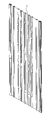
- FIG. 1 is a horizontal section view of the interior reinforcing material
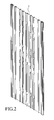
- FIG. 2 is a perspective drawing of the reinforcing material
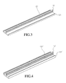
- FIG. 3 is a perspective drawing of a first embodiment of left and right stiles (type 1 );
- FIG. 4 is a perspective drawing of a second embodiment of left and right stiles (type 2);
- FIGS. 5A and 5B show the first embodiment left and right stiles (type 1), door panel, and interior reinforced material before and after assembly;
- FIGS. 6A and 6B show the second embodiment left and right stiles (type 2), door panel and interior reinforced material before and after assembly;
- FIG. 7 shows a first embodiment of the door assembly drawing (type A) with matching door panels
- FIG. 8 shows a second embodiment of the door assembly drawing (type B) with matching door panels
- FIG. 9 shows a third embodiment of the door assembly drawing (type C) with matching door panels
- FIG. 10 is an exploded view of the door assembly shown in FIG. 8;
- FIG. 11 is an assembly view of a polyurethane-filled door
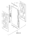
- FIG. 12 is an exploded view of the door as shown in FIG. 11;
- FIGS. 13 A- 13 D show the left and right stiles, door panels, and left and right reinforcing materials for a polyurethane-filled door before and after the stiles are inserted into the reinforcing materials.
- FIG. 1 is a section view of an extruded plastic interior reinforcing material wherein the material used is PVC (polyvinyl chloride) having two concave areas or grooves 13 of 2.2 mm width and 4.5 mm depth on each of two sides thereof.
- the grooves are inserted with the ribs 121 , 121 ′ (in FIGS. 5 , 6 ) on two sides of a door panel (FIGS. 7, 8, 9 ).
- the right and left stiles 5 , 5 ′ are fitted into grooves 13 with a flexible-rigid co-extrusion convex part or tongue 12 , 12 ′ (as shown in FIGS. 3, 4).
- FIG. 2 is a perspective view of an extruded plastic interior reinforcement material 7 having an opening of 80 mm width and 400 mm length cut in its side for receiving a handle 10 (as shown in FIGS. 7, 8, 9 ).
- the hollow reinforcement convex structure 18 can be matched with various types of door panels 71 , 81 , 91 (FIGS. 7, 8, 9 ).
- FIG. 3 is a perspective view of a first embodiment (type 1) of the left and right stiles 5 , wherein a middle part of the stile's “T”-shaped appearance includes a tongue 12 having a lip 121 on both sides thereof that will be tightly glued to the door panel 71 , 81 , 91 (FIGS. 7, 8, 9 ) and interior reinforcement material (FIGS. 7, 8, 9 ) so as to form a stile structure of 6 mm width.
- FIG. 4 is the perspective view of a second embodiment of left and right stiles 5 ′ (type 2), wherein the middle part of the stile's “T” shaped appearance is a tongue 12 ′ having a lip 121 ′ at both sides thereof that will be tightly glued to the door panel 71 , 81 , 91 (FIGS. 7, 8, 9 ) and the interior material 10 (FIGS. 7, 8, 9 ), so as to form a stile structure of 10 mm width.
- FIG. 5A is a cross-sectional view (type 1 styles) before assembly of left and right stiles 5 showing their location with respect to the door panel 71 , 81 , 91 , ribs 17 , and the interior reinforced material.
- the concave part 13 of the interior reinforced material is designed to be tightly glued with the tongue 12 of the left and right stiles 5 .
- FIG. 5B shows the relative positions of the door panels 71 , 81 , 91 , and the interior reinforced material 7 after assembly.
- FIG. 6A shows the relative positions of the door panel 71 , 81 , 91 having ribs 17 , the interior reinforced material 7 in the second embodiment of the left and right stiles 5 ′ before assembly.
- the concave part 13 of the interior reinforced material is designed to be tightly glued with the flexible-rigid co-extrusion convex part of the left and right stiles 5 ′.
- FIG. 6B shows the relative positions of the door panels 71 , 81 , 91 and the interior reinforced material 7 after assembly.
- FIG. 7 shows the relative positions of a first embodiment of a door assembly drawing (type A) matching with a door panel.
- the assembly steps for this embodiment are as follows:
- top and bottom structural members 8 , 9 could be wood, plastic injection moldings, or extrusion moldings.
- FIG. 8 shows the relative positions for a second embodiment of the door assembly (type B) being matched with another door panel.
- the assembly steps are as follows:
- top and bottom structural members 8 , 9 could be wood, plastic injection moldings, or extrusion moldings.
- FIG. 9 shows the relative positions of a third embodiment of a door assembly (type C) being matched with another door panel.
- the assembly steps are as follows:
- top and bottom structural members 8 , 9 could be wood, plastic injection moldings, or extrusion moldings.
- FIG. 10 is an exploded isometric view of the door construction of FIGS. 7 - 9 .
- the extruded plastic interior reinforced material 7 acts as the primary body structure of the door.
- the door is covered with door panels 71 , 81 , 91 having ribs on two sides thereof.
- Reference numerals 5 , 5 ′ are T-shaped portions of the left and right stiles.
- Reference numerals 8 , 9 are top and bottom structural members which create a closed space with the left and right stiles 5 , 5 ′.
- FIG. 11 is an assembly drawing showing the filling of polyurethane into the door. The steps are as follows:
- FIG. 12 is an exploded isometric drawing of the door filled with polyurethane.
- the handle reinforcement 10 is a rectangular solid that is covered with door panels 71 , 81 and 91 .
- the T-shaped portions of the left and right stiles 5 , 5 ′, and the top and bottom structural members 8 , 9 form a closed space.
- FIGS. 13 A- 13 D show the relative positions among the various embodiments with filled polyurethane 15 filling.
- the left and right reinforced structural members 14 has a 3.6 mm width and a 12 mm depth.
- the door panels 71 , 81 , 91 have ribs on both sides thereof, and the left and right stiles 5 , 5 ′ have a tongue 12 , 12 ′.
- FIGS. 13 A- 13 D includes:
- the extruded plastic interior material 7 supports door panels 71 , 81 , 91 having ribs on both sides that are glued and fixed together with each other.
- the reinforcing material is rigid PVC, there are convex hollow structures appropriately spaced in support of door panels. This single molded structure can reinforce the door strength, facilitate the assembling process, reduce product defects, and reduce inefficiencies caused by the reinforced materials being scattered and assembled individually, thus causing a waste of time and cost, and lack of strength.
- the left and right stiles 5 , 5 ′ are made of PVC using co-extrusion techniques during which the tongues 12 , 12 ′ are inserted in the grooves 13 of the left and right structural members 14 to create a strong construction without gluing. Further, the rigid PVC is easy to modify and therefore can be used to meet special requirements for the door or frame by changing dimensions to prevent the defects caused by overflowing glue in conventional structures and difficult partial modification.
- the door panels 71 , 81 , 91 each have curved end portions 101 , and each of the left and right structural members 14 including a pair of recessed 20 portions 141 that receive a respective one of the curved end portions 101 of the door panels 71 , 81 , 91 , as shown in FIGS. 13A and 13C.
- the curved end portions 101 are substantially perpendicular to the tongues 12 , 12 ′ of the T-shaped left and right stiles 5 , 5 ′.
- the left and right reinforced structural members 14 have groove shapes that are joined together with the convex parts of the left and right stiles 5 , 5 ′. They are then matched with the top and bottom stiles and two door panels to form a closed space. After that, a hole is drilled in the bottom stile for filling the inner part with polyurethane and forming an imitation wood texture door.
- This invention can be made with different dimensions of door width as required.
- the manufacturing method uses an extruded plastic interior reinforced material 7 with top and bottom structural members and two door panels forming a closed space.
- the door may be cut to the require width after gluing together.
- a groove is then cut on both sides to receive left and right stiles that are inserted in the reinforcing structure and fitted with an imitation wood grain door.
- the extruded plastic interior reinforcing material can be replaced by polyurethane filling to increase the flexibility and provide for multiple patterns.
- the raw material of door can be either thermosets or thermoplastics.
- an FRP (fiber reinforced plastic) additive is not required.
- the door can also be recycled for other purposes to fulfill the requirement of environmental protection.
- Al (OH) 3 By adding Al (OH) 3 during the compounding, it can be fireproofed for safety. If this door replaces a wooden door, it can reduce wood consumption in a large amount, and thus protect the precious resource of forests.
- this creation can save many manufacturing steps, simplify assembling procedures, and reduce manpower cost.
- This door structure is also easily cuttable and moisture-proof to prevent door bending. Therefore, the inventive door is useful, economic and creative, and can promote product quality, and as a result, is novel and non-obvious.
Landscapes
- Engineering & Computer Science (AREA)
- Civil Engineering (AREA)
- Structural Engineering (AREA)
- Securing Of Glass Panes Or The Like (AREA)
Abstract
A press-molded door including a reinforcing structure having a plurality of hollow vertical stiffeners joined by a horizontal web, two of the stiffeners arranged on opposite edges of the reinforcing structure with a groove formed in an edge face thereof, a T-shaped stile arranged in each edge stiffener with a tongue that fits into the groove, and front and back panels arranged on opposite sides of the reinforcing structure.
Description
- This application is a division of non-provisional application Ser. No. 09/390,774 filed Sep. 7, 1999.
- 1. Field of the Invention
- This invention relates to a stile structure and interior reinforcement for a press molded door, and, more particularly, to a press molded door with an improved reinforcing material and stile structure.
- 2. Description of the Related Art
- Taiwan Utility Model application No. 84204994, entitled “An Improvement For The Assembly Structure Of Pressed-Molded Door”, was applied for and granted prior to this invention. However, the subject matter of that patent suffers from drawbacks in connection with the gluing process, material used, assembly time, and size flexibility. This invention is intended to solve those problems and improve the ease of assembly.
- This invention relates to a press molded door with an improved reinforcing and stile structure comprising two door panels, top, bottom, left and right structural members, and an interior reinforced material. The invention is characterized by the structure of the co-extruded, interior reinforcement which is rigid in one plane and flexible in another plane. The above mentioned interior reinforcement is made with the door panel, together, by a single mold that can reduce the assembly time, enhance the strength of door, and enhance the quality. The above mentioned reinforcement is recessed near the handle to form a closed space with two top and bottom structural members. Finally, an imitation wood grain finish is added to the door.
- The above mentioned left and right structural members of this press molded door have a groove into which T-shaped left and right stiles are inserted via a compression-fit. The top and bottom structural members are combined with the two door panels to form a closed space. After that, a hole is drilled in the bottom structural member for filling the inside with polyurethane to make an imitation wood grain door.
- Moreover, the press-molded door of this invention can be made to different widths according to customers' needs, by cutting two sides of the door. Furthermore, doors with various widths can be produced by arranging the left and right stiles at different widths.
- The following are illustrative drawing examples of the invention.
- FIG. 1 is a horizontal section view of the interior reinforcing material;
- FIG. 2 is a perspective drawing of the reinforcing material;
- FIG. 3 is a perspective drawing of a first embodiment of left and right stiles (type 1 );
- FIG. 4 is a perspective drawing of a second embodiment of left and right stiles (type 2);
- FIGS. 5A and 5B show the first embodiment left and right stiles (type 1), door panel, and interior reinforced material before and after assembly;
- FIGS. 6A and 6B show the second embodiment left and right stiles (type 2), door panel and interior reinforced material before and after assembly;
- FIG. 7 shows a first embodiment of the door assembly drawing (type A) with matching door panels;
- FIG. 8 shows a second embodiment of the door assembly drawing (type B) with matching door panels;
- FIG. 9 shows a third embodiment of the door assembly drawing (type C) with matching door panels;
- FIG. 10 is an exploded view of the door assembly shown in FIG. 8;
- FIG. 11 is an assembly view of a polyurethane-filled door;
- FIG. 12 is an exploded view of the door as shown in FIG. 11; and
- FIGS. 13A-13D show the left and right stiles, door panels, and left and right reinforcing materials for a polyurethane-filled door before and after the stiles are inserted into the reinforcing materials.
- FIG. 1 is a section view of an extruded plastic interior reinforcing material wherein the material used is PVC (polyvinyl chloride) having two concave areas or
grooves 13 of 2.2 mm width and 4.5 mm depth on each of two sides thereof. The grooves are inserted with theribs left stiles grooves 13 with a flexible-rigid co-extrusion convex part ortongue stiffener 18 of reinforcing material to support thedoor panel - FIG. 2 is a perspective view of an extruded plastic
interior reinforcement material 7 having an opening of 80 mm width and 400 mm length cut in its side for receiving a handle 10 (as shown in FIGS. 7, 8, 9). The hollowreinforcement convex structure 18 can be matched with various types ofdoor panels - FIG. 3 is a perspective view of a first embodiment (type 1) of the left and
right stiles 5, wherein a middle part of the stile's “T”-shaped appearance includes atongue 12 having alip 121 on both sides thereof that will be tightly glued to thedoor panel - FIG. 4 is the perspective view of a second embodiment of left and
right stiles 5′ (type 2), wherein the middle part of the stile's “T” shaped appearance is atongue 12′ having alip 121′ at both sides thereof that will be tightly glued to thedoor panel - FIG. 5A is a cross-sectional view (type 1 styles) before assembly of left and
right stiles 5 showing their location with respect to thedoor panel ribs 17, and the interior reinforced material. Theconcave part 13 of the interior reinforced material is designed to be tightly glued with thetongue 12 of the left andright stiles 5. FIG. 5B shows the relative positions of thedoor panels material 7 after assembly. - FIG. 6A shows the relative positions of the
door panel ribs 17, the interior reinforcedmaterial 7 in the second embodiment of the left andright stiles 5′ before assembly. Theconcave part 13 of the interior reinforced material is designed to be tightly glued with the flexible-rigid co-extrusion convex part of the left andright stiles 5′. FIG. 6B shows the relative positions of thedoor panels material 7 after assembly. - FIG. 7 shows the relative positions of a first embodiment of a door assembly drawing (type A) matching with a door panel. The assembly steps for this embodiment are as follows:
- (1) Assemble the interior of
door panel 71 having ribs 17 (FIGS. 5, 6); - (2) Apply glue to every connected area;
- (3) Put the interior reinforced
material 7, handlereinforcement 10 and the top and bottomstructural members - (4) Apply glue to the required areas of another door panel;
- (5) Affix the left and right stiles inside two
door panels - (6) Wait for the glue to dry and finish the assembling steps.
- The top and bottom
structural members - FIG. 8 shows the relative positions for a second embodiment of the door assembly (type B) being matched with another door panel. The assembly steps are as follows:
- (1) Assemble the interior of
door panel 81 having ribs 17 (FIGS. 5, 6) on two sides; - (2) Apply glue to every connected area;
- (3) Put the interior reinforced
material 7, handlereinforcement 10, and the top and bottomstructural members - (4) Apply glue to the required areas of another door panel;
- (5) Affix the left and
right stiles door panels - (6) Wait for the glue to dry and finish the assembling process.
- The top and bottom
structural members - FIG. 9 shows the relative positions of a third embodiment of a door assembly (type C) being matched with another door panel. The assembly steps are as follows:
- (1) Assemble the interior of
door panel 81 having ribs 17 (FIGS. 5, 6) on two sides; - (2) Apply glue to every connected area;
- (3) Put the interior reinforced
material 7, handlereinforcement 10, and the top and bottomstructural members - (4) Apply glue to the required areas of another door panel;
- (5) Affix the left and
right stiles door panels - (6) Wait for the glue to dry and finish the assembling process.
- The top and bottom
structural members - FIG. 10 is an exploded isometric view of the door construction of FIGS. 7-9. In this embodiment, the extruded plastic interior reinforced
material 7 acts as the primary body structure of the door. The door is covered withdoor panels Reference numerals Reference numerals right stiles - FIG. 11 is an assembly drawing showing the filling of polyurethane into the door. The steps are as follows:
- (1) Assemble the interior of
door panel - (2) Apply glue to every connected area;
- (3) Put the left and right reinforced
structural members 14 having groove shape at sides, handlereinforcement 10 and the top and bottomstructural members - (4) Apply glue to the required areas of another door panel;
- (5) Affix the left and
right stiles door panels - (6) Wait for the glue to dry and finish the assembling process;
- (7) Drill a hole in the bottom stile and fill the door with polyurethane.
- FIG. 12 is an exploded isometric drawing of the door filled with polyurethane. The
polyurethane 15, and the left and right reinforcedstructural members 14 having a groove shape on each side thereof, constitute the primary body structure of the door. Thehandle reinforcement 10 is a rectangular solid that is covered withdoor panels right stiles structural members - FIGS. 13A-13D show the relative positions among the various embodiments with filled
polyurethane 15 filling. The left and right reinforcedstructural members 14 has a 3.6 mm width and a 12 mm depth. Thedoor panels right stiles tongue - The embodiment illustrated in FIGS. 13A-13D includes:
- (1) two
door panels - (2) an extruded plastic interior reinforced
material 7; - (3) two extruded plastic left and
right stiles - (4) two top and bottom
structural members - (5) a
handle reinforcement 10. - The extruded plastic
interior material 7 supportsdoor panels - Since the reinforcing material is rigid PVC, there are convex hollow structures appropriately spaced in support of door panels. This single molded structure can reinforce the door strength, facilitate the assembling process, reduce product defects, and reduce inefficiencies caused by the reinforced materials being scattered and assembled individually, thus causing a waste of time and cost, and lack of strength.
- The left and
right stiles tongues grooves 13 of the left and rightstructural members 14 to create a strong construction without gluing. Further, the rigid PVC is easy to modify and therefore can be used to meet special requirements for the door or frame by changing dimensions to prevent the defects caused by overflowing glue in conventional structures and difficult partial modification. - The
door panels curved end portions 101, and each of the left and rightstructural members 14 including a pair of recessed 20portions 141 that receive a respective one of thecurved end portions 101 of thedoor panels curved end portions 101 are substantially perpendicular to thetongues right stiles - Another model of this invention is that the left and right reinforced
structural members 14 have groove shapes that are joined together with the convex parts of the left andright stiles - This invention can be made with different dimensions of door width as required. The manufacturing method uses an extruded plastic interior reinforced
material 7 with top and bottom structural members and two door panels forming a closed space. The door may be cut to the require width after gluing together. A groove is then cut on both sides to receive left and right stiles that are inserted in the reinforcing structure and fitted with an imitation wood grain door. - For the preceding method, the extruded plastic interior reinforcing material can be replaced by polyurethane filling to increase the flexibility and provide for multiple patterns.
- Generally, the raw material of door can be either thermosets or thermoplastics. During the manufacturing process with thermosets, an FRP (fiber reinforced plastic) additive is not required. The door can also be recycled for other purposes to fulfill the requirement of environmental protection. By adding Al (OH) 3 during the compounding, it can be fireproofed for safety. If this door replaces a wooden door, it can reduce wood consumption in a large amount, and thus protect the precious resource of forests.
- In summary, this creation can save many manufacturing steps, simplify assembling procedures, and reduce manpower cost. This door structure is also easily cuttable and moisture-proof to prevent door bending. Therefore, the inventive door is useful, economic and creative, and can promote product quality, and as a result, is novel and non-obvious.
- Although preferred embodiments have been disclosed, other embodiments and modifications of the invention are intended to be covered by the spirit and scope of the appended claims.
Claims (13)
1. A press-molded door comprising:
a reinforcing structure that is flexible about a vertical axis and substantially rigid about a horizontal axis;
front and back panels arranged on opposite sides of the reinforcing structure; and
at least one stile arranged on an edge of the reinforcing structure.
2. The press-molded door recited in claim 1 wherein said reinforcing structure and door panels are simultaneously pressed in the same mold.
3. The press-molded door recited in claim 1 wherein said reinforcing structure includes a plurality of convex hollow stiffeners extending vertically on a web.
4. The press-molded door recited in claim 1 , further comprising a handle reinforcement secured to a recess in the reinforcing structure.
5. The press-molded door recited in claim 4 wherein said handle reinforcement includes a rectangular solid material.
6. The press-molded door recited in claim 3 wherein one of said stiffeners is an edge stiffener arranged on the edge of the reinforcing structure and includes a groove for receiving a tongue extending from the stile.
7. The press-molded door recited in claim 6 wherein the stile is T-shaped with a top lip formed at each edge of a cap of the T.
8. The press-molded door recited in claim 7 wherein at least one of the front and back panels includes an edge lip arranged between the side stiffener and the top lip of the T-shaped stile.
9. The press-molded door recited in claim 1 further comprising additional stiles for enclosing all edges of the reinforcing structure.
10. A press-molded door, comprising:
a reinforcing structure having a plurality of hollow vertical stiffeners joined by a horizontal web;
two of the stiffeners arranged on opposite edges of the reinforcing structure;
each of the two edge stiffeners having a groove formed in an edge face thereof;
a T-shaped stile arranged in each edge stiffener, each stile having a tongue that fits into the groove; and
front and back panels arranged on opposite sides of the reinforcing structure.
11. The press-molded door recited in claim 10 wherein each panel includes an edge lip that extends under the stile when the tongue is positioned in the groove.
12. The press-molded door recited in claim 11 wherein each of the stiles includes a top lip on each edge of a top of the t-shaped stile, said top lips engaging corresponding edge lips on the panels.
13. The press-molded door recited in claim 11 wherein said reinforcing 25 structure and door panels are simultaneously pressed in the same mold.
Priority Applications (1)
| Application Number | Priority Date | Filing Date | Title |
|---|---|---|---|
| US10/217,453 US20020184849A1 (en) | 1999-09-07 | 2002-08-14 | Press molded door with improved reinforcement material and stile structure |
Applications Claiming Priority (2)
| Application Number | Priority Date | Filing Date | Title |
|---|---|---|---|
| US09/390,774 US6453638B2 (en) | 1999-09-07 | 1999-09-07 | Press molded door with improved reinforcement material and stile structure |
| US10/217,453 US20020184849A1 (en) | 1999-09-07 | 2002-08-14 | Press molded door with improved reinforcement material and stile structure |
Related Parent Applications (1)
| Application Number | Title | Priority Date | Filing Date |
|---|---|---|---|
| US09/390,774 Division US6453638B2 (en) | 1999-09-07 | 1999-09-07 | Press molded door with improved reinforcement material and stile structure |
Publications (1)
| Publication Number | Publication Date |
|---|---|
| US20020184849A1 true US20020184849A1 (en) | 2002-12-12 |
Family
ID=23543880
Family Applications (2)
| Application Number | Title | Priority Date | Filing Date |
|---|---|---|---|
| US09/390,774 Expired - Fee Related US6453638B2 (en) | 1999-09-07 | 1999-09-07 | Press molded door with improved reinforcement material and stile structure |
| US10/217,453 Abandoned US20020184849A1 (en) | 1999-09-07 | 2002-08-14 | Press molded door with improved reinforcement material and stile structure |
Family Applications Before (1)
| Application Number | Title | Priority Date | Filing Date |
|---|---|---|---|
| US09/390,774 Expired - Fee Related US6453638B2 (en) | 1999-09-07 | 1999-09-07 | Press molded door with improved reinforcement material and stile structure |
Country Status (1)
| Country | Link |
|---|---|
| US (2) | US6453638B2 (en) |
Cited By (3)
| Publication number | Priority date | Publication date | Assignee | Title |
|---|---|---|---|---|
| US20040035070A1 (en) * | 2002-06-21 | 2004-02-26 | Chen Kuei Yung Wang | Economical impact resistant compression molded door |
| US20060070347A1 (en) * | 2004-09-23 | 2006-04-06 | Manish Gupta | Impact resistant door facing, method of forming impact resistant door facing, and door formed therewith |
| US7721500B2 (en) | 2002-10-31 | 2010-05-25 | Jeld-Wen, Inc. | Multi-layered fire door and method for making the same |
Families Citing this family (20)
| Publication number | Priority date | Publication date | Assignee | Title |
|---|---|---|---|---|
| IT1315444B1 (en) * | 2000-05-11 | 2003-02-10 | Sydel Srl | PANEL STRUCTURE PARTICULARLY FOR THE CONSTRUCTION OF RAISED FLOORS. |
| DE10047774C1 (en) * | 2000-09-27 | 2002-08-08 | Rittal Gmbh & Co Kg | Door for housing for electrical component has vertical frame profiles in form of grooves in which cladding panels are held by edges, cross-struts with end fittings for fixing in profiles |
| US6945006B2 (en) * | 2001-03-09 | 2005-09-20 | American Marble Industries | Countertop assembly and method of manufacture thereof |
| CA2383457A1 (en) * | 2002-04-25 | 2003-10-25 | Royal Group Technologies Limited | Modular garage door |
| US6871464B2 (en) * | 2003-04-09 | 2005-03-29 | Liu Hui Hung | Door structure for preventing water leakage |
| US7621102B2 (en) * | 2003-10-14 | 2009-11-24 | E.M.E.H., Inc. | Door edge construction |
| US7886501B2 (en) * | 2003-10-14 | 2011-02-15 | Construction Specialties, Inc. | Door edge construction |
| US7228667B2 (en) * | 2003-12-19 | 2007-06-12 | Tuff Shed, Inc. | Door system for a building |
| CA2507205A1 (en) * | 2005-05-13 | 2006-11-13 | Gomes, Helder | Frameless garage door panel section and garage door assembly incorporating same |
| US7886500B2 (en) * | 2005-05-27 | 2011-02-15 | Maytag Corporation | Refrigerator door with ratcheting end cap |
| JP4531671B2 (en) * | 2005-10-12 | 2010-08-25 | 株式会社神戸製鋼所 | Hollow panel and manufacturing method thereof |
| AT9351U3 (en) * | 2007-05-03 | 2011-02-15 | Reinex Tueren Gmbh | FULL PLASTIC DOOR |
| NL1034054C2 (en) * | 2007-06-28 | 2008-12-30 | Aerocat B V | Trolley. |
| DE202007014991U1 (en) * | 2007-10-27 | 2009-03-12 | Rehau Ag + Co | Edging strip for furniture |
| US8341920B2 (en) * | 2008-08-01 | 2013-01-01 | Everlast Doors Industries, Sa | Metal door |
| JP4688234B1 (en) * | 2010-03-16 | 2011-05-25 | 株式会社 構造材料研究会 | Rectangular metal plate square tube reinforcement structure |
| HK1203284A2 (en) * | 2014-01-20 | 2015-10-16 | 黄龙辉 | Forced entry resistance system for wooden doors |
| CN105064879A (en) * | 2015-09-18 | 2015-11-18 | 安徽安旺门业有限公司 | Hollow solid wood door |
| US10711513B2 (en) * | 2018-01-05 | 2020-07-14 | Nan Ya Plastics Corporation | Door panel and a stile thereof |
| CA3137121A1 (en) | 2019-06-04 | 2020-12-10 | Plastpro 2000, Inc. | Door comprising vented stile, and method of making the same |
Family Cites Families (10)
| Publication number | Priority date | Publication date | Assignee | Title |
|---|---|---|---|---|
| GB553015A (en) * | 1941-02-03 | 1943-05-04 | Bengt Valter Karlson | Improvements in or relating to doors and similar constructions and to methods for the manufacture thereof |
| US2705820A (en) * | 1951-05-07 | 1955-04-12 | Colotrym Company | Molding strip |
| US3339329A (en) * | 1965-05-18 | 1967-09-05 | Edward T Berg | Arrangement for securing panels to the surface of a roof or wall |
| US3786609A (en) * | 1972-01-07 | 1974-01-22 | Acorn Prod Co | Cored insulated door |
| US3837134A (en) * | 1973-07-11 | 1974-09-24 | Acorn Building Components Inc | Sheet metal faced slab door |
| US4386482A (en) * | 1980-10-09 | 1983-06-07 | Walled Lake Door Co. | Wood door with molding strips forming annular seal around the periphery of the door to prevent delamination |
| DE3202918C2 (en) * | 1982-01-29 | 1986-03-13 | Dynamit Nobel Ag, 5210 Troisdorf | Profile strip |
| US4748780A (en) * | 1984-01-28 | 1988-06-07 | Duropal-Werk Eberh. Wrede Gmbh & Co. Kg | Composite panels and methods of making composite panels |
| US5537789A (en) * | 1994-07-14 | 1996-07-23 | Therma-Tru Corp. | Compression molded door assembly |
| US5875609A (en) * | 1997-05-12 | 1999-03-02 | Quinif; Edward G. | Expandable spacer cores for panel doors and the method of making same |
-
1999
- 1999-09-07 US US09/390,774 patent/US6453638B2/en not_active Expired - Fee Related
-
2002
- 2002-08-14 US US10/217,453 patent/US20020184849A1/en not_active Abandoned
Cited By (4)
| Publication number | Priority date | Publication date | Assignee | Title |
|---|---|---|---|---|
| US20040035070A1 (en) * | 2002-06-21 | 2004-02-26 | Chen Kuei Yung Wang | Economical impact resistant compression molded door |
| US7721500B2 (en) | 2002-10-31 | 2010-05-25 | Jeld-Wen, Inc. | Multi-layered fire door and method for making the same |
| US20060070347A1 (en) * | 2004-09-23 | 2006-04-06 | Manish Gupta | Impact resistant door facing, method of forming impact resistant door facing, and door formed therewith |
| US9884438B2 (en) | 2004-09-23 | 2018-02-06 | Masonite Corporation | Impact resistant door facing, method of forming impact resistant door facing, and door formed therewith |
Also Published As
| Publication number | Publication date |
|---|---|
| US6453638B2 (en) | 2002-09-24 |
| US20010045080A1 (en) | 2001-11-29 |
Similar Documents
| Publication | Publication Date | Title |
|---|---|---|
| US6453638B2 (en) | Press molded door with improved reinforcement material and stile structure | |
| US6665997B2 (en) | Edge inserts for stiles of molded doors | |
| US5644870A (en) | Compression molded door assembly | |
| US6619005B1 (en) | Molded doors with large glass insert | |
| US5887398A (en) | Synthetic door casement structure for patio doors and like, and method | |
| US5167105A (en) | Hollow door construction using an improved void filler | |
| US6729095B2 (en) | Refined assembly structure of hubbed door leaf installed with glass | |
| US5293726A (en) | Hollow composite interior door assembly | |
| CA2817433C (en) | Door jamb member, door jamb assembly incorporating same and kit therefor | |
| US3299595A (en) | Compound door | |
| EP1223289A2 (en) | Doors | |
| IE891883L (en) | Frame for doors and windows | |
| US20020091218A1 (en) | Thermoplastic door skins and method of manufacture thereof | |
| US3461629A (en) | Shutter structure | |
| EP0907000B1 (en) | A door slab assemble structure for the partly hollow door skin and glass | |
| EP1094192B1 (en) | Patio door with integral glazing frame | |
| KR200493451Y1 (en) | Door and window frame | |
| JP2010180694A (en) | Frame material and mounting structure of the same | |
| CN205743464U (en) | In the fan material of a kind of bar very | |
| GB2345512A (en) | Doors and door assemblies | |
| TWM517777U (en) | A retrofitted glass door fan without boring | |
| JP3150630B2 (en) | Construction materials | |
| JP3675928B2 (en) | Cover | |
| JPS6141911Y2 (en) | ||
| GB2292169A (en) | Closure member constructure |
Legal Events
| Date | Code | Title | Description |
|---|---|---|---|
| STCB | Information on status: application discontinuation |
Free format text: ABANDONED -- FAILURE TO RESPOND TO AN OFFICE ACTION |
|
| AS | Assignment |
Owner name: SILICON VALLEY BANK, CALIFORNIA Free format text: SECURITY INTEREST;ASSIGNOR:SOUNDHOUND, INC.;REEL/FRAME:055807/0539 Effective date: 20210331 |
|
| AS | Assignment |
Owner name: SOUNDHOUND, INC., CALIFORNIA Free format text: TERMINATION AND RELEASE OF SECURITY INTEREST IN PATENTS;ASSIGNOR:MONROE CAPITAL MANAGEMENT ADVISORS, LLC, AS COLLATERAL AGENT;REEL/FRAME:069480/0312 Effective date: 20241201 |