EP1094192B1 - Patio door with integral glazing frame - Google Patents
Patio door with integral glazing frame Download PDFInfo
- Publication number
- EP1094192B1 EP1094192B1 EP99121163A EP99121163A EP1094192B1 EP 1094192 B1 EP1094192 B1 EP 1094192B1 EP 99121163 A EP99121163 A EP 99121163A EP 99121163 A EP99121163 A EP 99121163A EP 1094192 B1 EP1094192 B1 EP 1094192B1
- Authority
- EP
- European Patent Office
- Prior art keywords
- frame
- skins
- door frame
- skin
- strip
- Prior art date
- Legal status (The legal status is an assumption and is not a legal conclusion. Google has not performed a legal analysis and makes no representation as to the accuracy of the status listed.)
- Expired - Lifetime
Links
Images


Classifications
-
- E—FIXED CONSTRUCTIONS
- E06—DOORS, WINDOWS, SHUTTERS, OR ROLLER BLINDS IN GENERAL; LADDERS
- E06B—FIXED OR MOVABLE CLOSURES FOR OPENINGS IN BUILDINGS, VEHICLES, FENCES OR LIKE ENCLOSURES IN GENERAL, e.g. DOORS, WINDOWS, BLINDS, GATES
- E06B3/00—Window sashes, door leaves, or like elements for closing wall or like openings; Layout of fixed or moving closures, e.g. windows in wall or like openings; Features of rigidly-mounted outer frames relating to the mounting of wing frames
- E06B3/70—Door leaves
- E06B3/72—Door leaves consisting of frame and panels, e.g. of raised panel type
- E06B3/725—Door leaves consisting of frame and panels, e.g. of raised panel type with separate hollow frames, e.g. foam-filled
-
- E—FIXED CONSTRUCTIONS
- E06—DOORS, WINDOWS, SHUTTERS, OR ROLLER BLINDS IN GENERAL; LADDERS
- E06B—FIXED OR MOVABLE CLOSURES FOR OPENINGS IN BUILDINGS, VEHICLES, FENCES OR LIKE ENCLOSURES IN GENERAL, e.g. DOORS, WINDOWS, BLINDS, GATES
- E06B3/00—Window sashes, door leaves, or like elements for closing wall or like openings; Layout of fixed or moving closures, e.g. windows in wall or like openings; Features of rigidly-mounted outer frames relating to the mounting of wing frames
- E06B3/54—Fixing of glass panes or like plates
- E06B3/58—Fixing of glass panes or like plates by means of borders, cleats, or the like
- E06B3/5892—Fixing of window panes in openings in door leaves
-
- E—FIXED CONSTRUCTIONS
- E06—DOORS, WINDOWS, SHUTTERS, OR ROLLER BLINDS IN GENERAL; LADDERS
- E06B—FIXED OR MOVABLE CLOSURES FOR OPENINGS IN BUILDINGS, VEHICLES, FENCES OR LIKE ENCLOSURES IN GENERAL, e.g. DOORS, WINDOWS, BLINDS, GATES
- E06B3/00—Window sashes, door leaves, or like elements for closing wall or like openings; Layout of fixed or moving closures, e.g. windows in wall or like openings; Features of rigidly-mounted outer frames relating to the mounting of wing frames
- E06B3/70—Door leaves
- E06B3/7015—Door leaves characterised by the filling between two external panels
- E06B2003/7023—Door leaves characterised by the filling between two external panels of foam type
-
- E—FIXED CONSTRUCTIONS
- E06—DOORS, WINDOWS, SHUTTERS, OR ROLLER BLINDS IN GENERAL; LADDERS
- E06B—FIXED OR MOVABLE CLOSURES FOR OPENINGS IN BUILDINGS, VEHICLES, FENCES OR LIKE ENCLOSURES IN GENERAL, e.g. DOORS, WINDOWS, BLINDS, GATES
- E06B3/00—Window sashes, door leaves, or like elements for closing wall or like openings; Layout of fixed or moving closures, e.g. windows in wall or like openings; Features of rigidly-mounted outer frames relating to the mounting of wing frames
- E06B3/70—Door leaves
- E06B2003/7059—Specific frame characteristics
- E06B2003/7082—Plastic frames
-
- E—FIXED CONSTRUCTIONS
- E06—DOORS, WINDOWS, SHUTTERS, OR ROLLER BLINDS IN GENERAL; LADDERS
- E06B—FIXED OR MOVABLE CLOSURES FOR OPENINGS IN BUILDINGS, VEHICLES, FENCES OR LIKE ENCLOSURES IN GENERAL, e.g. DOORS, WINDOWS, BLINDS, GATES
- E06B3/00—Window sashes, door leaves, or like elements for closing wall or like openings; Layout of fixed or moving closures, e.g. windows in wall or like openings; Features of rigidly-mounted outer frames relating to the mounting of wing frames
- E06B3/70—Door leaves
- E06B2003/7059—Specific frame characteristics
- E06B2003/7086—One-piece frames, e.g. made out of a single panel by cutting out a middle portion, moulded frames
Definitions
- US 5,644,870 discloses a door being formed from two rectangular compression molded skins, with each skin having inside surface and an outside surface and on its inside surface a plurality of projecting, parallel ribs along at least two of its edges, a hinge support having a plurality of grooves on its opposite sides with the grooves operable to interlock with the ribs on the skins along one side of the door when the skins are assembled with this support and an accessory support having a plurality of grooves on its opposite sides operable to interlock the ribs of the skins along the other side of the door when the skins are assembled therewith wherein no frame is required for the door when a foamed in place polyurethane core is formed between the skins.
- the door uses interlocking members at its side and top edges and a preformed bottom panel or insert.
- the sheets or skins employed to construct such doors are made by a sheet molding process wherein uncured resins, reinforced with fiber glass, are compressed between large molds, using pressure and heat, to form thin sheets or skins having a thickness from 0.05 inches to 0.120 inches. While the sheets formed by such process are strong, and can be embossed with wood graining on their outside surfaces, they remain quite flexible in the plane normal to their surfaces. For this reason, and others, to construct a door with these skins, it is often necessary that they be mounted on a rectangular stick frame by gluing them to the assembled frame and filling the resulting hollow space between the skins and the frame with a plastic foam, such as polyurethane foam which is foamed in place.
- a plastic foam such as polyurethane foam which is foamed in place.
- the thin skins when required to carry the weight of such glazing, can buckle under such loadings if the door frame constructed of these skins is not properly designed. Further, the glue used to bond the skins to the stick frame is placed under tremendous sheer loadings which can rip the skins from the frame if the design does not distribute the loading properly.
- an improved frame for supporting a large window light or pane in door frames constructed of synthetic materials and leaving an integral glazing frame for retaining the light or pane includes a first skin of a compression molded sheet material, the first skin having an aperture with a first integral edge strip oriented generally normal to the plane of the first skin and extending from and around such aperture, a second skin (and opposing skin) of a compression molded sheet material, the second skin having an aperture with a second integral edge strip oriented generally normal to the plane of the second skin and extending from and around such aperture, interlocking means formed on the edge strips operable to fixedly to join said edge strips of the two skins in a permanent overlapping relationship when glue is applied to the surfaces of the interlocking means, a glazing frame means associated with the edge strips having an integral extending flange projecting from one of the edge strips and a glazing strip operable to retain a window light between the flange and the glazing strip when said the edge strips are fixedly joined by the interlocking means,
- the upper portion 48 of the glazing strip 47 is designed to deflect slightly due to its reduced cross section (see Fig. 6) when its plug portion 51 is pushed into groove 46, forcing the angular tip 52 under lip 44 to lock the strip in place. Further its light or pane engaging face 53 is grooved to form two sealing faces 54 and 55.
- a vinyl or rubber seal strip 56 is shown associated with the pane engaging face of the strip in Fig. 6 and is employed to improve the seal against the light or pane 22 when it is retained by the glazing strip 47. If desired additional seal strips can be employed on this face, as illustrated in Figs. 2 and 3. This arrangement allows the glazing strip to be popped out of groove 46 to replace the light or pane, if necessary.
- the stile posts 32 and the rail members 33 and 38 may have additional features to enhance the strength of the door frame 21 or the utility of the resulting door frame.
- the stile posts 32 and the top rail member 33 they can be constructed of wood, metal and plastic extrusions. Normally the sides of these members which engage the inner surfaces of the skins have grooves 69 which allow any excess glue to flow into the grooves, forming a glue ridge in the groove that increases the shear strength between the skin and the stile posts and the top rail member.
- stile posts can include vertical stops 70 which the peripheral edges 61 of the skins 30 and 31 can abut against, as shown in Fig. 2.
Landscapes
- Engineering & Computer Science (AREA)
- Civil Engineering (AREA)
- Structural Engineering (AREA)
- Securing Of Glass Panes Or The Like (AREA)
Description
- Doors made of synthetic materials have become common place in the construction industry for both residential and commercial buildings. Such products are durable, stable and often include a wood graining on the surfaces to give these doors the appearance of natural wooden doors. Such characteristics are desirable to owners, builders and architects.
- EP-A-0 359 906 discloses a frame assembly for doors, windows and the like. In particular the assembly includes a frame defining an opening for receiving and retaining a central panel. The frame is formed of two joined skins, which may be molded in the same mold and which are provided with inwardly extending flanges having notched areas on opposite sides of the flanges such that the skins can be joined together to form a lap joint on the exterior edge and to seal a central panel in the opening. Foamable insulating material is provided as a core between the two skins with a separate sealant material provided to seal the central panel. Passage means are provided for introducing the sealant material and the insulating material.
- US 5,644,870 discloses a door being formed from two rectangular compression molded skins, with each skin having inside surface and an outside surface and on its inside surface a plurality of projecting, parallel ribs along at least two of its edges, a hinge support having a plurality of grooves on its opposite sides with the grooves operable to interlock with the ribs on the skins along one side of the door when the skins are assembled with this support and an accessory support having a plurality of grooves on its opposite sides operable to interlock the ribs of the skins along the other side of the door when the skins are assembled therewith wherein no frame is required for the door when a foamed in place polyurethane core is formed between the skins. The door uses interlocking members at its side and top edges and a preformed bottom panel or insert.
- US 5,887,398 discloses a synthetic door casement being composed of multiple panels of L-shaped compression molded skin panels which are joined with batten means on their inner surfaces to form a pair of opposed rectangular casement skins which casement skins are then joined on opposite sides of an outer frame surrounding an inner frame to form a hollow rectangular casement which is then filled with a plastic foam. The inner frame has an external recess to receive a glass pane along with cooperative retention moldings to hold the pane in place in the recess of the inner frame once the pane is inserted therein. As described with reference to figures 5 to 9, the L-shaped skin panels are assembled with an outer frame composed of a vertical stile, which is positioned to engage a bottom rail and a top rail. Furthermore, the site opposed this stile is a matching vertical stile. In order to obtain sufficient strength of the door casement the integral edges are essential.
- Popular synthetic door structures are those constructed of sheet molded resins reinforced with fiber glass, such as disclosed in U. S. Patent 5,644,870 issued to Chen describing the construction of one of these type of doors. In addition there a number of patents assigned to Therma-Tru Corporation which taught this same type of construction, e.g., see U. S. Letters Patent 4,550,540 issued to Thorn. The sheet molding compounds (SMCs) employed are molding resins which include unsaturated polyesters resinous compositions, such as those defined in U. S. Letters Patent Nos. 3,772,241 issued to Kroexel and U. S. Letters Patent No. 3,884,612 issued to Ivor Pratt et al, which are typically reinforced with fiberglass before molding. Such compositions are processed, by the well known sheet molding processes, into thin sheets or skins.
- Other patents describing the use of compression molded sheets in door structures, include U.S. Patent No. 4,901,493, U.S. Patent No. 4,860,512, U.S. Patent No. 4,864,789 and U.S. Pat. No. 4,965,030 all issued to Thorn, along with U.S. Patent No. 5,142,835 issued to Mrocca and U.S. Patent No. 5,075,059 issued to Croon.
- According to the reference patents, as well as other patents, the sheets or skins employed to construct such doors are made by a sheet molding process wherein uncured resins, reinforced with fiber glass, are compressed between large molds, using pressure and heat, to form thin sheets or skins having a thickness from 0.05 inches to 0.120 inches. While the sheets formed by such process are strong, and can be embossed with wood graining on their outside surfaces, they remain quite flexible in the plane normal to their surfaces. For this reason, and others, to construct a door with these skins, it is often necessary that they be mounted on a rectangular stick frame by gluing them to the assembled frame and filling the resulting hollow space between the skins and the frame with a plastic foam, such as polyurethane foam which is foamed in place. The frame and foam cooperate with the skins glued to the frame to increase the rigidity of the door structure normal to the plane of the surface of the skins. Moreover the skins provide more than adequate integrity to the plane of the surface of the skins for the lightweight door structures described in the prior art.
- While the designs described are satisfactory for doors without large lights (windows) and for doors with small lights, the described construction has been found less that satisfactory for doors with large lights, which are often referred to as patio doors, due to the heavy loadings induced on the frame from the weight of the glass of the tights.
- With today's environmental concerns, patio doors often have double glazing (two panes of glass separated by a small space filled with a gas) which requires a frame supporting such double glazing to carry very substantial loadings. In fact some building codes require such double glazing.
- It can be appreciated that the thin skins, when required to carry the weight of such glazing, can buckle under such loadings if the door frame constructed of these skins is not properly designed. Further, the glue used to bond the skins to the stick frame is placed under tremendous sheer loadings which can rip the skins from the frame if the design does not distribute the loading properly.
- It is an object of the present invention, among others, to design a door structure employing thin compression molded skins as a frame for patio doors, and like, which will accommodate the loadings involved and provide an extended service life for the door frame.
- Another object is to provide better weather integrity for patio doors which are constructed in door frames formed with thin skins of compression molded panels by making the area around the window light or pane completely water tight.
- Still another object of the invention is to provide a design for such a patio door which better distributes the loadings to the skins forming the exterior components of the door frame.
- Also it is an object to provide an integral flange in one of the skins making up the frame to support one face of the light or pane, along with a removable interlocking glazing strip, to lock the light or pane in the resulting door frame.
- The above objects and many oilier advantages can be obtained with an improved frame for supporting a large window light or pane in door frames constructed of synthetic materials and leaving an integral glazing frame for retaining the light or pane includes a first skin of a compression molded sheet material, the first skin having an aperture with a first integral edge strip oriented generally normal to the plane of the first skin and extending from and around such aperture, a second skin (and opposing skin) of a compression molded sheet material, the second skin having an aperture with a second integral edge strip oriented generally normal to the plane of the second skin and extending from and around such aperture, interlocking means formed on the edge strips operable to fixedly to join said edge strips of the two skins in a permanent overlapping relationship when glue is applied to the surfaces of the interlocking means, a glazing frame means associated with the edge strips having an integral extending flange projecting from one of the edge strips and a glazing strip operable to retain a window light between the flange and the glazing strip when said the edge strips are fixedly joined by the interlocking means, a perimeter frame means closing the space between the skins about their outer perimeter fixedly joined to the respective skins on opposite sides of the frame means and operable to form a hollow space between the frame means and the interior surfaces of the joined edge strips, and a formed in place foam core in said hollow space.
- The defined objects of this invention, along with other advantages can be accomplished by employing the structures illustrated in the following drawings, wherein:
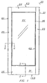
- Fig. 1 is a plan view of the novel patio door frame constructed according to the teachings of this invention;
- Fig. 2 is a cross section along lines 2-2 of Fig. 1 illustrating the integral edges of the skins which form a portion of the vertical glazing frame for holding a light or pane in the novel patio door frame structure;
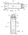
- Fig. 3 is a cross section along lines 3-3 of Fig. 1 illustrating the integral edges of the skins which form a portion of the horizontal glazing frame for holding a light or pane in the novel patio door frame structure;
- Fig. 4 is a broken away, exploded view of the portion of the vertical glazing frame illustrated in section in Fig. 2;
- Fig. 5 is an enlarged cross section of the joint formed between the respective integral edge strips of the skins employed to construct the novel door frame;
- Fig. 6 is an enlarged cross section of the glazing strip employed to retain a light or pane in the glazing frame.
- Fig. 7 is a plan view of the novel patio door frame structure illustrated in Fig. 1 before the second skin is assembled and the foam is incorporated m the structure, showing the interior components of the novel patio door frame structure;
- Fig. 8 is a perspective of an optional weather strip which can be attached to the bottom of the novel door frame, along with the bottom portion of the frame, with parts broken away, also shown in perspective; and
- Fig. 9 is a perspective of the bottom of the novel patio door showing optional roller assemblies that can be added to the door frame for sliding door applications for patio doors.
-
- The novel
patio door structure 20, shown in Fig. 1 includes two principal components, thedoor frame 21 and the window light orpane 22. The light or pane is typically formed of two glass sheets separated by small perimeter divider, with void between them preferably filled with a gas, and their edges sealed together to form a unit. Such units in a typically sized patio door (121,9 cm x 243,88 cm) ((4' x 8')) can weigh in the range of 45,36 kg (100 pounds). - As can be seen in Figs. 1, 2 and 3, when the light or
pane 22 is inserted into thedoor frame 21 and the entire weight of the pane is supported by the frame which includes compositevertical stiles 23 and a composite tophorizontal rail 24 along with a composite bottomhorizontal rail 25. In Fig. 2 the cross-section of the vertical stiles is illustrated with the similar cross section of the bottom horizontal rail illustrated in Fig. 3. - Referring to Figs. 2 and 3, it can be seen that the
skins vertical stile post 32 in Fig 2 andhorizontal rail member 38 in Fig. 3 at their outer peripheral edges. The top rail member is identical to the stile posts in cross section and therefore is not shown. The inner peripheral edges of these skins around thecentral aperture 26 include integral edges.Skin 30 has anintegral edge strip 34 incorporating an extending an upstanding flange 35 (with its axis oriented generally parallel to the surface of the associated skin) andskin 31 has anintegral edge strip 36 has with extendingrim 37. As described in U. S. Letters Patent No 5,644,870 integral edge strips similar to the of the type used in the current invention can be constructed with interlocking elements. A permanent joint between these strips can be effected with glue. Here theedge strips door frame 21 about the central aperture, as distinguished from the outer perimeter of the skins as shown in the '870 patent. These edge strips are designed to be interlocking structures as shown in Figs. 4 and 5. - The wall thickness of edge strips 34 and 36 is increased from the thickness of its associated skin (about 0,127 cm (0.05 inches) to 0,318 cm (0.12 inches)) to the range of 1,27 cm (0.5 inches).
Edge strip 34 has agroove 40 formed therein so that arib 41 at the distal end ofedge strip 36 will be received in this groove when the opposed skins are assembled providing an interlocking relationship. Typically these edge strips are joined with glue on their contiguous surfaces when interlocked with one another as shown in Fig. 5. - When the two
skins glazing frame 60, withrib 41 ofstrip 36 received in thegroove 40 ofstrip 34 and glue is applied to appropriate surfaces of the edge strips 34 and 36 before joining skins together. Such interlocking edge structures form a closed, hollow space between the skins and at the same time, double the wall thickness of the structure in the glazing frame to increases its strength. - Unique to
current door frame 21 is that theflange 35 and theapron 42 ofedge strip 34, having surfaces at right angles to one another, form part a theglazing frame 60 designed to receive the light orpane 22. In this regard the extending flange has a light orpane abutment face 43, typically grooved to enhance its sealing capacity against the light or pane. A light or pane inserted into the glazing frame abuts againstface 43. When this interface is effected the bottom edge of a light or pane is supported principally by the apron of edge strips of thebottom rail 25. Moreover, sinceedge strip 36 ofskin 31 underlays the apron (see Figs. 2, 3 and 5), increasing the thickness of the structure supporting the light or pane in the glazing frame, increased strength in this area is obtained which is where such strength is desired. A further advantage is achieved in that the skin, flange and apron are integral with one another, a single unit, resulting in a weather tight structure when the edge strips of the several skins are glued together in the described interlocking relationship. - Next since the compression molding process can achieve substantial detail,
edge strip 34 ofsheet 30 can include alip 44 at its distal end 45 formed during the compression molding process (see Fig. 5); however this lip, requiring some precession, can also be machined at the distal end of this edge if necessary. Whenedge strip 36 is joined with edge strip 34 agroove 46 is formed between the distal end 45 ofedge strip 34 and the extendingrun 37 ofedge strip 36, as illustrated in Fig. 5, showing the resulting joint in greater detail. - Referring to Figs. 2 and 3 it can be appreciated an
extruded glazing strip 47 having a profile as illustrated in Fig. 4 and Fig. 6 can be employed in thegroove 46 to retain a light orpane 22 12 previously inserted into thedoor frame 21. In this regard the glazing strip has anupper section 48 that is generally triangular in cross section, a cross section (best shown in Fig. 5) which is similar in cross section to the cross section to theintegral flange 35 ofedge strip 34, and, as can be seen in Figs 2 and 3, when glazing strip is assembled in the groove the exterior appearances of the glazing strip and the flange on opposite sides of the light or pane appear similar. In Fig. 6 it can be seen, thebottom section 49 of the glazing strip is designed to be received in thegroove 46 and includes ashoulder 50 which abuts on the top of the extendingrim 37 ofedge strip 36 to stabilize glazing strip and plugportion 51 which is actually received in thegroove 46. This plug portion terminates in anangular tip 52 which, when the plug portion is received in the groove, extends under thelip 44 at the distal end 45 ofedge strip 34 to lock the glazing strip in the groove. - The
upper portion 48 of theglazing strip 47 is designed to deflect slightly due to its reduced cross section (see Fig. 6) when itsplug portion 51 is pushed intogroove 46, forcing theangular tip 52 underlip 44 to lock the strip in place. Further its light orpane engaging face 53 is grooved to form two sealing faces 54 and 55. A vinyl orrubber seal strip 56 is shown associated with the pane engaging face of the strip in Fig. 6 and is employed to improve the seal against the light orpane 22 when it is retained by theglazing strip 47. If desired additional seal strips can be employed on this face, as illustrated in Figs. 2 and 3. This arrangement allows the glazing strip to be popped out ofgroove 46 to replace the light or pane, if necessary. - It can be appreciated from the forgoing description that glazing frame 60 (a frame for receiving a window light or pane) is formed by the described edge strips which is completely water tight and strong enough to support the heavy dual glass panes now in use. Further since the edge strips 34 and 36 are formed integrally with
skins pane 22 on theapron 42 on the bottom glazing frame is distributed uniformly to the skins forming the exterior surfaces ofdoor frame 21. - Once the
skins peripheral edges 61 of the skins are joined at their perimeter to the stile posts 32 by gluing the skins to these posts with the top peripheral edges 62 of the skins joined to thetop rail member 33, also with glue. Likewise the bottomperipheral edges 63 of the skins are joined with thebottom rail member 38 in the same manner (see Fig. 7). When this procedure is completed stile posts and rail members form a perimeter frame closing the outer edges of thedoor frame 21 leaving ahollow space 64 between the interior of theglazing frame 60 and the interior surfaces of these members. - In Fig. 7 the interior structure of the
door frame 21 can be seen beforeskin 31 is assembled withskin 30, illustrating the positions of the stile posts 32 and rails 33 and 38. If desired,filler members 65 can be glued to the central portion of the stile posts (as illustrated in Fig. 7) and to the skins to provide support for door hardware or accessories, such as latching mechanisms and locks (not shown). - Again referring to Fig. 7, once
skin 31 is assembled with the structure illustrated therein, the door frame is not yet complete. The final step is to introduce a plastic foam, such as polyurethane foam, into the resultinghollow space 64. This can be accomplished by drilling a small hole in thetop rail 33 member and injecting foaming agents into this hollow space to create afoam core 66. Polyurethane 15 compositions have the advantage that they can be foamed by CFC-free materials and produce gases which do not harm the Ozone layer. Moreover, halogen-free materials are also better flame retardant, making polyurethane foams the foam of choice for thecurrent door frame 21. Also polyurethane foams have better insulating qualities and better acoustical absorption characteristics, plus a history a satisfactory performance in such structures. When the foam agents are introduced into the hollow space in the frame, the resultingfoam core 66 fills the entire space, bonding to the skins, the stile posts and the rails, marrying these parts together as a composite unit. - While it is preferred that the
skins door frame 21 constructed with such composite skins. When such composite skins are employed, it may be desirable, in larger frames, to employ an inner rectangular frame or additional stiles of wood or steel which abut 16 against interior surfaces of theglazing frame 60 to increase its strength. Of course, it is an option to use such additional reinforcement adjacent to the interior of the glazing frame, even when single panel skins are employed. - The stile posts 32 and the
rail members door frame 21 or the utility of the resulting door frame. In the regard the stile posts 32 and thetop rail member 33, they can be constructed of wood, metal and plastic extrusions. Normally the sides of these members which engage the inner surfaces of the skins havegrooves 69 which allow any excess glue to flow into the grooves, forming a glue ridge in the groove that increases the shear strength between the skin and the stile posts and the top rail member. In addition stile posts can includevertical stops 70 which theperipheral edges 61 of theskins extensions 71 which extend beyond thestops 70 allowing a carpenter to trim top and side edges of thedoor frame 21 to fit into a door opening. - The
bottom rail member 38, while constructed of the same materials as the stile posts 32, is somewhat different in that it is often required to perform additional functions and is subject to extensive trimming to accommodate differences in the opening in which the door frame is installed. In this regard, as shown in Fig. 3, this rail member is usually equipped with two large, spaced apart grooves 72 which are quite deep. As a result even after extensive trimming, the grooves are still available to receive a bottom weather strip 73 shown in Fig. 8. Typically the weather strips has ribs that can be pushed into the grooves to retain it in place across the bottom of the door frame. - In addition the
bottom rail member 38 can be routed from the bottom to remove, in part, the portion 74 of tins this member between the grooves 72 so that recessed roller assemblies 75 can be inserted in the bottom of the door frame, as shown in Fig. 9. - In most cases the exterior surfaces of the
skins -
- 20
- patio door structure
- 21
- door frame
- 22
- light or pane
- 23
- vertical stile of
frame 21 - 24
- top horizontal rail of
frame 21 - 25
- bottom horizontal rail of
frame 21 - 26
- aperture
- 27
- ---
- 28
- ----
- 29 30
- skin
- 31
- skin
- 32
- stile post
- 33
- top rail member
- 34
- edge strip of
skin 30 - 35
- extending flange
- 36
- edge strip of
skin 31 - 37
- extending rim
- 38
- bottom rail member
- 39
- ----
- 40
- groove of
edge strip 34 - 41
- rib of
edge strip 36 - 42
- apron
- 43
- abutment face
- 44
- extending lip
- 45
- distal end of
edge strip 34 - 46
- groove
- 47
- glazing strip
- 48
- upper section of
stip 47 - 49
- lower section of
strip 47 - 50
- shoulder of
strip 47 - 51
- plug portion of
strip 47 - 52
- angular tip
- 53
- light or pane engaging face
- 54
- sealing face
- 55
- sealing face
- 56
- vinyl seal strip
- 57
- ----
- 58
- ----
- 59
- ----
- 60
- glazing frame
- 61
- vertical peripheral edges of skin
- 62
- top peripheral edges of the skins
- 63
- bottom peripheral edges of the skins
- 64
- hollow core
- 65
- filler members
- 66
- foam
- 67
- ----
- 68
- ----
- 69
- grooves in stiles posts
- 70
- stops
- 71
- extensions
- 72
- grooves
- 73
- portion between grooves 72
- 74
- weather strip
- 75
- rollers
Claims (11)
- Door frame (21) for supporting a large window light or pane (22) in doors constructed of synthetic materials having an integral glazing frame comprising:a first skin (30) of a compression molded sheet material, said first skin (30) having an aperture with a first integral edge strip (34) oriented generally normal to the surface plane of said first skin and extending from and around its aperture;a second skin (31) of a compression molded sheet material, said second skin having an aperture with a second integral edge strip (36) oriented generally normal to the surface plane of said second skin and extending from and around its aperture;interlocking means (41, 40) associated with said first edge strip (34) and said second edge strip (36) operable to fixedly to join said edge strips (34, 36) together in an overlapping relationship when glue is applied to the contiguous surfaces of said interlocking means (41, 40);glazing frame means (60) associated with said first (34) and second edge strips (36) having an integral flange (35) extending from one of said edge strips (34) and a retaining strip attachable to said joined strips and operable to retain a window light between said flange and said retaining strip;a formed-in-place foam core (66) in said hollow space;and characterised in that a perimeter frame means operable to close the space (64) between said skins (30, 31) about their perimeter and fixedly joined to said respective skins thereby forming a hollow space (64) between said frame means and the interior surface of said joined edge strips (34, 36).
- Door frame as defined in claim 1 including a window light.
- Door frame as defined in claim 1, wherein the formed-in-place foam core (66) is a polyurethane foam.
- Door frame as defined in claim 1, wherein the frame means closing the space between the skins (30, 31) about their perimeter is a rectangular frame composed of two vertical stiles (32), a top horizontal rail member (38) and a bottom horizontal rail member.
- Door frame as defined in claim 1, wherein the frame means includes a weather strip at the bottom of the frame which is mounted in grooves (46) formed in the bottom rail member.
- Door frame as defined in claim 1, wherein the frame means includes rollers (75) mounted on the bottom of the door frame.
- Frame as defined in claim 1, wherein the skins (30, 31) are constructed of panels having integral edge strips oriented generally normal to the plane of the panels that are joined to from each skin having an aperture with said edge strips extending from and around such aperture.
- Door frame as defined in claim 1, wherein at least an additional vertical stile (32) is incorporated in a space adjacent to the glazing frame means (60) to increase the rigidity of the door frame (21).
- Door frame as defined in claim 1, wherein the thickness of the skins (30, 31) is between 0,127 cm (0,05 inches) and 0,318 cm (0,125 inches) in thickness.
- Door frame as defined in claim 1, wherein the thickness of the integral edge strips (34, 36) on the skin (30, 31) have a thickness of approximately 12,7 cm (0.5 inches).
- Door frame according to one of claims 1 to 10, for supporting a large window light or pane in patio doors constructed of synthetic materials and having an integral glazing frame, wherein
the first skin of a compression molded sheet material having a flange (35) extending normal to the edge strip (34);
and wherein a glazing strip (47) attachable to said edge strips (34) and operable to hold a window light in the frame by forcing it against said flange (35) of said first integral edge strip (34).
Priority Applications (4)
| Application Number | Priority Date | Filing Date | Title |
|---|---|---|---|
| ES99121163T ES2255216T3 (en) | 1999-10-22 | 1999-10-22 | PATIO DOOR WITH INTEGRAL GLASS FRAME. |
| DE69929199T DE69929199T2 (en) | 1999-10-22 | 1999-10-22 | Glazed door with standard glazing frame |
| EP99121163A EP1094192B1 (en) | 1999-10-22 | 1999-10-22 | Patio door with integral glazing frame |
| CA002296157A CA2296157C (en) | 1999-10-22 | 2000-01-17 | Patio door with integral glazing frame |
Applications Claiming Priority (2)
| Application Number | Priority Date | Filing Date | Title |
|---|---|---|---|
| EP99121163A EP1094192B1 (en) | 1999-10-22 | 1999-10-22 | Patio door with integral glazing frame |
| CA002296157A CA2296157C (en) | 1999-10-22 | 2000-01-17 | Patio door with integral glazing frame |
Publications (2)
| Publication Number | Publication Date |
|---|---|
| EP1094192A1 EP1094192A1 (en) | 2001-04-25 |
| EP1094192B1 true EP1094192B1 (en) | 2005-12-28 |
Family
ID=25681477
Family Applications (1)
| Application Number | Title | Priority Date | Filing Date |
|---|---|---|---|
| EP99121163A Expired - Lifetime EP1094192B1 (en) | 1999-10-22 | 1999-10-22 | Patio door with integral glazing frame |
Country Status (4)
| Country | Link |
|---|---|
| EP (1) | EP1094192B1 (en) |
| CA (1) | CA2296157C (en) |
| DE (1) | DE69929199T2 (en) |
| ES (1) | ES2255216T3 (en) |
Families Citing this family (6)
| Publication number | Priority date | Publication date | Assignee | Title |
|---|---|---|---|---|
| TW452005U (en) | 2001-01-17 | 2001-08-21 | Nanya Plastics Corp | Improved assembling structure for pressure molded door board with set in glass |
| EP1233135A1 (en) * | 2001-01-30 | 2002-08-21 | An der Heiden, Dominik | Method for producing a plastic part with a frame |
| US7997040B2 (en) * | 2007-03-06 | 2011-08-16 | Masonite Corporation | Door with glass insert and method for assembling the same |
| TWI402412B (en) * | 2006-03-06 | 2013-07-21 | Masonite Corp | Door with glass insert and method for assembling the same |
| CN106703651B (en) * | 2016-11-30 | 2018-10-16 | 重庆坤秀门窗有限公司 | Noise reduction wood door structure |
| US10214953B2 (en) * | 2017-11-29 | 2019-02-26 | Nan Ya Plastics Corporation | Closure member with decorative panel |
Family Cites Families (15)
| Publication number | Priority date | Publication date | Assignee | Title |
|---|---|---|---|---|
| US3772241A (en) | 1966-07-20 | 1973-11-13 | Rohm & Haas | Unsaturated polyester resinous compositions |
| NO133929C (en) | 1972-01-12 | 1976-07-28 | Rieber & Son Plastic Ind As | |
| US4550540A (en) | 1983-01-07 | 1985-11-05 | Therma-Tru Corp. | Compression molded door assembly |
| US4864789A (en) | 1988-06-02 | 1989-09-12 | Therma-Tru Corp. | Compression molded door assembly |
| US4860512A (en) | 1988-06-15 | 1989-08-29 | Therma-Tru Corp. | Compression molded door assembly |
| US4965030A (en) | 1988-06-15 | 1990-10-23 | Therma-Tru Corp. | Method of forming a compression molded door assembly |
| US4850168A (en) * | 1988-09-21 | 1989-07-25 | Therma-Tru Corp. | Frame assembly for doors, windows and the like |
| US4901493A (en) | 1988-12-15 | 1990-02-20 | Therma-Tru Corp. | Door assembly |
| US5075059A (en) | 1990-06-22 | 1991-12-24 | Pease Industries, Inc. | Method for forming panel door with simulated wood grains |
| US5142835A (en) | 1990-10-12 | 1992-09-01 | Taylor Building Products Company | Reaction injection molded door assembly |
| CA2140162A1 (en) * | 1995-01-13 | 1996-07-14 | Materiaux De Construction 2 Plus 2 Inc. | Modular anti-warping door structure |
| US5644870A (en) | 1995-06-14 | 1997-07-08 | Nan Ya Plastics Corporation | Compression molded door assembly |
| US5894706A (en) * | 1996-08-13 | 1999-04-20 | Herbst; Walter B. | Molded window door and method |
| US5934040A (en) * | 1996-11-04 | 1999-08-10 | Chen; Kuei Yung Wang | Pigmented compression molded skins/doors and method of manufacture |
| US5887398A (en) * | 1997-03-17 | 1999-03-30 | Chen; Kuei Yung Wang | Synthetic door casement structure for patio doors and like, and method |
-
1999
- 1999-10-22 ES ES99121163T patent/ES2255216T3/en not_active Expired - Lifetime
- 1999-10-22 DE DE69929199T patent/DE69929199T2/en not_active Expired - Lifetime
- 1999-10-22 EP EP99121163A patent/EP1094192B1/en not_active Expired - Lifetime
-
2000
- 2000-01-17 CA CA002296157A patent/CA2296157C/en not_active Expired - Lifetime
Also Published As
| Publication number | Publication date |
|---|---|
| ES2255216T3 (en) | 2006-06-16 |
| DE69929199T2 (en) | 2006-06-29 |
| EP1094192A1 (en) | 2001-04-25 |
| CA2296157C (en) | 2007-04-10 |
| DE69929199D1 (en) | 2006-02-02 |
| CA2296157A1 (en) | 2001-07-17 |
Similar Documents
| Publication | Publication Date | Title |
|---|---|---|
| US5074087A (en) | Doors of composite construction | |
| US5887398A (en) | Synthetic door casement structure for patio doors and like, and method | |
| US8561365B2 (en) | Versatile hybrid window system | |
| US4420920A (en) | Cored plastics profiles and manufacture of frames for windows and the like therefrom | |
| US5293726A (en) | Hollow composite interior door assembly | |
| US4720951A (en) | Frame assembly for doors, windows and the like | |
| US6378266B1 (en) | Doorjamb assembly with extruded plastic components | |
| CA2189090C (en) | Compression molded door assembly | |
| CA1102181A (en) | Doors for patios and the like | |
| US6148896A (en) | Method and apparatus for overlaying a garage door | |
| US5647172A (en) | Pultruded fiberglass framing sections | |
| CA2028375C (en) | Entry door system | |
| RU2204675C2 (en) | Composite door-frame, side and upper frameworks | |
| US6148582A (en) | Doorjamb assembly with extruded unitary molding and stop members | |
| EP0626257A2 (en) | Vinyldoor panel section | |
| US4995213A (en) | Fiberglass reinforced plastic window sash frame and associated method | |
| EP0517702B1 (en) | Pultruded fiberglass framing sections | |
| EP1094192B1 (en) | Patio door with integral glazing frame | |
| WO1986001249A1 (en) | Frames | |
| WO1999032751A1 (en) | Building elements | |
| US20030221803A1 (en) | Roll-up door with foam core | |
| US6550204B1 (en) | Composite door construction | |
| US5631088A (en) | Windows and methods of making and installing windows | |
| US6301852B1 (en) | Window glazing assembly | |
| GB2345512A (en) | Doors and door assemblies |
Legal Events
| Date | Code | Title | Description |
|---|---|---|---|
| PUAI | Public reference made under article 153(3) epc to a published international application that has entered the european phase |
Free format text: ORIGINAL CODE: 0009012 |
|
| AK | Designated contracting states |
Kind code of ref document: A1 Designated state(s): DE ES FR GB IT NL |
|
| AX | Request for extension of the european patent |
Free format text: AL;LT;LV;MK;RO;SI |
|
| 17P | Request for examination filed |
Effective date: 20011016 |
|
| AKX | Designation fees paid |
Free format text: DE ES FR GB IT NL |
|
| 17Q | First examination report despatched |
Effective date: 20040419 |
|
| GRAP | Despatch of communication of intention to grant a patent |
Free format text: ORIGINAL CODE: EPIDOSNIGR1 |
|
| GRAS | Grant fee paid |
Free format text: ORIGINAL CODE: EPIDOSNIGR3 |
|
| GRAA | (expected) grant |
Free format text: ORIGINAL CODE: 0009210 |
|
| AK | Designated contracting states |
Kind code of ref document: B1 Designated state(s): DE ES FR GB IT NL |
|
| REG | Reference to a national code |
Ref country code: GB Ref legal event code: FG4D |
|
| REF | Corresponds to: |
Ref document number: 69929199 Country of ref document: DE Date of ref document: 20060202 Kind code of ref document: P |
|
| REG | Reference to a national code |
Ref country code: ES Ref legal event code: FG2A Ref document number: 2255216 Country of ref document: ES Kind code of ref document: T3 |
|
| ET | Fr: translation filed | ||
| PLBE | No opposition filed within time limit |
Free format text: ORIGINAL CODE: 0009261 |
|
| STAA | Information on the status of an ep patent application or granted ep patent |
Free format text: STATUS: NO OPPOSITION FILED WITHIN TIME LIMIT |
|
| 26N | No opposition filed |
Effective date: 20060929 |
|
| PGFP | Annual fee paid to national office [announced via postgrant information from national office to epo] |
Ref country code: DE Payment date: 20121029 Year of fee payment: 14 |
|
| PGFP | Annual fee paid to national office [announced via postgrant information from national office to epo] |
Ref country code: IT Payment date: 20121020 Year of fee payment: 14 Ref country code: ES Payment date: 20121024 Year of fee payment: 14 |
|
| PGFP | Annual fee paid to national office [announced via postgrant information from national office to epo] |
Ref country code: NL Payment date: 20121018 Year of fee payment: 14 |
|
| REG | Reference to a national code |
Ref country code: NL Ref legal event code: V1 Effective date: 20140501 |
|
| REG | Reference to a national code |
Ref country code: DE Ref legal event code: R119 Ref document number: 69929199 Country of ref document: DE Effective date: 20140501 |
|
| PG25 | Lapsed in a contracting state [announced via postgrant information from national office to epo] |
Ref country code: DE Free format text: LAPSE BECAUSE OF NON-PAYMENT OF DUE FEES Effective date: 20140501 Ref country code: NL Free format text: LAPSE BECAUSE OF NON-PAYMENT OF DUE FEES Effective date: 20140501 Ref country code: IT Free format text: LAPSE BECAUSE OF NON-PAYMENT OF DUE FEES Effective date: 20131022 |
|
| REG | Reference to a national code |
Ref country code: ES Ref legal event code: FD2A Effective date: 20150408 |
|
| PG25 | Lapsed in a contracting state [announced via postgrant information from national office to epo] |
Ref country code: ES Free format text: LAPSE BECAUSE OF NON-PAYMENT OF DUE FEES Effective date: 20131023 |
|
| REG | Reference to a national code |
Ref country code: FR Ref legal event code: PLFP Year of fee payment: 17 |
|
| PGFP | Annual fee paid to national office [announced via postgrant information from national office to epo] |
Ref country code: GB Payment date: 20151022 Year of fee payment: 17 |
|
| REG | Reference to a national code |
Ref country code: FR Ref legal event code: PLFP Year of fee payment: 18 |
|
| GBPC | Gb: european patent ceased through non-payment of renewal fee |
Effective date: 20161022 |
|
| PG25 | Lapsed in a contracting state [announced via postgrant information from national office to epo] |
Ref country code: GB Free format text: LAPSE BECAUSE OF NON-PAYMENT OF DUE FEES Effective date: 20161022 |
|
| REG | Reference to a national code |
Ref country code: FR Ref legal event code: PLFP Year of fee payment: 19 |
|
| REG | Reference to a national code |
Ref country code: FR Ref legal event code: PLFP Year of fee payment: 20 |
|
| PGFP | Annual fee paid to national office [announced via postgrant information from national office to epo] |
Ref country code: FR Payment date: 20181025 Year of fee payment: 20 |