US1953514A - Tent - Google Patents
Tent Download PDFInfo
- Publication number
- US1953514A US1953514A US612726A US61272632A US1953514A US 1953514 A US1953514 A US 1953514A US 612726 A US612726 A US 612726A US 61272632 A US61272632 A US 61272632A US 1953514 A US1953514 A US 1953514A
- Authority
- US
- United States
- Prior art keywords
- tent
- edge
- blank
- edges
- generally
- Prior art date
- Legal status (The legal status is an assumption and is not a legal conclusion. Google has not performed a legal analysis and makes no representation as to the accuracy of the status listed.)
- Expired - Lifetime
Links
Images

Classifications
-
- E—FIXED CONSTRUCTIONS
- E04—BUILDING
- E04H—BUILDINGS OR LIKE STRUCTURES FOR PARTICULAR PURPOSES; SWIMMING OR SPLASH BATHS OR POOLS; MASTS; FENCING; TENTS OR CANOPIES, IN GENERAL
- E04H15/00—Tents or canopies, in general
- E04H15/32—Parts, components, construction details, accessories, interior equipment, specially adapted for tents, e.g. guy-line equipment, skirts, thresholds
- E04H15/54—Covers of tents or canopies
Definitions
- This invention relates to tents and to correlated subject matter.
- a self-supporting tent which is economical of production and which may be readily set up, taken down, and transported, and which furnishes a particularly effective shelter.
- Another object is the provision of an improved method of forming a tent.
- Another object is the provision of a blank adapted for use in the formation of tents.
- the invention accordingly comprises an article of manufacture possessing the features, properties, and the relation of elements which will be exemplified in the article hereinafter described and the scope of the application of which will be indicated in the claims.
- Figure 1 is a plan view of a blank of a type adapted for use in the formation of a tent in accordance with the invention
- Fig. 2 illustrates a pair of associated blanks ready for erection to form a tent
- Fig. 3 is a top view of the erected tent
- Fig. 4 is a front view thereof
- Fig. 5 is a view similar to Fig. 3 showing a portion of one blank turned back to provide a doorway;
- Fig. 6 is a view similar to Fig. 4 showing a por-- tion of one blank turned back to provide a doorway;
- Fig. 7 is a view similar to Fig. 6 showing a smaller portion of one blank turned back to provide a doorway;
- Fig. 8 is a detail view showing a modified form of reinforcing means.
- Figs. 9 and 10 are top and side views, respectively, of a tent formed from a single one of the blanks illustrated in Fig. l.
- a tent composed of a plurality of sections 66 of semi-rigid flexible material, and a tent formed of semi-rigid flexible material a portion of which may be turned back to provide a doorway.
- various semi-rigid flexible materials which may be used are various types of paper board, linoleum, strip roofing materials, building felt, etc. Suitable waterproofing substances may be embodied in or applied to the material when desired.
- a very satisfactory shape of tent is a generally conical one which may be formed of a plurality of pieces of material each having a generally arcuate edge.
- a generally conical structure wherein a portion of the material is turned back to provide a doorway.
- this portion will include a portion adjacent a part of a generally arcuate edge at the base of the cone.
- a blank 20 which, in the present instance, is in the form of a semicircle with one end cut away, and which comprises an arcuate edge 21 and straight edges 22 and 23, the straight edge 22 being longer than 5 the straight edge 23.
- the arcuate edge 21 there are provided holes 24, 25 and 26. Adjacent the junction of the edges 22 and 23 there is provided a hole 27 and at a point inwardly of this hole and nearer the edge 22 than the edge 23, 28.
- the holes are reinforced with metallic eyelet members.
- the edge 21 may be in the form of a portion of a regular polygon or other modified are. If in the form of a regular polygon definite radial bend lines may be provided for the formation of a pyramidal structure.
- the tent is formed of two blanks such as shown in Fig. 1.
- the two blanks 20a and 2019 are overlapped, as indicated in Fig.2, with the holes 24 and 27 of blank 20a associated with the holes 26 and 28' of blank 2%.
- Suitable fastening means as the removable fastening member indicated at 29, is moved through the holes 27-28 and secured in place.
- a further fastening means may be inserted through the holes 24 in blank 20a and 26 in blank 2%, or a stake member, as indicated at 30, may be passed through these holes.
- the corner of the blank 2% containing the hole 27 is then lifted and this corner bent over the blank 2% so thatthis hole will register with the hole 28 on the blank 2%, and a fastening means 29 is inserted and secured.
- the holes 24 in the blank 20b and 26 in blank 20a may be secured by a fastening means 29 or stake member 30. Similar stake members may be passed through the holes 25 of which there may be any desired number.
- a doorway permitting access to the tent may be formed by removing the securing means from a point where the blanks are united adjacent their arcuate edges andfrom,
- Cords as indicated at 31 and 32, may be provided to maintain the portion of the blank in turned back position. If a smaller opening is provided. the fastener adjacent the apex may be left in place and merely the corner of the blank adjacent the junction of its shorter straight edge with its arcuate edge may be turned back, as indicated in Fig. '7. This may be similarly fastened back by a cord, if desired.
- the straight edges of blanks need not meet at a right angle in order for the pieces to function in the exemplified manner.
- the longer straight edge of each blank may follow a course such that the edge 22 of the blank 20b will be parallel to the edge 23 of the blank 20a in Fig. 2, whereby a tent having an upper opening may be formed.
- This opening may, if desired, be covered with translucent material such as transparent paper-like cellulose products or mosquito netting.
- the shorter straight edges may be cut on a line varying in direction from that shown.
- the blanks may be suitably rolled, or, in certain instances, folded.
- Each blank 20 may, for example, be provided with a reinforcing member 33 extending from the junction of the edges 21 and 22 and toward the junction of the edges 22 and 23, but terminating short of a point adjacent the apex of the tent.
- the edge 23 and the portion of the edge 22 adjacent the edge 23 may be taped as indicated at 34 in Fig. 4 to prevent tearing.
- a removable reinforcing member 35 may advantageously be substituted for the reinforcing member 33, as indicated in Fig. 8.
- this member is composed of a strip of metal with its longitudinal edge portions bent inwardly and the entire strip bent on a longitudinal axis so that it may readily be slid over the edge.
- Cords 36 extending through the hole 26 and an additional hole or holes such as the holes 37 may be utilized to detachably retain the member 35 inplace.
- a multiplicity of pieces of material may be utilized in the formation of the tent in accordance with the invention; and a self-supporting tent arranged to provide a doorway when a portion of the material is turned back may be formed from one or more blanks as desired.
- the shape of blank or blanks provided may be suitably modified in accordance with the particular type of structure desired.
- the particular blanks provided be adapted either to be associated with other blanks or to be utilized alone depending on the size and type of tent desired.
- the blank 20 is formed with an additional hole 38 somewhat nearer each longer straight edge and somewhat further from its shorter straight edge than the hole 23, so that the hole 27 of a blank may be juxtaposed with the hole 38 in the same blank and the blank gathered into tent form.
- a fastening means, such as 29, may be inserted through the juxtapositioned holes.
- Tents thus formed are illustrated in Figs. 9 and 10 and are of the general character of tents described in my co-pending application, Serial No. 496,596, filed November 19, 1930.
- a tent comprising a plurality of sections of semi-rigid flexible material providing a generally conical enclosure, and means to detachably unite said sections including means to unite the sections at points above the base of the cone, said tent being self supporting without the use of poles.
- a tent comprising a pair of sections of semirigid flexible material arranged to provide a generally conical enclosure, and means to detachably unite said sections including means to unite the sections at points above the base of the cone, said tent being self-supporting without the use of poles.
- a tent of generally conical shape comprising a pair of generally similar memberscomposed of semi-rigid flexible material and each having a generally arcuate edge and a pair of substantially straight edges of unequal length and joined with said arcuate edges at the base and with the portion adjacent the shorter straight edge of each member overlapping a portion adjacent the longer straight. edgeof the other member, said tent being self-supporting without the use of poles.
- a tent of generally conical shape comprising a pair of generally similar members composed of semi-rigid flexible material and each having a generally arcuate edge and a pair of substantially straight edges of unequal length and joined with said arcuate edges at the base and with the portion adjacent the shorter straight edge of each member overlapping a portion adjacent the longer straight edge of the other member, and means to detachably unite said sections, said tent being self-supporting without the use of poles.
- a tent comprising a plurality of sections of semi-rigid flexible material and means to detachably unite said sections in conical form to provide a structure which is self-supporting without the use of poles, each section having a generally arcuate edge and a substantially straight edge, portions of different sections overlapping, and means to unite said overlapping portions at a point above said base to permit a portion of one section to be turned. back to provide a doorway.
- a tent of generally conical shape comprising a pair of generally similar members composed of semi-rigid flexible material and each having a generally arcuate edge and a pair of substantially straight edges of unequal length and joined with said arcuate edges at the base and with the portion adjacent the shorter straight edge of each member overlapping a portion adjacent the longer straight edge of the other member, said tent being self-supporting without the use of poles, and being provided with a doorway when a portion of one of said sections is turned back.
- a tent of generally conical shape comprising a pair of members composed of semirigid flexible material and each generally semicircular in shape with one corner cut away and joined with the generally arcuate edges at the base and with a portion adjacent the cutaway portion of one member and a portion adjacent the other straight edge of the other member in overlapping relationship, said tent being selfsupporting without the use of poles, and being provided with a doorway when a portion of one of said sections is turned back.
- a tent of generally conical shape comprising a pair of generally similar members composed of semi-rigid flexible material and each having a generally arcuate edge and a pair of substantially straight edges of unequal length and joined with said arcuate edges at the base and with the portion adjacent the shorter straight edge of each member overlapping a portion adjacent the longer straight edge of the other member, said tent being self-supporting without the use of poles and each of said members having a reinforcement extending along its longer straight edge from the junction of its arcuate edge and the longer straight edge to a point spaced from the junction of the straight edges.
- a tent of generally conical shape formed of semi-rigid material and self-supporting without the use of poles and including a piece of material having an upwardly extending edge and a reinforcing member detachably secured to said edge.
- a blank for use in the formation of tents comprising semi-rigid material having a generally arcuate edge and straight edges of unequal length, and formed with holes at its corners and with a hole at a point disposed inwardly from the longer straight edge and a greater distance inwardly from the shorter straight edge and a still greater distance from the arcuate edge.
- a blank for use in the formation of tents comprising semi-rigid material having a generally arcuate edge and straight edges of unequal length, and formed with holes at its corners and with a hole at a point disposed inwardly from the longer straight edge and a greater distance inwardly from the shorter straight edge and at a still greater distance from the arcuate edge, and with an additional hole at a point nearer the longer straight edge and further from the shorter straight edge than the last-mentioned hole.
- a tent comprising a pair of generally similar sections each composed of flexible semi-rigid material and having an arcuate edge and a pair of generally straight edges of unequal length meeting at a corner, and means to unite each section at a point adjacent itscorner to the body of the other section to provide a generally conical structure with the arcuate edges at the base of the structure.
Landscapes
- Engineering & Computer Science (AREA)
- Architecture (AREA)
- Civil Engineering (AREA)
- Structural Engineering (AREA)
- Tents Or Canopies (AREA)
Description
April 1934- R. SKAGERBERG 1,953,514
TENT
Filed May 21, 1932 2 Sheets-Sheet 1 INVENTOR April 3, 1934. R SKAGERBERG 1,953,514
TENT
Filed May 21, 1932 2 Sheets-Sheet 2 BY INVE})R WW Patented Apr. 3, 1934 stars PATENT Fries;
15 Claims.
This invention relates to tents and to correlated subject matter.
Among the objects of the invention is the provision of a self-supporting tent which is economical of production and which may be readily set up, taken down, and transported, and which furnishes a particularly effective shelter.
Another object is the provision of an improved method of forming a tent.
Another object is the provision of a blank adapted for use in the formation of tents.
Other objects of the invention will in part be obvious and will in part appear hereinafter.
The invention accordingly comprises an article of manufacture possessing the features, properties, and the relation of elements which will be exemplified in the article hereinafter described and the scope of the application of which will be indicated in the claims.
For a fuller understanding of the nature and objects of the invention reference should be had to the following detailed description taken in connection with the accompanying drawings, in which:
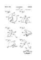
Figure 1 is a plan view of a blank of a type adapted for use in the formation of a tent in accordance with the invention;
Fig. 2 illustrates a pair of associated blanks ready for erection to form a tent;
Fig. 3 is a top view of the erected tent;
Fig. 4 is a front view thereof;
Fig. 5 is a view similar to Fig. 3 showing a portion of one blank turned back to provide a doorway;
Fig. 6 is a view similar to Fig. 4 showing a por-- tion of one blank turned back to provide a doorway;
Fig. 7 is a view similar to Fig. 6 showing a smaller portion of one blank turned back to provide a doorway;
Fig. 8 is a detail view showing a modified form of reinforcing means; and
Figs. 9 and 10 are top and side views, respectively, of a tent formed from a single one of the blanks illustrated in Fig. l.
The necessity for the use of poles, which considerably complicates the use of tents by persons other than habitual users and skilled campers, is attended by numerous transportation and other difiioulties. On the other hand, there is a wide field of use for tents which provide an effective semi-permanent shelter and the transportion of which is particularly easy and the cost not excessive. With these and other considerations in view, the present invention contemplates there is provided a hole the provision of a self-supporting tent which may nevertheless provide ample room and effective protection.
In accordance with the invention there is provided a tent composed of a plurality of sections 66 of semi-rigid flexible material, and a tent formed of semi-rigid flexible material a portion of which may be turned back to provide a doorway. Among the various semi-rigid flexible materials which may be used are various types of paper board, linoleum, strip roofing materials, building felt, etc. Suitable waterproofing substances may be embodied in or applied to the material when desired.
It has been found that a very satisfactory shape of tent is a generally conical one which may be formed of a plurality of pieces of material each having a generally arcuate edge. Desirably also, there is provided a generally conical structure wherein a portion of the material is turned back to provide a doorway. Preferably, this portion will include a portion adjacent a part of a generally arcuate edge at the base of the cone.
It is to be understood that the terms generally conical and generally arcuate, as used herein, are intended to include cones, distorted cones, pyramids, etc., and arcs and modified arcs, respectively and that other similar terms are to be similarly understood. It is also to be understood that the term flexible material includes material which may be bent along definite lines, as well as material which may be bowed.
One of the many varieties of possible embodiments of the invention is illustrated by way of example.
In Fig. 1 there is shown a blank 20 which, in the present instance, is in the form of a semicircle with one end cut away, and which comprises an arcuate edge 21 and straight edges 22 and 23, the straight edge 22 being longer than 5 the straight edge 23. Along the arcuate edge 21 there are provided holes 24, 25 and 26. Adjacent the junction of the edges 22 and 23 there is provided a hole 27 and at a point inwardly of this hole and nearer the edge 22 than the edge 23, 28. Preferably the holes are reinforced with metallic eyelet members. If desired the edge 21 may be in the form of a portion of a regular polygon or other modified are. If in the form of a regular polygon definite radial bend lines may be provided for the formation of a pyramidal structure.
In the present embodiment, the tent is formed of two blanks such as shown in Fig. 1. The two blanks 20a and 2019 are overlapped, as indicated in Fig.2, with the holes 24 and 27 of blank 20a associated with the holes 26 and 28' of blank 2%. Suitable fastening means, as the removable fastening member indicated at 29, is moved through the holes 27-28 and secured in place. A further fastening means may be inserted through the holes 24 in blank 20a and 26 in blank 2%, or a stake member, as indicated at 30, may be passed through these holes. The corner of the blank 2% containing the hole 27 is then lifted and this corner bent over the blank 2% so thatthis hole will register with the hole 28 on the blank 2%, and a fastening means 29 is inserted and secured. The holes 24 in the blank 20b and 26 in blank 20a may be secured by a fastening means 29 or stake member 30. Similar stake members may be passed through the holes 25 of which there may be any desired number. A doorway permitting access to the tent may be formed by removing the securing means from a point where the blanks are united adjacent their arcuate edges andfrom,
a point where they are united adjacent the apex of the tent, both these points being adjacent the shorter edge of one of the blanks. A portion of this blank adjacent this straight edge is then turned back, as indicated in Fig. 5. Cords, as indicated at 31 and 32, may be provided to maintain the portion of the blank in turned back position. If a smaller opening is provided. the fastener adjacent the apex may be left in place and merely the corner of the blank adjacent the junction of its shorter straight edge with its arcuate edge may be turned back, as indicated in Fig. '7. This may be similarly fastened back by a cord, if desired.
It will be appreciated that in many instances the straight edges of blanks need not meet at a right angle in order for the pieces to function in the exemplified manner. For example, the longer straight edge of each blank may follow a course such that the edge 22 of the blank 20b will be parallel to the edge 23 of the blank 20a in Fig. 2, whereby a tent having an upper opening may be formed. This opening may, if desired, be covered with translucent material such as transparent paper-like cellulose products or mosquito netting. Similarly, the shorter straight edges may be cut on a line varying in direction from that shown.
For transportation, the blanks may be suitably rolled, or, in certain instances, folded.
Various reinforcing and protective members may be provided. Each blank 20 may, for example, be provided with a reinforcing member 33 extending from the junction of the edges 21 and 22 and toward the junction of the edges 22 and 23, but terminating short of a point adjacent the apex of the tent. When the blanks are formed of cardboard or other easily torn material, the edge 23 and the portion of the edge 22 adjacent the edge 23 may be taped as indicated at 34 in Fig. 4 to prevent tearing. In instances where because of space requirements it is desirable to roll the blank or blanks on the shorter edge or edges thereof there may advantageously be substituted for the reinforcing member 33, a removable reinforcing member 35, as indicated in Fig. 8. As exemplified, this member is composed of a strip of metal with its longitudinal edge portions bent inwardly and the entire strip bent on a longitudinal axis so that it may readily be slid over the edge. Cords 36 extending through the hole 26 and an additional hole or holes such as the holes 37 may be utilized to detachably retain the member 35 inplace.
As will be understood, a multiplicity of pieces of material may be utilized in the formation of the tent in accordance with the invention; and a self-supporting tent arranged to provide a doorway when a portion of the material is turned back may be formed from one or more blanks as desired. The shape of blank or blanks provided may be suitably modified in accordance with the particular type of structure desired.
In certain cases it is of advantage that the particular blanks provided be adapted either to be associated with other blanks or to be utilized alone depending on the size and type of tent desired. Accordingly, the blank 20 is formed with an additional hole 38 somewhat nearer each longer straight edge and somewhat further from its shorter straight edge than the hole 23, so that the hole 27 of a blank may be juxtaposed with the hole 38 in the same blank and the blank gathered into tent form. A fastening means, such as 29, may be inserted through the juxtapositioned holes. Tents thus formed are illustrated in Figs. 9 and 10 and are of the general character of tents described in my co-pending application, Serial No. 496,596, filed November 19, 1930.
Since certain changes may be made in the above article and different embodiments of the invention could be made without departing from the scope thereof, it is intended that all matter contained-in the above description or shown in the accompanying drawings shall be interpreted as illustrative and not in a limiting sense.
It is also to be understood that the following claims are intended to cover all of the generic and specific features of the invention herein described, and all statements of the scope of the invention which, as a matter of language, might be said to fall therebetween.
Having described my invention, what I claim as new and desire to secure by Letters Patent is:
l. A tent comprising a plurality of sections of semi-rigid flexible material providing a generally conical enclosure, and means to detachably unite said sections including means to unite the sections at points above the base of the cone, said tent being self supporting without the use of poles.
2. A tent comprising a pair of sections of semirigid flexible material arranged to provide a generally conical enclosure, and means to detachably unite said sections including means to unite the sections at points above the base of the cone, said tent being self-supporting without the use of poles.
3. A tent of generally conical shape and comprising a plurality of members composed of semirigid flexible material and each having a generally arcuate edge and a pair of substantially straight edges of unequal length and joined with said arcuate edges at the base and with a portion adjacent the shorter straight edge of one mem ber and a portion adjacent the longer straight edge of another member in overlapping relationship, said tent being self-supporting without the use of poles.
4. A tent of generally conical shape comprising a pair of generally similar memberscomposed of semi-rigid flexible material and each having a generally arcuate edge and a pair of substantially straight edges of unequal length and joined with said arcuate edges at the base and with the portion adjacent the shorter straight edge of each member overlapping a portion adjacent the longer straight. edgeof the other member, said tent being self-supporting without the use of poles.
5. A tent of generally conical shape comprising a pair of generally similar members composed of semi-rigid flexible material and each having a generally arcuate edge and a pair of substantially straight edges of unequal length and joined with said arcuate edges at the base and with the portion adjacent the shorter straight edge of each member overlapping a portion adjacent the longer straight edge of the other member, and means to detachably unite said sections, said tent being self-supporting without the use of poles.
6. A tent of generally conical shape and comprising a pair of members composed of semi-rigid flexible material and each generally semi-circular in shape with one corner cut away and joined with the generally arcuate edges at the base and with a portion adjacent the cutaway portion of one member and a portion adjacent the other straight edge of the other member in overlapping relationship, said tent being self-supporting without the use of poles.
7. A tent comprising a plurality of sections of semi-rigid flexible material and means to detachably unite said sections in conical form to provide a structure which is self-supporting without the use of poles, each section having a generally arcuate edge and a substantially straight edge, portions of different sections overlapping, and means to unite said overlapping portions at a point above said base to permit a portion of one section to be turned. back to provide a doorway.
8. A tent of generally conical shape and comprising a plurality of members composed of semirigid flexible material and each having a generally arcuate edge and a pair of substantially straight edges of unequal length and joined with said arcuate edges at the base and with a portion adjacent the shorter straight edge of one member and a portion adjacent the longer straight edge of another member in overlapping relaitonship, said tent being self-supporting without the use of poles, and being provided with a doorway when a portion of one of said members is turned back.
9. A tent of generally conical shape comprising a pair of generally similar members composed of semi-rigid flexible material and each having a generally arcuate edge and a pair of substantially straight edges of unequal length and joined with said arcuate edges at the base and with the portion adjacent the shorter straight edge of each member overlapping a portion adjacent the longer straight edge of the other member, said tent being self-supporting without the use of poles, and being provided with a doorway when a portion of one of said sections is turned back.
10. A tent of generally conical shape and comprising a pair of members composed of semirigid flexible material and each generally semicircular in shape with one corner cut away and joined with the generally arcuate edges at the base and with a portion adjacent the cutaway portion of one member and a portion adjacent the other straight edge of the other member in overlapping relationship, said tent being selfsupporting without the use of poles, and being provided with a doorway when a portion of one of said sections is turned back.
11. A tent of generally conical shape comprising a pair of generally similar members composed of semi-rigid flexible material and each having a generally arcuate edge and a pair of substantially straight edges of unequal length and joined with said arcuate edges at the base and with the portion adjacent the shorter straight edge of each member overlapping a portion adjacent the longer straight edge of the other member, said tent being self-supporting without the use of poles and each of said members having a reinforcement extending along its longer straight edge from the junction of its arcuate edge and the longer straight edge to a point spaced from the junction of the straight edges.
12. A tent of generally conical shape formed of semi-rigid material and self-supporting without the use of poles and including a piece of material having an upwardly extending edge and a reinforcing member detachably secured to said edge.
13. A blank for use in the formation of tents, comprising semi-rigid material having a generally arcuate edge and straight edges of unequal length, and formed with holes at its corners and with a hole at a point disposed inwardly from the longer straight edge and a greater distance inwardly from the shorter straight edge and a still greater distance from the arcuate edge.
14. A blank for use in the formation of tents, comprising semi-rigid material having a generally arcuate edge and straight edges of unequal length, and formed with holes at its corners and with a hole at a point disposed inwardly from the longer straight edge and a greater distance inwardly from the shorter straight edge and at a still greater distance from the arcuate edge, and with an additional hole at a point nearer the longer straight edge and further from the shorter straight edge than the last-mentioned hole.
15. A tent comprising a pair of generally similar sections each composed of flexible semi-rigid material and having an arcuate edge and a pair of generally straight edges of unequal length meeting at a corner, and means to unite each section at a point adjacent itscorner to the body of the other section to provide a generally conical structure with the arcuate edges at the base of the structure.
BUTCHER. SKAGERBERG.
Priority Applications (1)
| Application Number | Priority Date | Filing Date | Title |
|---|---|---|---|
| US612726A US1953514A (en) | 1932-05-21 | 1932-05-21 | Tent |
Applications Claiming Priority (1)
| Application Number | Priority Date | Filing Date | Title |
|---|---|---|---|
| US612726A US1953514A (en) | 1932-05-21 | 1932-05-21 | Tent |
Publications (1)
| Publication Number | Publication Date |
|---|---|
| US1953514A true US1953514A (en) | 1934-04-03 |
Family
ID=24454401
Family Applications (1)
| Application Number | Title | Priority Date | Filing Date |
|---|---|---|---|
| US612726A Expired - Lifetime US1953514A (en) | 1932-05-21 | 1932-05-21 | Tent |
Country Status (1)
| Country | Link |
|---|---|
| US (1) | US1953514A (en) |
Cited By (4)
| Publication number | Priority date | Publication date | Assignee | Title |
|---|---|---|---|---|
| US2596442A (en) * | 1949-10-14 | 1952-05-13 | Melvin J Scholting | Tepee |
| US20170096834A1 (en) * | 2014-04-25 | 2017-04-06 | Designer Direct, Inc. d/b/a Levin Associates | Cantilevered Watercraft Canopy |
| US10272971B2 (en) | 2015-06-19 | 2019-04-30 | Designer Direct, Inc. | Watercraft canopy for U-shaped dock |
| US11952781B2 (en) | 2022-01-27 | 2024-04-09 | Designer Direct, Inc. | Watercraft canopy extension for existing covered dock |
-
1932
- 1932-05-21 US US612726A patent/US1953514A/en not_active Expired - Lifetime
Cited By (6)
| Publication number | Priority date | Publication date | Assignee | Title |
|---|---|---|---|---|
| US2596442A (en) * | 1949-10-14 | 1952-05-13 | Melvin J Scholting | Tepee |
| US20170096834A1 (en) * | 2014-04-25 | 2017-04-06 | Designer Direct, Inc. d/b/a Levin Associates | Cantilevered Watercraft Canopy |
| US9777504B2 (en) * | 2014-04-25 | 2017-10-03 | Designer Direct, Inc. | Cantilevered watercraft canopy |
| US10309096B2 (en) | 2014-04-25 | 2019-06-04 | Designer Direct, Inc. | Cantilevered watercraft canopy |
| US10272971B2 (en) | 2015-06-19 | 2019-04-30 | Designer Direct, Inc. | Watercraft canopy for U-shaped dock |
| US11952781B2 (en) | 2022-01-27 | 2024-04-09 | Designer Direct, Inc. | Watercraft canopy extension for existing covered dock |
Similar Documents
| Publication | Publication Date | Title |
|---|---|---|
| US4064662A (en) | Collapsible tetrahedral structure | |
| US8286809B2 (en) | Self-expanding folding structure for a display | |
| US2701089A (en) | Carton construction | |
| US3016115A (en) | Portable shelter | |
| EP0055505A2 (en) | Panel display | |
| US4425733A (en) | Fly paper | |
| US4317617A (en) | Traffic channeling device | |
| US1953514A (en) | Tent | |
| US2974434A (en) | Greeting card | |
| US4893745A (en) | Suspendable folder | |
| US5692714A (en) | Automatic self-erecting display stand | |
| US1881986A (en) | Display case | |
| US2055201A (en) | Knock-down display device | |
| EP2860122B1 (en) | Folding box | |
| US2935185A (en) | Snap-up book match folders | |
| US3244348A (en) | Container | |
| US1377788A (en) | Tent | |
| US3504841A (en) | Foldable packing bag | |
| US2204363A (en) | Metal awning | |
| US1925411A (en) | Tent | |
| US2326366A (en) | Paper fastener | |
| US3446221A (en) | Paper umbrella | |
| US4166529A (en) | Cylinder style display box | |
| DE102018132416B4 (en) | Shelf support for an open shelf | |
| US2120472A (en) | Window display |