US1920035A - Cutter bit and chuck - Google Patents
Cutter bit and chuck Download PDFInfo
- Publication number
- US1920035A US1920035A US590468A US59046832A US1920035A US 1920035 A US1920035 A US 1920035A US 590468 A US590468 A US 590468A US 59046832 A US59046832 A US 59046832A US 1920035 A US1920035 A US 1920035A
- Authority
- US
- United States
- Prior art keywords
- chuck
- socket
- bit
- jaws
- heads
- Prior art date
- Legal status (The legal status is an assumption and is not a legal conclusion. Google has not performed a legal analysis and makes no representation as to the accuracy of the status listed.)
- Expired - Lifetime
Links
- 238000005065 mining Methods 0.000 description 8
- 239000003245 coal Substances 0.000 description 3
- 238000010276 construction Methods 0.000 description 3
- 230000004048 modification Effects 0.000 description 2
- 238000012986 modification Methods 0.000 description 2
- 229910052729 chemical element Inorganic materials 0.000 description 1
- 230000000694 effects Effects 0.000 description 1
- 239000012634 fragment Substances 0.000 description 1
- 238000004519 manufacturing process Methods 0.000 description 1
Images
Classifications
-
- E—FIXED CONSTRUCTIONS
- E21—EARTH OR ROCK DRILLING; MINING
- E21C—MINING OR QUARRYING
- E21C35/00—Details of, or accessories for, machines for slitting or completely freeing the mineral from the seam, not provided for in groups E21C25/00 - E21C33/00, E21C37/00 or E21C39/00
- E21C35/18—Mining picks; Holders therefor
- E21C35/19—Means for fixing picks or holders
- E21C35/193—Means for fixing picks or holders using bolts as main fixing elements
-
- E—FIXED CONSTRUCTIONS
- E21—EARTH OR ROCK DRILLING; MINING
- E21C—MINING OR QUARRYING
- E21C35/00—Details of, or accessories for, machines for slitting or completely freeing the mineral from the seam, not provided for in groups E21C25/00 - E21C33/00, E21C37/00 or E21C39/00
- E21C35/18—Mining picks; Holders therefor
- E21C35/19—Means for fixing picks or holders
- E21C35/191—Means for fixing picks or holders for fixing holders
-
- Y—GENERAL TAGGING OF NEW TECHNOLOGICAL DEVELOPMENTS; GENERAL TAGGING OF CROSS-SECTIONAL TECHNOLOGIES SPANNING OVER SEVERAL SECTIONS OF THE IPC; TECHNICAL SUBJECTS COVERED BY FORMER USPC CROSS-REFERENCE ART COLLECTIONS [XRACs] AND DIGESTS
- Y10—TECHNICAL SUBJECTS COVERED BY FORMER USPC
- Y10T—TECHNICAL SUBJECTS COVERED BY FORMER US CLASSIFICATION
- Y10T279/00—Chucks or sockets
- Y10T279/17—Socket type
- Y10T279/17564—Loose jaws
-
- Y—GENERAL TAGGING OF NEW TECHNOLOGICAL DEVELOPMENTS; GENERAL TAGGING OF CROSS-SECTIONAL TECHNOLOGIES SPANNING OVER SEVERAL SECTIONS OF THE IPC; TECHNICAL SUBJECTS COVERED BY FORMER USPC CROSS-REFERENCE ART COLLECTIONS [XRACs] AND DIGESTS
- Y10—TECHNICAL SUBJECTS COVERED BY FORMER USPC
- Y10T—TECHNICAL SUBJECTS COVERED BY FORMER US CLASSIFICATION
- Y10T403/00—Joints and connections
- Y10T403/70—Interfitted members
- Y10T403/7041—Interfitted members including set screw
-
- Y—GENERAL TAGGING OF NEW TECHNOLOGICAL DEVELOPMENTS; GENERAL TAGGING OF CROSS-SECTIONAL TECHNOLOGIES SPANNING OVER SEVERAL SECTIONS OF THE IPC; TECHNICAL SUBJECTS COVERED BY FORMER USPC CROSS-REFERENCE ART COLLECTIONS [XRACs] AND DIGESTS
- Y10—TECHNICAL SUBJECTS COVERED BY FORMER USPC
- Y10T—TECHNICAL SUBJECTS COVERED BY FORMER US CLASSIFICATION
- Y10T407/00—Cutters, for shaping
- Y10T407/22—Cutters, for shaping including holder having seat for inserted tool
- Y10T407/2272—Cutters, for shaping including holder having seat for inserted tool with separate means to fasten tool to holder
- Y10T407/2282—Cutters, for shaping including holder having seat for inserted tool with separate means to fasten tool to holder including tool holding clamp and clamp actuator
-
- Y—GENERAL TAGGING OF NEW TECHNOLOGICAL DEVELOPMENTS; GENERAL TAGGING OF CROSS-SECTIONAL TECHNOLOGIES SPANNING OVER SEVERAL SECTIONS OF THE IPC; TECHNICAL SUBJECTS COVERED BY FORMER USPC CROSS-REFERENCE ART COLLECTIONS [XRACs] AND DIGESTS
- Y10—TECHNICAL SUBJECTS COVERED BY FORMER USPC
- Y10T—TECHNICAL SUBJECTS COVERED BY FORMER US CLASSIFICATION
- Y10T407/00—Cutters, for shaping
- Y10T407/23—Cutters, for shaping including tool having plural alternatively usable cutting edges
Definitions
- This invention relates to certain novel improvements in a cutter :bit. and" 'chuck-, -,and has for its principal'object the provisionof- I animproved construction ofythislcharacter which will behighly efficient in use and economical to manufacture.
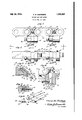
- Fig. 1 is a fragmentary sideelevational view of a mining machine chain showing the invention attached thereto;
- Fig. 2 is a plan view on line 2-2 in Fig. 1;
- Fig. '3 is a sectional view on lin 3-3 in Fig. 2;
- Fig. 4 is a sectional view on line 4-4 in Fig.3;
- Fig. 5 is a sectional view online 5-5 in Fig. 3;
- Fig. 6 is a perspective view'ofthe bit and i 20 of the chuck jaws 18.
- each of the chuck-holding ele ments12 thereis a bore or socket 17 for the 5 receptionof'my improved split cutter bit chuck which is generally indicated at 16 and which includes two similar bit-clamping jaws 18a. r .v
- Each of the chuck jaws 18 includes a tapered -stem19 and a bit-clamping head 20 and in each of the heads 20 there is a slot 1 21. These slots 21 cooperatewith each other,
- a limit pin 28 in the chuclcholding element 12 restricts projection of the chuck jaws 18 into. the bore or socket 17 in the chuck-holding element 12.
- the. chuck jawsl8 are tapered from end to end so that the head 20 of each chuck jaw 18is thicker than th heel portion 29 of each of said chuck jaws 18 where.- by when the screw 25 is adjusted to force 5 the head 26;thereof into the recess 27 the chuck jaws 18 will be pivoted about the end 30 of the chuck-holding element 12 as a fulcrum, thereby spreading the heels 29 of the chuck jaws 18 apart and forcing the heads 20 thereof together to clamp the head 24 of the bit 22 in the socket 21 between the heads
- the heads 20 of the chuck jaws 18 may be spread apart to withdraw the head 24L of bit 22 from the socket 31'whereby-the head 24 of thebit 22 having a used or dull edge 23 may-be removed from the socket 21 and 109 the-other head 24 of the bit havinga sharp .edge23 may be inserted into
- V -VVhi1e I have illustrated and described the preferred form of 'constructionfor carrying my invention into effect, this. isflcapable of variation and modification, without departing from the splrlt of the lnvention.
- each of said j aws including aclampinghead at the thickerend of the correspondlngstem
- each ofsaid heads "having a slotmextending 'thereinto from one edge thereof, said slots extending transversely of the long axes of said jaws andiprovidinga socket, each of said stems having a recess providedthereinv between its ends, a cutter bit includinga portlon rece1vable in@sa1d secondenamed socket, and an ad ustablemember carried by said holder having a portion penetrable into said recesses to wedge 'sald stems'apart at their thinner ends andfulcrum the latter against the wall of-the;firstnamedfsocket to forcesaid heads into clamping engagement with saidbit portion.
- a mining machine chuckholder having a socket formed therein, a chuck including a pair of bit-clamping jaws disposed in said socket and each including a; substantially flat stem tapered from end toend, each of said jaws including a clamping head at the thicker end of the corresponding stem,
- said holder having a portion penetrable into sald recesses to wedge-said stems apart at vbit portion) j 4.
- a chuck holder having a socket formed therein, a chuck ineach of said heads having a slot formed therein and said slots providing a socket, each of said stems having a recess provided therein between its ends, a cutter bit including a portion receivable in said secondnamed socket, and an adjustable member .carried by said holder having a portion penetrable into said recesses to Wedge said stems apart at theirthinner ends and fulcrum the latter against the wallof the first-named socket to force said heads into clamping engagement with said-bit portion.
- I11 a mining machine, achuck holder having asocket formed therein, a chuck including a pair of bit-clamping jaws disposed in-said socket and eaclrincluding a substantially flatstem tapered from end to e1 1d,'.each-ot said jaws including a clamping head at the thicker end of the corresponding stem, each of said stems having a recess provided thereinbetween-itsends, a cutter bit including apo'rtion disposablebetween said heads, and; an adjustable member carried by.-
Landscapes
- Engineering & Computer Science (AREA)
- Mining & Mineral Resources (AREA)
- Mechanical Engineering (AREA)
- Life Sciences & Earth Sciences (AREA)
- General Life Sciences & Earth Sciences (AREA)
- Geochemistry & Mineralogy (AREA)
- Geology (AREA)
- Drilling And Exploitation, And Mining Machines And Methods (AREA)
Description
July 25, 1933. M STEPHENS 1,920,035
CUTTER BIT AND CHUCK Filed Feb. 2, 1932 .1 Tia INVENTOR HIS ATTOR N EYS Patented July 25, 1933 I THo AsM. STEPHElNflOF. MICHIGAN or'rY, INDIANA PAT EEN J F i:c
CUTTER BIT AND cHu'oK Application filed. FebruarylZ, 1932.- Serial No. 590,468.
This inventionrelates to certain novel improvements in a cutter :bit. and" 'chuck-, -,and has for its principal'object the provisionof- I animproved construction ofythislcharacter which will behighly efficient in use and economical to manufacture. v I
It is an obj ect' ofthisinvention to provide animproved cutterrbit and chuck for coal mining machines.
1O ltlis another Object of the inventionto and easily reversed and, replaced in .the-
chuck. v vAnother'objectof the invention is to pro vide an improved cutter bit chuck'for. detachably mounting the cutter bit on the chain of a coal mining machine. 8 Other objects will appear hereinafter. The .inventionconsists in the novel. combination and arrangement, of parts to be hereinafter described and claimed. 5 q The invention will be best understood by reference to the accompanying, drawing,
showing the preferred form of construction and in which: 1;
Fig. 1 is a fragmentary sideelevational view of a mining machine chain showing the invention attached thereto; i
Fig. 2 is a plan view on line 2-2 in Fig. 1; Fig. '3 is a sectional view on lin 3-3 in Fig. 2;
Fig; 4 is a sectional view on line 4-4 in Fig.3; Fig. 5 is a sectional view online 5-5 in Fig. 3; and
' chuck.
I In the drawing, which illustrates a preferred and practicalembodiment of the invention, a fragment of a coal mining machine chain, such as the chains used on long:
wall machines, is illustratedgenerally at 10 Fig. 6 is a perspective view'ofthe bit and i 20 of the chuck jaws 18.
side which is an car 13 for-the reception: of the studs 15'by; which the'chuck holding ele ments 12 are pivotally connected in the chain 10. In each of the chuck-holding ele ments12 thereis a bore or socket 17 for the 5 receptionof'my improved split cutter bit chuck which is generally indicated at 16 and which includes two similar bit-clamping jaws 18a. r .v
Each of the chuck jaws 18 includes a tapered -stem19 and a bit-clamping head 20 and in each of the heads 20 there isa slot 1 21. These slots 21 cooperatewith each other,
when the jaws 18 are in the'bore or socket .17, to. provide a socket 3 l for the reception 6b of the cutter bit 22 whichhas two similar cuttingheads 24 each having acuttingedge 23 whereby ,either head-24 of the bit ma be disposed in-the socket 31.
.- -Carried by the chuck-holding element :12"
is an, adjustable memberor set screw 25 which. has a tapered. head 26 that is penetrable into; a correspondingly tapered recess 27 formed in the stems 19. of the chuck bit-' clamping jaws-18... i i 7 A limit pin 28 in the chuclcholding element 12 restricts projection of the chuck jaws 18 into. the bore or socket 17 in the chuck-holding element 12.
Byreference to Figs; 3-and 6 it will be. 9 notedthat the. chuck jawsl8 are tapered from end to end so that the head 20 of each chuck jaw 18is thicker than th heel portion 29 of each of said chuck jaws 18 where.- by when the screw 25 is adjusted to force 5 the head 26;thereof into the recess 27 the chuck jaws 18 will be pivoted about the end 30 of the chuck-holding element 12 as a fulcrum, thereby spreading the heels 29 of the chuck jaws 18 apart and forcing the heads 20 thereof together to clamp the head 24 of the bit 22 in the socket 21 between the heads By retracting the screw .25 so as to withdraw the head-26 thereof out of the recess 27 the heads 20 of the chuck jaws 18 may be spread apart to withdraw the head 24L of bit 22 from the socket 31'whereby-the head 24 of thebit 22 having a used or dull edge 23 may-be removed from the socket 21 and 109 the-other head 24 of the bit havinga sharp .edge23 may be inserted into the socket 21 and clamped therein by again adjusting the head-26 thereof into screw 25. force the the recess 27. j
V -VVhi1e I have illustrated and described the preferred form of 'constructionfor carrying my invention into effect, this. isflcapable of variation and modification, without departing from the splrlt of the lnvention.
the appended claims. Having thus' described my invention what I claim as new and desire toprotect by'Letters Patent' is: r I 1. In a mining mach1ne, a chuck 'holder having a socket formed therein, a chuck including a pair of bit-clamping jaws disposed in said socket and each including a substan-. tially fiat stem. tapered fromend toend,
each of said j aws including aclampinghead at the thickerend of the correspondlngstem,
each ofsaid: heads "having a slotmextending 'thereinto from one edge thereof, said slots extending transversely of the long axes of said jaws andiprovidinga socket, each of said stems having a recess providedthereinv between its ends, a cutter bit includinga portlon rece1vable in@sa1d secondenamed socket, and an ad ustablemember carried by said holder having a portion penetrable into said recesses to wedge 'sald stems'apart at their thinner ends andfulcrum the latter against the wall of-the;firstnamedfsocket to forcesaid heads into clamping engagement with saidbit portion. i
2.111 a mining machine, chuckholder having a socket formed therein, a chuck including a pair of bit-clamping jaws disposed in said socket and each including a; substantially flat stem tapered from end toend, each of said jaws including a clamping head at the thicker end of the corresponding stem,
I, therefore, do not-wish to be limited to the precise details of construction set forth, but desire to avail myself of such variations and modifications as come within the' sc'ope of,
said holder having a portion penetrable into sald recesses to wedge-said stems apart at vbit portion) j 4. In-a mining machine, a chuck holder 'having a socket formed therein, a chuck ineach of said heads having a slot formed therein and said slots providing a socket, each of said stems having a recess provided therein between its ends, a cutter bit including a portion receivable in said secondnamed socket, and an adjustable member .carried by said holder having a portion penetrable into said recesses to Wedge said stems apart at theirthinner ends and fulcrum the latter against the wallof the first-named socket to force said heads into clamping engagement with said-bit portion.
3. I11 a mining machine, achuck holder having asocket formed therein, a chuck including a pair of bit-clamping jaws disposed in-said socket and eaclrincluding a substantially flatstem tapered from end to e1 1d,'.each-ot said jaws including a clamping head at the thicker end of the corresponding stem, each of said stems having a recess provided thereinbetween-itsends, a cutter bit including apo'rtion disposablebetween said heads, and; an adjustable member carried by.-
their thinner; ends and fulcrum the latter against.thefwall oi sald socket'to force said heads 1nto clamping engagement with said eluding a'pair of bit clamping jaws disposed in said socket and each including a substantiallyfiat stem tapered from end to end, each of said jaws including a clamping headat the thicker end of the corresponding stem, acutter bitincluding' a portion disposable between said heads, and anadjustable member carried by said holder between" the ends ofsaid stems having a portion penetrable between said stems to Wedge said stems apart at tl1e1rth1nner ends and fulcrum the latter againstjthewall of said socket to force said heads into clamping engagement with said 1110
Priority Applications (1)
| Application Number | Priority Date | Filing Date | Title |
|---|---|---|---|
| US590468A US1920035A (en) | 1932-02-02 | 1932-02-02 | Cutter bit and chuck |
Applications Claiming Priority (1)
| Application Number | Priority Date | Filing Date | Title |
|---|---|---|---|
| US590468A US1920035A (en) | 1932-02-02 | 1932-02-02 | Cutter bit and chuck |
Publications (1)
| Publication Number | Publication Date |
|---|---|
| US1920035A true US1920035A (en) | 1933-07-25 |
Family
ID=24362385
Family Applications (1)
| Application Number | Title | Priority Date | Filing Date |
|---|---|---|---|
| US590468A Expired - Lifetime US1920035A (en) | 1932-02-02 | 1932-02-02 | Cutter bit and chuck |
Country Status (1)
| Country | Link |
|---|---|
| US (1) | US1920035A (en) |
Cited By (8)
| Publication number | Priority date | Publication date | Assignee | Title |
|---|---|---|---|---|
| US2416774A (en) * | 1943-05-22 | 1947-03-04 | Rosenblatt David | Chuck and means for attaching tools thereto |
| US2529788A (en) * | 1948-07-06 | 1950-11-14 | Carl A Signell | Drill |
| US2675219A (en) * | 1946-10-14 | 1954-04-13 | Austin Hoy & Co Ltd | Coal cutter chain |
| US2838827A (en) * | 1955-07-11 | 1958-06-17 | John H Wright | Cutting tool |
| US2853283A (en) * | 1954-09-02 | 1958-09-23 | James A Cook | Pick boxes for coal and like cutting machines |
| US2924260A (en) * | 1957-07-05 | 1960-02-09 | Nicholas A Guarino | Gauge for sheet metal working presses |
| US3180006A (en) * | 1959-08-13 | 1965-04-27 | U S Tool And Cutter Company | Grooving tool |
| US3466720A (en) * | 1967-11-08 | 1969-09-16 | Carmet Co | Reversible throw-away cutting inserts |
-
1932
- 1932-02-02 US US590468A patent/US1920035A/en not_active Expired - Lifetime
Cited By (8)
| Publication number | Priority date | Publication date | Assignee | Title |
|---|---|---|---|---|
| US2416774A (en) * | 1943-05-22 | 1947-03-04 | Rosenblatt David | Chuck and means for attaching tools thereto |
| US2675219A (en) * | 1946-10-14 | 1954-04-13 | Austin Hoy & Co Ltd | Coal cutter chain |
| US2529788A (en) * | 1948-07-06 | 1950-11-14 | Carl A Signell | Drill |
| US2853283A (en) * | 1954-09-02 | 1958-09-23 | James A Cook | Pick boxes for coal and like cutting machines |
| US2838827A (en) * | 1955-07-11 | 1958-06-17 | John H Wright | Cutting tool |
| US2924260A (en) * | 1957-07-05 | 1960-02-09 | Nicholas A Guarino | Gauge for sheet metal working presses |
| US3180006A (en) * | 1959-08-13 | 1965-04-27 | U S Tool And Cutter Company | Grooving tool |
| US3466720A (en) * | 1967-11-08 | 1969-09-16 | Carmet Co | Reversible throw-away cutting inserts |
Similar Documents
| Publication | Publication Date | Title |
|---|---|---|
| US1920035A (en) | Cutter bit and chuck | |
| US1244785A (en) | Mining-machine chain. | |
| US2289464A (en) | Kerf cutting device | |
| US1672458A (en) | Tool for removing and inserting saw teeth | |
| US2070217A (en) | Tool | |
| US1423713A (en) | Detachable bit for drills | |
| US1484332A (en) | Tool holder | |
| US2183581A (en) | Cutter chain | |
| US1926047A (en) | Cutter chain | |
| US1427550A (en) | Jawed tool | |
| US2263590A (en) | Cutter chain | |
| US1828523A (en) | Stud setter | |
| US2244199A (en) | Cutter chain | |
| US2211525A (en) | Mine machinery cutting bit and mounting therefor | |
| US1468914A (en) | Chain cutter for mining machines | |
| US1487217A (en) | Mining-machine bit | |
| US1374278A (en) | Device for cutting wire cable | |
| US2039416A (en) | Cutter chain | |
| US2711892A (en) | Coal cutting bit having carbide insert | |
| US2043999A (en) | Dental matrix holder | |
| US1586021A (en) | Cutter chain | |
| US2387285A (en) | Cutter chain | |
| US1548745A (en) | Cutter chain | |
| US1795804A (en) | Mining-machine bit and bit holder | |
| US1331840A (en) | Tqol-b |