US190893A - Improvement in spring air-guns - Google Patents
Improvement in spring air-guns Download PDFInfo
- Publication number
- US190893A US190893A US190893DA US190893A US 190893 A US190893 A US 190893A US 190893D A US190893D A US 190893DA US 190893 A US190893 A US 190893A
- Authority
- US
- United States
- Prior art keywords
- piston
- spring
- cylinder
- barrel
- guns
- Prior art date
- Legal status (The legal status is an assumption and is not a legal conclusion. Google has not performed a legal analysis and makes no representation as to the accuracy of the status listed.)
- Expired - Lifetime
Links
- 238000010276 construction Methods 0.000 description 4
- 239000007787 solid Substances 0.000 description 3
- 229940000425 combination drug Drugs 0.000 description 1
- 210000003128 head Anatomy 0.000 description 1
- 230000002035 prolonged effect Effects 0.000 description 1
- 231100000241 scar Toxicity 0.000 description 1
Images
Classifications
-
- F—MECHANICAL ENGINEERING; LIGHTING; HEATING; WEAPONS; BLASTING
- F41—WEAPONS
- F41B—WEAPONS FOR PROJECTING MISSILES WITHOUT USE OF EXPLOSIVE OR COMBUSTIBLE PROPELLANT CHARGE; WEAPONS NOT OTHERWISE PROVIDED FOR
- F41B11/00—Compressed-gas guns, e.g. air guns; Steam guns
- F41B11/60—Compressed-gas guns, e.g. air guns; Steam guns characterised by the supply of compressed gas
- F41B11/64—Compressed-gas guns, e.g. air guns; Steam guns characterised by the supply of compressed gas having a piston effecting a compressor stroke during the firing of each shot
- F41B11/642—Compressed-gas guns, e.g. air guns; Steam guns characterised by the supply of compressed gas having a piston effecting a compressor stroke during the firing of each shot the piston being spring operated
- F41B11/646—Arrangements for putting the spring under tension
- F41B11/647—Arrangements for putting the spring under tension by a rocker lever
Definitions
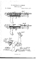
- Figure 1 of the drawings is a representation of a central vertical section of our pistol, and Fig. 2 is a side elevation of the same. Fig. 3 is a rear view thereof. Fig. 4 is a side view, part sectional, of our pistol.
- This invention relates to small arms for the projection of missiles, and more especially to pistols.
- the nature of said invention consists mainly. in the employment of a spring-operated piston, in combination with a barrel having a loadin g-opening near its cylinder, so as to leave an air-space or air-cushion between the said piston and the dart or other missile.
- the said weapon may be prepared for discharge either by draft applied at the breech thereof or pressure applied near the front of cylinder.
- A designates the butt of a pistol embodying my invention, which butt is cast in one piece with a cylinder,
- a ring, E On the rear end of said rod C is formed a ring, E, and also a cross-bar, e, which connects said rod C to another and longer rod, F, parallel therewith.
- Said rod F passes through lugs or eyes ff, rigidly connected to cylinder B, near the front and rear thereof, and carries at its front end, which is prolonged some distance beyond said barrel, a disk, G.
- Said rods C and F, cross-bar e, and ring E are preferably constructed in one piece.
- K designates a cylindrical barrel, which is detachably secured to the solid front end of said cylinder B by screwingits screw-threaded rear end into a correspondingly-threaded perforation in the same.
- Said barrel is provided in its top, near the cylinder, with an opening, It, through which the missile is introduced.
- Said arm or bar is longitudinally slotted at L, so as to guide a stud, G, formed on the upper part of disk G.
- Said stud engages with an annular flange, m, on a loose sleeve, M, which slides longitudinally on said barrel K.
- the said sleeve M covers opening it, through which the dart or other missile is introduced, as described.
- a cylindrical casing or shield, N surrounding a helical spring, 0, which is wound about rod F, and bears at its front end against a shoulder or enlarged forward part, F, of the same.
- the impulse thus given is communicated, through the body of air in barrel K, to the missile introduced, as above described, which is thus expelled with considerable force.
- the degree of said force depends mainly upon the strength of spring E, the amount of friction between piston D and the inside of cylinder B, and the more or less perfectly air-tight construction and connection of the said cylinder and barrel K.
- the above-described invention may be applied, with slight mechanical changes, to guns as well as pistols, and to toys as well as weapons of offense.
- Fig. 4 shows distinctly the construction of scar H and trigger I.
- the upper end of said sear is provided with a short born or catch, h, at an angle thereto, which horn retains piston D until released thereform by trigger I.
- the other end of said sear sets into a rectangular recess, t, in the nearer angle of said trigger, which is approximately triangular in shape.
- I designates the solid trigger-guard protecting both sides of the trigger, i the set-screw for said trigger, and h the sear-spring.
- Rods 0 and F, cross-bar a, ring E, and disk G rigidly attached, substantially as and for the purpose set forth.
- a pistol provided with an impelling-piston and piston-rod, in combination with devices, substantially as described, attached thereto, whereby the said pistol may be cooked either by pressure applied near the front of cylinder or by draft applied at the breech.
Landscapes
- Engineering & Computer Science (AREA)
- General Engineering & Computer Science (AREA)
- Toys (AREA)
Description
P. O'CONNOR & J. J. IDINNAN.
SPRING AIR-GUN.
NO. 190,893. Patented May 15 1877.
IT E8 E8 a W' -Qo.
W ATTORNEYS- I 6 d NvENToRs, %(Z@W6 N.PETERS, PHOTO-LITHUGRAPHER. WASHXNQTON. D C.
UNITED STATES PATENT OFFICE.
PATRICK CCONNOR AND JOHN J. DINNAN, OF NEW HAVEN, CONNECTICUT.
IMPROVEMENT IN SPRING AIR-GUNS.
Specification forming part of Letters Patent No. 190,898, dated May 15, 1877; application filed January 6, 1877.
To all whom it may concern:
Be it known that we, PATRICK OOoNNoR and JOHN J. DINNAN, of New Haven, in the county of New Haven and State of Connecticut, have invented a new and valuable 111lprovement in Pistols; and we do .hereby declare that the following is'a full, clear, and exact description of the construction and operation of the same, reference being had to the annexed drawings, making a part of this specification, and to the letters and figures of reference marked thereon.
Figure 1 of the drawings is a representation of a central vertical section of our pistol, and Fig. 2 is a side elevation of the same. Fig. 3 is a rear view thereof. Fig. 4 is a side view, part sectional, of our pistol.
This invention relates to small arms for the projection of missiles, and more especially to pistols.
The nature of said invention consists mainly. in the employment of a spring-operated piston, in combination with a barrel having a loadin g-opening near its cylinder, so as to leave an air-space or air-cushion between the said piston and the dart or other missile.
It also consists in certain devices and com binations, whereby the said weapon may be prepared for discharge either by draft applied at the breech thereof or pressure applied near the front of cylinder.-
It also consists in certain devices for uncovering the loading-opening by the same movement that prepares the spring and piston for discharge.
It also consists in certain devices for causing and facilitating the replacement of said uncovering and cocking devices.
In the accompanying drawings, A designates the butt of a pistol embodying my invention, which butt is cast in one piece with a cylinder,
B. The rear of said cylinder is closed by a breech and piston, is placed a helical spring, E, which is compressed whenever said piston is drawn back by the backward movement of rod C. This may be effected in two different ways by the devices hereinafter described.
On the rear end of said rod C is formed a ring, E, and also a cross-bar, e, which connects said rod C to another and longer rod, F, parallel therewith. Said rod F passes through lugs or eyes ff, rigidly connected to cylinder B, near the front and rear thereof, and carries at its front end, which is prolonged some distance beyond said barrel, a disk, G. Said rods C and F, cross-bar e, and ring E are preferably constructed in one piece. When draft is applied to ring E or pressure to disk G, rod C and piston D are forced backward, and spring E is compressed.
The said piston in such backward motion passes over the inwardly-extending point of a sear or catch, H, which is pivoted within the under part of said cylinder B, and adapted to be tripped by a trigger, I. Said sear looks or holds piston D against the expansive force of spring E until thus tripped by pressing the finger upon said trigger, in the usual manner.
K designates a cylindrical barrel, which is detachably secured to the solid front end of said cylinder B by screwingits screw-threaded rear end into a correspondingly-threaded perforation in the same. Said barrel is provided in its top, near the cylinder, with an opening, It, through which the missile is introduced. The said barrel Kis braced and supported by a perforated block, I, on a bar or rigid arm, L, which bar is made solid with said cylinder B, or rigidly attached thereto, and extends forward directly under said barrel K. Said arm or bar is longitudinally slotted at L, so as to guide a stud, G, formed on the upper part of disk G. Said stud engages with an annular flange, m, on a loose sleeve, M, which slides longitudinally on said barrel K. When in its most forward position, the said sleeve M covers opening it, through which the dart or other missile is introduced, as described.
Between perforated lugs 01' eyes ff is placed a cylindrical casing or shield, N, surrounding a helical spring, 0, which is wound about rod F, and bears at its front end against a shoulder or enlarged forward part, F, of the same.
The operation of the above-described devices is as follows: In loading, the operator forces or draws back the rods 0 and F, as hereinbefore described, until the piston I) iscocked or locked by the sear H, and the seeve M is removed by stud or finger G from opening 70. The said rods are then released, when spring 0 throws them forward into their normal position, the head or disk cof piston-rod 0 passing freely along the inside of tube 0. The missile is then introduced into opening k, and sleeve M is slipped back over the same. When aim has been taken, the trigger I is pressed, releasing piston D from sear H, and springE then throws said piston forward. The impulse thus given is communicated, through the body of air in barrel K, to the missile introduced, as above described, which is thus expelled with considerable force. The degree of said force depends mainly upon the strength of spring E, the amount of friction between piston D and the inside of cylinder B, and the more or less perfectly air-tight construction and connection of the said cylinder and barrel K.
The above-described invention may be applied, with slight mechanical changes, to guns as well as pistols, and to toys as well as weapons of offense.
By the construction above described we are enabled to load near the cylinder, and still impart to the missile almost the full force of the spring E. The interposed air-space or cushion preserves both said missile and piston D from being injured or worn by use. We are also enabled to employ a smaller barrel, K, than would be possible if the spring-operated piston D impinged directly against said missile.
Fig. 4 shows distinctly the construction of scar H and trigger I. The upper end of said sear is provided with a short born or catch, h, at an angle thereto, which horn retains piston D until released thereform by trigger I. The other end of said sear sets into a rectangular recess, t, in the nearer angle of said trigger, which is approximately triangular in shape. I designates the solid trigger-guard protecting both sides of the trigger, i the set-screw for said trigger, and h the sear-spring.
What we claim as new, and desire to secure by Letters Patent, 154-- 1. Rods 0 and F, cross-bar a, ring E, and disk G rigidly attached, substantially as and for the purpose set forth.
2. Beds 0 and F, cross-bar e, and ring E, in combination with replacing-spring O and tube 0, substantially as set forth.
3. The combination of barrelK, havingopening k, with sleeve M, having annnular flange m, stud or finger G on disk G, rods 0 and F, piston D, and spring 0, substantially as described.
4. The combination of spring-retracted rod F, carrying stud or finger G, with flanged sleeve M and slotted or perforated barrel K, substantially as described.
5. A pistol provided with an impelling-piston and piston-rod, in combination with devices, substantially as described, attached thereto, whereby the said pistol may be cooked either by pressure applied near the front of cylinder or by draft applied at the breech.
6. The combination of trigger I, having guard I, set-screw '11, and recess 5, with sear H, having born or catch h, and sear-sprin g h, substantially as set forth.
In testimony that we claim the above we have hereunto subscribed our names in the presence of two witnesses.
PATRICK OOONNOB. JOHN J. DINNAN. Witnesses:
O. T. DRISOOLL, ADOLPH ASHER.
Publications (1)
| Publication Number | Publication Date |
|---|---|
| US190893A true US190893A (en) | 1877-05-15 |
Family
ID=2260300
Family Applications (1)
| Application Number | Title | Priority Date | Filing Date |
|---|---|---|---|
| US190893D Expired - Lifetime US190893A (en) | Improvement in spring air-guns |
Country Status (1)
| Country | Link |
|---|---|
| US (1) | US190893A (en) |
Cited By (3)
| Publication number | Priority date | Publication date | Assignee | Title |
|---|---|---|---|---|
| US2526305A (en) * | 1947-09-30 | 1950-10-17 | George E Van Blarcom | Air pistol |
| US2773494A (en) * | 1953-07-06 | 1956-12-11 | Thompson Theodore Lester | Fishing line casting guns |
| US9389042B1 (en) | 2012-10-02 | 2016-07-12 | Richard A. Clayton | Projectile launchers |
-
0
- US US190893D patent/US190893A/en not_active Expired - Lifetime
Cited By (3)
| Publication number | Priority date | Publication date | Assignee | Title |
|---|---|---|---|---|
| US2526305A (en) * | 1947-09-30 | 1950-10-17 | George E Van Blarcom | Air pistol |
| US2773494A (en) * | 1953-07-06 | 1956-12-11 | Thompson Theodore Lester | Fishing line casting guns |
| US9389042B1 (en) | 2012-10-02 | 2016-07-12 | Richard A. Clayton | Projectile launchers |
Similar Documents
| Publication | Publication Date | Title |
|---|---|---|
| US190893A (en) | Improvement in spring air-guns | |
| US1026303A (en) | Repeating air-rifle. | |
| US179526A (en) | Improvement in toy pistols | |
| US1029469A (en) | Toy gun. | |
| US1045373A (en) | High-power air-rifle. | |
| US188028A (en) | Enbtjsh | |
| US183124A (en) | Improvement in toy pistols | |
| US227789A (en) | Albert g | |
| US1116675A (en) | Air-gun. | |
| US182899A (en) | Improvement in spring air-pistols | |
| US408971A (en) | Half to roswell l | |
| US834354A (en) | Magazine-firearm. | |
| US911683A (en) | Breech-loading safety-gun. | |
| US1080170A (en) | Air-gun. | |
| US786099A (en) | Repeating pistol. | |
| US1276078A (en) | Toy cannon. | |
| US157336A (en) | Improvement in toy pistols | |
| US984072A (en) | Air-gun. | |
| US153689A (en) | Improvement in toy guns | |
| US105093A (en) | Julius kraffert | |
| US2112946A (en) | Toy pistol | |
| US390311A (en) | Spring air-gun | |
| US767968A (en) | Spring air-gun. | |
| US493987A (en) | Mechanism for firing breech loading ordnance | |
| US901043A (en) | Safety-gun. |