US1908820A - Engine cowling - Google Patents
Engine cowling Download PDFInfo
- Publication number
- US1908820A US1908820A US539026A US53902631A US1908820A US 1908820 A US1908820 A US 1908820A US 539026 A US539026 A US 539026A US 53902631 A US53902631 A US 53902631A US 1908820 A US1908820 A US 1908820A
- Authority
- US
- United States
- Prior art keywords
- propeller
- hub
- vanes
- spinner
- shell
- Prior art date
- Legal status (The legal status is an assumption and is not a legal conclusion. Google has not performed a legal analysis and makes no representation as to the accuracy of the status listed.)
- Expired - Lifetime
Links
- 238000001816 cooling Methods 0.000 description 8
- 238000010276 construction Methods 0.000 description 7
- 230000003014 reinforcing effect Effects 0.000 description 4
- 238000012360 testing method Methods 0.000 description 4
- 230000009172 bursting Effects 0.000 description 2
- UQMRAFJOBWOFNS-UHFFFAOYSA-N butyl 2-(2,4-dichlorophenoxy)acetate Chemical compound CCCCOC(=O)COC1=CC=C(Cl)C=C1Cl UQMRAFJOBWOFNS-UHFFFAOYSA-N 0.000 description 2
- 238000006073 displacement reaction Methods 0.000 description 2
- 230000002787 reinforcement Effects 0.000 description 2
- 210000001015 abdomen Anatomy 0.000 description 1
- 239000011324 bead Substances 0.000 description 1
- 210000001217 buttock Anatomy 0.000 description 1
- 239000000110 cooling liquid Substances 0.000 description 1
- 238000002474 experimental method Methods 0.000 description 1
- 238000005086 pumping Methods 0.000 description 1
- 238000010792 warming Methods 0.000 description 1
Images


Classifications
-
- B—PERFORMING OPERATIONS; TRANSPORTING
- B64—AIRCRAFT; AVIATION; COSMONAUTICS
- B64D—EQUIPMENT FOR FITTING IN OR TO AIRCRAFT; FLIGHT SUITS; PARACHUTES; ARRANGEMENT OR MOUNTING OF POWER PLANTS OR PROPULSION TRANSMISSIONS IN AIRCRAFT
- B64D33/00—Arrangement in aircraft of power plant parts or auxiliaries not otherwise provided for
- B64D33/08—Arrangement in aircraft of power plant parts or auxiliaries not otherwise provided for of power plant cooling systems
Definitions
- This invention comprises improvements in the cooling and cowling of aircraft engines of the general type disclosed in my copending application Serial No. 501,789, filed December 12, 1930.
- Thevpresent invention accordingly relates to a streamlinecowling for an engine wherein the nose portion of the cowling comprises a spinner or cooling air blower organized for rotation with the propeller.
- the rotating or spinner part of the cowl is slotted for the propeller blades, and reinforcement against I centrifugal burstingat the slot is one of the problems involved.
- this was achieved by means of a baokplate having aflange embracing the outside of the spinner, the plate being provided with circumferential air delivery ports, leaving spokelike portions of the disc between the ports to provide the necessary reinforcement.
- greater exit area for the air than there'provided will increase the efiiciency of the device, and the present invention accordingly provides an improved construction giving greater strength against bursting and much enlarged air flow areas.'
- propeller blades themselves were at first relied on to act as vanes to impress rotation on the air in order to develop centrifugal pump ing action, although it was known that the air 49 displacement could be increased by the use of additional vanes so that the spinner is divided into more than two compartments,-'and so that the considerable slippage due to the failure of the standard propeller blade to fill 5 the spinner is eliminated.
- the tests have shown that to'give better-than-normal cooling in still air, such increased displacement is necessary; and accordingly the present invention provides a construction whereby a plurality of blower vanes may be associated 1931.
- Fig. 1 is a longitudinal section through the 65 cowling and spinner on the line 11 of Fig.
- Fig. 2 is a front elevation of the engine in section through the fixed part of the cowl on line 22 in Fig. 1.
- Fig. 3 is-a front elevation of the assembled cowl propeller.
- Fig. 1O desi nates the engine crankcase and 12 the cylin ers thereon, the intercylinder spaces being blanked off by bellies 14 and 16 adapted to restrict the air flow to the finned periphery of the engine cylinders and thus reduce the total volume of air required;
- the crankshaft of the engine 7 projects at 18 in the usual way and is equipped with a standard-propeller hub 20 having standard propeller blades 22, it being an object of this invention ,to equip existing engines without change to the propeller or 7 other parts.
- the propeller hub nut 24, however, may be lengthened in order to accommodate an additional nut 26 by which the blower vane hub 28 may be pinched onto the propeller hub. It will be seen that this blower vane hub 28 is cut out on two opposite sides to pass the propeller blade bosses of the propeller hub.
- a plate 30 having an external flange 32 fitted over a pilot turned on the blower vane hub 28 is provided, the plate 30 being piloted on the propeller hub at 34c to maintain the parts in concentric relation.
- a second plate 36 is secured to the plate 32 and provided with a pair of 2&1111838 located substantially behind the propeller blades 22 and these arms or spokes extend to the periphery of the spinner shell 40 whereat the arms are provided with arcuate extensions 42 which are bolted to the spinner to form a demountable reinforcing bridge closing the end of the slots 44 which must be cut in the spinner 40 to permit assembly of the propeller.
- the arms or spokes 38 and their arcuate ends 42 100 reinforce the spinner against both radial and circumferential loads. It will be seen that the spinner 40 is inwardly beaded at 46 to define an axial air inlet.
- the blower vane hub 28 is provided with a plurality of helically disposed ribs 48, to
- vanes 50 which are riveted the. inner ends of a plurality of pitched blower vanes 50. These vanes are provided with flanges 52 at their outer ends, accurately conformed to the desired streamline contour of the spinner shell 40, to which these flanges 52 are firmly secured by riveting.
- vanes are first riveted to the helical ribs 48 and'then the hub 28 is located on a jig having an accurate arcuatecontour over which the flanging operation 52 may be done on each blade in succession and to insure the uniformity essential for true running of the spinner.
- the best pitch angle for the vanes 50 depends upon the relative air velocity and, theo-.
- the spinner is reinforced against centrifugal stresses with a minimum of obstruction to the air flow and that a construction is provided whereby great accuracy and rigiditv are given to the surface of the spinner. This is important because a slight wabble in the'spinner is very noticeable in operation. causing a very bad appearance and being apt to upset the balance which must be accurately maintained.
- the fixed cowl may be suitably reinforced. at its front -end as bythe bead 64 and angle ring 66.
- a propeller having blades extending through said slots, a vane hub secured to the propeller, and vanes secured to said hub and to said shell.
- an open-ended conical shell having helical slots towards its larger diameter
- a propeller having blades extending through-the said slots
- vane hub secured to the propeller
- vanes secured to said hub and to said shell
- a radial armed member secured to the hub and having reinforcing bridges secured across .the' otherwise open ends of said slots.
- suitable cooling liquid may be disposed with- 9.
- a detacliablespinner for an aircraft propeller including a spinner hub adapt-ed to embrace the propeller hub, an outer slielltlirongli which the propeller blades extend, and vanes extending from one to the other of and fastened to said spinner hub and shell.
- a spinner for an aircraft propeller including a spinner hub, an enter siiell having slots formed therein through the propeller'blades extend, means extending redially out from said hub to reinforce said shell in the vicinity of said slots, abd vanes extending from one to the other of and fastened to said hub and shell; N
- a spinner for an aircraft propeller including a spinner bnb, enter email through which the propeller blades extend, and blower vanes pitcliedat a steeper angle than the pitcb angle of the propeller blades extendmg from one to the other of said spinner parts, said vanes, hub and outer shell bein bodily removable as a unit.
- a spinner for an aircraft propeller including a spinner hub, an'outer shell provided at its forward end with "an air inlet opening, and blower vanes extending radiali 1y out from said hub and fastened to said shell behind said opening, said bub, shell and v blower vanes being. adapted for attachment to and removal from said propeller as a unit.
- vanes for tacbed to and to enclose the hub of sold a propeller, and blower vanes attached to and extending outwardly from said bub.
Landscapes
- Engineering & Computer Science (AREA)
- Chemical & Material Sciences (AREA)
- Combustion & Propulsion (AREA)
- Mechanical Engineering (AREA)
- Aviation & Aerospace Engineering (AREA)
- Structures Of Non-Positive Displacement Pumps (AREA)
Description
May 16, 1933. I R CHILTON I 1,908,320
ENGINE ICOWLING- Filed May 21, 1931 3 SheetS-Sheet l 62 60 2 11v VEN TOR. Razmvp 67/1172? IATTOR May 16, 1933.
R. CHILTON ENGINE COWLING Filed May 21, 1931 3 Sheets-Sheet 2 INVENTOR. B OIHND 671m ATTORN R. CHILTON ENGINE COWLING May 16, 1933.
Filed May 21, 1931 s Sheets-Slieet- 3 INVENTOR. 'Eazfi/vz 07117019 Patented May 16, 1933 UNITED STATES PATENT OFFICE ROLAND CHILTON, F RIDGEWOOD, NEW JERSEY, ASSIGNOR TO WRIGHT AERONAUTICAL CORPORATION, A CORPORATION OF NEW YORK ENGINE cowrme Application filed May 21,
This invention comprises improvements in the cooling and cowling of aircraft engines of the general type disclosed in my copending application Serial No. 501,789, filed December 12, 1930. Thevpresent invention accordingly relates to a streamlinecowling for an engine wherein the nose portion of the cowling comprises a spinner or cooling air blower organized for rotation with the propeller. In such constructions the rotating or spinner part of the cowl is slotted for the propeller blades, and reinforcement against I centrifugal burstingat the slot is one of the problems involved. In the showing ofthe copending case this was achieved by means of a baokplate having aflange embracing the outside of the spinner, the plate being provided with circumferential air delivery ports, leaving spokelike portions of the disc between the ports to provide the necessary reinforcement. Experience has shown that greater exit area for the air than there'provided will increase the efiiciency of the device, and the present invention accordingly provides an improved construction giving greater strength against bursting and much enlarged air flow areas.'
While the construction shown in the copending case has been found to give better 39 than normal cooling with the assistance of an air blast as encountered in actual flight,-
it is desired to improve the elliciency until equalcooling is obtained in still air such as is encountered in ground testing the engine. In
the tests of the previous construction, the
propeller blades themselves were at first relied on to act as vanes to impress rotation on the air in order to develop centrifugal pump ing action, although it was known that the air 49 displacement could be increased by the use of additional vanes so that the spinner is divided into more than two compartments,-'and so that the considerable slippage due to the failure of the standard propeller blade to fill 5 the spinner is eliminated. The tests have shown that to'give better-than-normal cooling in still air, such increased displacement is necessary; and accordingly the present invention provides a construction whereby a plurality of blower vanes may be associated 1931. Serial N0. 539,026.
with a standard propeller within a large spinner whilst maintaining the necessary strength against bursting.
In the drawings:
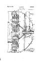
Fig. 1 is a longitudinal section through the 65 cowling and spinner on the line 11 of Fig.
3, with the engine cylinders indicated in outside view.
Fig. 2 is a front elevation of the engine in section through the fixed part of the cowl on line 22 in Fig. 1.
Fig. 3 is-a front elevation of the assembled cowl propeller.
Referring first to Fig. 1, 1O desi nates the engine crankcase and 12 the cylin ers thereon, the intercylinder spaces being blanked off by bellies 14 and 16 adapted to restrict the air flow to the finned periphery of the engine cylinders and thus reduce the total volume of air required; The crankshaft of the engine 7 projects at 18 in the usual way and is equipped with a standard-propeller hub 20 having standard propeller blades 22, it being an object of this invention ,to equip existing engines without change to the propeller or 7 other parts.
The propeller hub nut 24, however, may be lengthened in order to accommodate an additional nut 26 by which the blower vane hub 28 may be pinched onto the propeller hub. It will be seen that this blower vane hub 28 is cut out on two opposite sides to pass the propeller blade bosses of the propeller hub. To reinforce the blower vane hub 28 a plate 30 having an external flange 32 fitted over a pilot turned on the blower vane hub 28 is provided, the plate 30 being piloted on the propeller hub at 34c to maintain the parts in concentric relation. A second plate 36 is secured to the plate 32 and provided with a pair of 2&1111838 located substantially behind the propeller blades 22 and these arms or spokes extend to the periphery of the spinner shell 40 whereat the arms are provided with arcuate extensions 42 which are bolted to the spinner to form a demountable reinforcing bridge closing the end of the slots 44 which must be cut in the spinner 40 to permit assembly of the propeller. It should be noted that the arms or spokes 38 and their arcuate ends 42 100 reinforce the spinner against both radial and circumferential loads. It will be seen that the spinner 40 is inwardly beaded at 46 to define an axial air inlet.
The blower vane hub 28 is provided with a plurality of helically disposed ribs 48, to
which are riveted the. inner ends of a plurality of pitched blower vanes 50. These vanes are provided with flanges 52 at their outer ends, accurately conformed to the desired streamline contour of the spinner shell 40, to which these flanges 52 are firmly secured by riveting.
Preferably the vanes are first riveted to the helical ribs 48 and'then the hub 28 is located on a jig having an accurate arcuatecontour over which the flanging operation 52 may be done on each blade in succession and to insure the uniformity essential for true running of the spinner.
The best pitch angle for the vanes 50 depends upon the relative air velocity and, theo-.
' themselves is at retically, they will be more nearly parallel to the axis of rotation for the best results in a flight cowl andwill have a greater helix angle in a cowling for ground testing. Experiments to date, however, indicate that a compromise angle may be found which will give satisfactory results in both conditions.
In actual service a compromise in favor of the flight condition is'best because it is advantageous that the cooling on the ground should be less effective to assist in quick warming up of the engine. An angle somewhat steeper,
than the pitch angleof the propeller blades present indicated as most de sirable.
It will now be seen that by the construction here provided, the spinner is reinforced against centrifugal stresses with a minimum of obstruction to the air flow and that a construction is provided whereby great accuracy and rigiditv are given to the surface of the spinner. This is important because a slight wabble in the'spinner is very noticeable in operation. causing a very bad appearance and being apt to upset the balance which must be accurately maintained.
provides a" streamline engine nose and the fixed cowl may be suitably reinforced. at its front -end as bythe bead 64 and angle ring 66.
Although the drawings illustrate this invention on an air-cooled engine, it should be understood that itmay be applied to any cooling means. For example: a radiator for a with the propeller.
streamline nose to said cowling having an axial air entrance opening, a vane hub secured to the propeller, and a plurality of blower vanes each secured to said hub and to said shell to reinforce the blower. I
2. The combination with an engine-driven ropeller, of a truncated conical shell slotted or assembly about said propeller, and an armed member mounted on the'hub of the propeller and having arcuate ends secured to the shell to bridge said slots.
3. The combination: withanaircraft engine propeller, of a cooling air blower comprising an open-ended spinner shell having slots through which the blades of the propellerproject, bridge pieces reinforcing the otherwise open end of said slots, and arms on the bridge pieces extending to the hub of the propeller.
4. In apparatus of the class described, in combination, an open-ended conical shell having helical slots at its larger diameter,
a propeller having blades extending through said slots, a vane hub secured to the propeller, and vanes secured to said hub and to said shell.
5. In apparatus of the class described, in combination, an open-ended conical shell having helical slots towards its larger diameter, a propeller having blades extending through-the said slots, 9. vane hub secured to the propeller, vanes secured to said hub and to said shell, and a radial armed member secured to the hub and having reinforcing bridges secured across .the' otherwise open ends of said slots.
- 6. The combination with an aircraft enpropeller, means to reinforce the slotted end 7 of said vane hub, and blower vanes secured to said hub.
7. The combination with an aircraft en-' 'gine propeller, of a vane hub slotted to accommodate the roots of the blades of said propeller, means to reinforce the slotted'end of said vane hub, blower vanes secured to said hub, and means to secure said hub coaxially 8. The combination with an aircraft engine propeller, of a vane hub slotted to accommodate the roots of the blades of said r0- peller; means to reinforce the slotted en of said vane hub, blower vanes secured to said hub, means to secure said hub coaxially with iis the propeller, and a shell secured to the outer ends of said vanes and having slots through which the blades of said propeller project.
5 suitable cooling liquid may be disposed with- 9. The combination with, an aircraft en- 13o gine propeller, of a vane hub slotted to accomniodate the roots of the blades of said propeller, means to reinforce the slotted end of said vane hub, blower vanes secured to said hub, means to secure said bub coaxially with the propeller, a shell secured to the outer ends of said vanes and having slots through which the blades of said propeller p10 ect, and radial arms extending said reinforcing means and secured to the shell across the slots. 1
10, As a unit structi'ire, a detacliablespinner for an aircraft propeller including a spinner hub adapt-ed to embrace the propeller hub, an outer slielltlirongli which the propeller blades extend, and vanes extending from one to the other of and fastened to said spinner hub and shell.
11. A spinner for an aircraft propeller including a spinner hub, an enter siiell having slots formed therein through the propeller'blades extend, means extending redially out from said hub to reinforce said shell in the vicinity of said slots, abd vanes extending from one to the other of and fastened to said hub and shell; N
12, A spinner for an aircraft propeller including a spinner bnb, enter email through which the propeller blades extend, and blower vanes pitcliedat a steeper angle than the pitcb angle of the propeller blades extendmg from one to the other of said spinner parts, said vanes, hub and outer shell bein bodily removable as a unit. 13. A spinner for an aircraft propeller including a spinner hub, an'outer shell provided at its forward end with "an air inlet opening, and blower vanes extending radiali 1y out from said hub and fastened to said shell behind said opening, said bub, shell and v blower vanes being. adapted for attachment to and removal from said propeller as a unit.
14. The combination with an engine driven aircraft propeller of a unitary freely detachextending inwardly from said shell, and
'means at the inner ends of said vanes for tacbed to and to enclose the hub of sold a propeller, and blower vanes attached to and extending outwardly from said bub.
1'2. The combination with an engine driven aircraft propeller of a unitary freely detachable cooling blower comprisinga substantially streamline hub adapted to be at-: tached to and to enclose the hub of saidpropeller, blower vanes attached to and extending outwerdly from said hub, and e circular @l'lCtOSllIlg shell attached to the enter ends of said vanes, said hub ai -id said shell having openings termed therein for the pessa of the propeller blades theretbrougb, and said vanes lying substantially in the plane of the blades of said propellern In testimony whereof I hereunto a my signature RQLAND GHILTGNO joining said vanes and for attaching said blower to the hub of said propeller.
15; The combination with an en ine drivon air craft ropeller of a unitary eely detachable coo ingair blower comprising an outer circular shell, blower vanes attached to and extending inwardly from said shell,
and means at the inner ends of said vanes for joining said vanesand for attachin -said blower to the hub of said propeller said shell and said means having openings or receiving the blades of said propeller.-
' 16. The combination with an engine driv en'aircraft ropeller of a unitary freely de-e ,tachable co ing air blower comprising a substantially streamline-hub adapted to at- Eli)
Priority Applications (1)
| Application Number | Priority Date | Filing Date | Title |
|---|---|---|---|
| US539026A US1908820A (en) | 1931-05-21 | 1931-05-21 | Engine cowling |
Applications Claiming Priority (1)
| Application Number | Priority Date | Filing Date | Title |
|---|---|---|---|
| US539026A US1908820A (en) | 1931-05-21 | 1931-05-21 | Engine cowling |
Publications (1)
| Publication Number | Publication Date |
|---|---|
| US1908820A true US1908820A (en) | 1933-05-16 |
Family
ID=24149443
Family Applications (1)
| Application Number | Title | Priority Date | Filing Date |
|---|---|---|---|
| US539026A Expired - Lifetime US1908820A (en) | 1931-05-21 | 1931-05-21 | Engine cowling |
Country Status (1)
| Country | Link |
|---|---|
| US (1) | US1908820A (en) |
Cited By (3)
| Publication number | Priority date | Publication date | Assignee | Title |
|---|---|---|---|---|
| US2529103A (en) * | 1946-02-13 | 1950-11-07 | Curtiss Wright Corp | Spinner deicing system |
| US2607430A (en) * | 1946-02-26 | 1952-08-19 | Curtiss Wright Corp | Fan for aircraft propeller spinners |
| US3228476A (en) * | 1964-03-09 | 1966-01-11 | Charles B Brown | Aircraft spinner assembly |
-
1931
- 1931-05-21 US US539026A patent/US1908820A/en not_active Expired - Lifetime
Cited By (3)
| Publication number | Priority date | Publication date | Assignee | Title |
|---|---|---|---|---|
| US2529103A (en) * | 1946-02-13 | 1950-11-07 | Curtiss Wright Corp | Spinner deicing system |
| US2607430A (en) * | 1946-02-26 | 1952-08-19 | Curtiss Wright Corp | Fan for aircraft propeller spinners |
| US3228476A (en) * | 1964-03-09 | 1966-01-11 | Charles B Brown | Aircraft spinner assembly |
Similar Documents
| Publication | Publication Date | Title |
|---|---|---|
| RU2478806C2 (en) | Fan for turbo-machine of airborne vehicle, and turbo-machine of airborne vehicle, which contains such fan | |
| US2330622A (en) | Guiding and controlling device for cowlings | |
| US4046488A (en) | Radiator cooling fan | |
| US1427872A (en) | Airplane-radiator mounting | |
| US1908820A (en) | Engine cowling | |
| RU2099247C1 (en) | Device for compensation of reaction torque of main rotor of rotary-wing flying vehicle | |
| US2270912A (en) | Cowling for aircraft | |
| US1946571A (en) | Propeller with auxiliary blades applicable to driving aircraft | |
| US2426635A (en) | Engine, propeller, and fan drive | |
| US2329606A (en) | Propeller fairing | |
| US2535527A (en) | Model airplane propeller | |
| US2173896A (en) | Blower cooling means for air cooled engines | |
| US2125187A (en) | Propeller | |
| US1896222A (en) | Engine cowling | |
| US1990979A (en) | Engine cooling means | |
| US2145131A (en) | Means for directing engine cooling air | |
| US1650464A (en) | Aeronautical propeller | |
| US2637403A (en) | Propeller spinner construction with boundary layer control | |
| GB518873A (en) | Improvements relating to spinners and like fairings for airscrews | |
| US1742938A (en) | Propeller for aircraft | |
| US1880997A (en) | Airplane | |
| US1922825A (en) | Airplane | |
| US2612229A (en) | Variable pitch propeller blade root construction | |
| US2529103A (en) | Spinner deicing system | |
| GB383792A (en) | Improvements in or relating to the cooling and cowling of aircraft or other propeller driving engines |