US1908720A - Railway car - Google Patents
Railway car Download PDFInfo
- Publication number
- US1908720A US1908720A US404964A US40496429A US1908720A US 1908720 A US1908720 A US 1908720A US 404964 A US404964 A US 404964A US 40496429 A US40496429 A US 40496429A US 1908720 A US1908720 A US 1908720A
- Authority
- US
- United States
- Prior art keywords
- doors
- car
- members
- portions
- adjacent
- Prior art date
- Legal status (The legal status is an assumption and is not a legal conclusion. Google has not performed a legal analysis and makes no representation as to the accuracy of the status listed.)
- Expired - Lifetime
Links
- 238000010276 construction Methods 0.000 description 14
- 239000002184 metal Substances 0.000 description 10
- 230000003014 reinforcing effect Effects 0.000 description 7
- 230000000875 corresponding effect Effects 0.000 description 4
- RYGMFSIKBFXOCR-UHFFFAOYSA-N Copper Chemical compound [Cu] RYGMFSIKBFXOCR-UHFFFAOYSA-N 0.000 description 3
- 230000007246 mechanism Effects 0.000 description 3
- 239000011324 bead Substances 0.000 description 2
- 238000005266 casting Methods 0.000 description 2
- 241001474033 Acar Species 0.000 description 1
- 235000007575 Calluna vulgaris Nutrition 0.000 description 1
- 240000002804 Calluna vulgaris Species 0.000 description 1
- 229910001208 Crucible steel Inorganic materials 0.000 description 1
- 230000003247 decreasing effect Effects 0.000 description 1
- 230000008030 elimination Effects 0.000 description 1
- 238000003379 elimination reaction Methods 0.000 description 1
- 239000000945 filler Substances 0.000 description 1
- 230000000284 resting effect Effects 0.000 description 1
Images


Classifications
-
- B—PERFORMING OPERATIONS; TRANSPORTING
- B61—RAILWAYS
- B61D—BODY DETAILS OR KINDS OF RAILWAY VEHICLES
- B61D9/00—Tipping wagons
Definitions
- a primary object of the invention is to provide the car with lading discharge openings of maximum size.
- Another object of the invention is to provide the car with a floor formed substann tially entirely of cast metal parts whereby a more durable and rigid iloor construction is produced, By forming the floor with cast steel parts or sections a more economical construction and one whichv may be more quickly assembled is produced due to the elimination of many of the rivets employed in floors of sheet metal construction.
- a primary feature of the invention consists in providing the car with a substantially rectangular ioor unit involving a plurality of doors hingedly connected to the car center sill and respectively disposed on opposite sides thereof, the hinged edges of the doers being disposed in overlapping re" lation.
- a further feature of the invention resides in providing a substantially rectangular floor unit involving two pairs of doors hingedly connected to the car center sill, one door of each pair being disposed on opposite sides of the center sill and respectively hav- 'ing portions overlapping the other door of its pair and the adjoiningdoor of the other pair.
- hiet-her feature of the invention consists in providing a transverse underframe member with a substantially horizontally disposed flange spaced abovethe top of the center sill and forming a portion of the car floor.
- a further feature of the invention resides in providing the car with angle shaped members adapted to be disposed between the car upwardly projecting extensions respectively having portions disposed in planes normal to the longitudinal aXis of the car to which car side stakes may be secured, said portions being fashioned with rigidifying flanges.
- a still further feature of the invention consists in associating with the top flanges of the underframe members a plurality of hingedly mounted doors adapted tospan the spaces between the flanges, the hinge axes of the doors extending longitudinally of the car and being coincident.
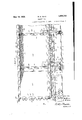
- Figure l is a top view of a portion of the car, partly in elevation and partly in section.
- Figure 2 is a longitudinal sectional view talren on line 2 2, Figure 1.
- Figure 3 is a plan view of one of the door units and the portions ofthe car adjacent thereto.
- Figure 5 is a sectional view taken on line 5 5, Figure 4.
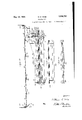
- Figure 6 is a fragmentary side view of the car, portions of the car side being broken away.
- Figure 8 is a transverse sectional view adjacent the center of the car, the doors being in elevation and the adjacent portions of the underframe member being omitted.
- Figure 9 is a sectional view taken on line 9-9, Figure 4.
- Figure 10 is a fragmentary plan view showing the doors in disassociated positions.
- Figure 12 is a sectional view taken on line 12-12, Figure 4.
- Figure 14 is a fragmentary sectional view taken on line lil-14, Figure 1.
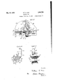
- Figure 15 is a plan view of one of the angle members.
- Figure 17 is a fragmentary transverse sectional view of the car showing one of the transverse underframe members in side elevation and omitting the doors and their hinge brackets.
- Figure 20 is a fragmentary side elevational view of the end construction of the underframe member illustrated in Figure 18.
- Figure 21 is-an end elevational view of the construction illustrated in Figure 20..
- FIG. 1 indicates the box-like center sill having two beam members 2, each of which is provided with a web 3 and top and bottom Vflanges el and 5, respectively, the top lianges being 'preferably connected by a top cover plate 6.
- the car interposed between the beam members adjacent the body holsters of the car, to be hereinafter described, are the usual center castings or filler members 7. ylhe side sills of 4.51.? the car which are designated by the reference numeral 8 are of a modified Z-shape having upper and lower substantially vertically disposed flanges 9 and 10, respectively, connected by an inclined web 11. The center sill and sidesills are rigidly connected by the underframe members 12 and 13, 12 indicating the body bolster and 13 the cross bearers.
- the bolster Adjacent its central portion the bolster is provided with substantially vertical flanges 20 which are rigidly secured to opposite sides of the center sill by rivets 21 passing through the webs 3 of the cenler beams. At its opposite ends the bolster is integrally formed with walls or flanges having relatively oli'set portions 23 and 24 adapted to be respectively secured to the flanges 9 and 10 of the side sills and with an inclined portion 25 adapted to be secured to the web 11 thereof.
- the bolster instead of constructing the bolster as an integral casting it may advantageously be cast in two similarly formed sections which may be conveniently connected by angle shaped splice platos 26 overlappingly secured by rivets 27 to opposite faces ofthe web portionswhich overlie the center sill and by rivets 2 8 to the und-ersidcs of the top plate members or flanges 14.
- the bolster Vsections may be conveniently connected by a strap or plate 29 which pas-ses under the center sill and is secured to the bottom plate members or flanges 15 by rivetsSO.
- the holsters are preferably formed with extensions 3l which pro ject above the top flanges 14 thereof.
- Each of the extensions is formed with a flange 33 which constitutes a continuation of the end wall or flange of the bolster and with a portion Srl disposed substantially in the plane of the central web 16 thereof to which the side stakes may be secured by rivets 35.
- the extensions may be stiffened or reinforced by flanges 86 of gradually decreasing width and which are disposed in substantially the plane of and constitute continuations of the truss flanges 17 acent the ends of the holsters.
- the car side stakes may advantageously be of modified bulb angle shape having flanges ll() and 41, the latter being the one selfll cured to the upwardly projecting extensions 3l of the underframe members.
- rlhe flanges 40 afford convenient means to which the side sheets 42 of the car may be attached.
- the side sheets are also overlappingly secured to the upper vertical flanges 9 of the side sills and the flanges 23 and 33 of the uuderframe members.
- the side sheets incline upwardly and inwardly, as at d3, and terminate in substantially vertically disposed flanges i4 secured to the depending legs 45 of the angle shaped side top rails flS.
- the end side sheets 49 converge inwardly from adjacent the body holsters to the car ends, being rigidly secured the latter points to the corner posts 50.
- corner posts are preferably of angle shape having legs 5l to which the end side sheets are secured and legs 52 to which corrugated end sheets 53 are secured. At their upper edges the end sheets are secured to the end top rails 5d which are attached to the side top rails by angle brackets 55.
- rllhe angle member 56 has one leg which rests npon and is secured to the top fla ages f sill and another leg which is secured to the lower edge of the end sheet.
- the angle member 57 has one leg which is also secured to the end sheet above the point to which the angle member 56 is secured and another leg disposed in substantially the same horizontal plane as the top plate members or iiangcs the center ld of the transverse underfranie members.
- a substantially rectangular i'ioor unit comprising a plurality of doors which are hingedly connected to the car adjacent the center sill having their free edges disposed adjacent the car sides.
- a substantially rectangular i'ioor unit comprising a plurality of doors which are hingedly connected to the car adjacent the center sill having their free edges disposed adjacent the car sides.
- the floor unit between adjacent und-erframe members comprises two pairs of hinged doors, one door of each pair being Vdisposed on opposite sides of the center sill.-
- the doors of one pair are designated by the letters A and B and the doors of the other pair by the letters C and D.
- the doors and B and the doors C and D have been considered as respectively constituting pairs it will, of course, be .appreciated that the doors A and C and the doors B and D may likewise be considered as respectively constituting pairs.
- the doors A and D are'identical and as B and C are also identical, for a purpose to lbe hereinafter described, corresponding parts of the doors A and D will be designated by similar reference numerals as also will the corresponding parts of the doors B and C.
- each door is preferably reinforced by rectangularly arranged flanges disposed slightly inwardly of the mar- ⁇ @final edges of the plate portion thereof.
- Each door may be also reinforced by flanges G0 which converge from adjacent the corners at its hinged edge and intersect inwardly of its free. edge.
- flange 6l substantially normal to its hinge axis which affords convenient means to which a portion of the door supporting mechanism. to be hereinafter described, may be secured.
- the doors B and C Adjacent their hinged edges the doors B and C are fashioned with downwardly offset portions 62 adapted to be overlapped by adjacent portions 63 of the doors A and D Y respectively.
- the upper surfaces ofthe offsets 62 may be conveniently evlindrically curved.. the axes of curvature being coincident with the pivotal axes of the doors.
- the portions 63 of the doors may advantageously be reinforced by a plurality of ribs or flanges 64 which-are connected to the adjacent flange 59.
- the doors In order to pivotally connect the doors to the car body they are provided with a plurality of apertured lugs, the lugs of the doors A and D being designated by the reference numeral and thoseof B and C by the reference numeral 66.
- the doors are so proportioned and their hinge lugs arranged in such a manner that they preferably have a common hinge aXis which extends longitudinally of the car. 'Ihe lugs of each door are integrally connected to the plate portion thereof and the adjacent flange 59, but ⁇ in order to permit the offset portions 62 of the doors B and C to be overlapped by the portions 63 of the doors A'and D the lugs of the latter doors are spaced below their plate portions.
- bracket-s 67, 68 and ⁇ 69 Resting upon the top of the center sill and rigidly secured thereto are a plurality ot bracket-s 67, 68 and ⁇ 69 for respectively cooperating with the hinge lugs of the doors.
- the bracket 67 cooperates with the outer two hinge lugs on the doors A and B
- the bracket G8 cooperates with the outer hinge lugs on the doors C and D
- the bracket 69 cooperates with the inner hinge lugs of all of the doors.
- Each of the. brackets 67 and 68 is provided with upwardly projecting bosses 70 between which the cooperatinglugs of the doors are disposed, the bosses being provided with alined apertures for receiving hinge pins 71 adapted to entend through the apertures of the hinge lugs.
- the central bracket 69 is provided with upwardly projecting bosses 72, 73 and 7d, the inner lugs of the doors A and B being disposed between the bosses 7 2 and 78 and the inner lugs of the doers C and D being disposed between the bosses 73 and 74.-.
- those of the brackets 69 are also formed with alined apertures for receiving a hinge pin 75 which extends through corresponding apertures in the inner lugs of all of the doors;
- it 5 is preferred that the hinge lugs of the doors on one side of the car center sill alternate with the hinge lugs of the doors on the opposite side.
- Each of the doors A, B, C and D are fashioned with downwardly offset portions 8O adjacent their outer side marginal edges so as to underlie adjoining portions of the top flanges or plate members 14 of the adjacent under-frame members. Adjacent the hinged edges of the doors B and C the portions 80 thereof are further ofl'set downwardly, as at 81, so that these portions, in addition to underlying the top flanges of the adjacent underframe members, may also respectively underlie the adjacent portions of the doors A and D.
- angle members 82 Disposed between the free edges of the doors and the sides of the car and extending continuously between adjacent underframc members are angle members 82.
- Each of liese members is provided with a substantially vertically disposed leg 83 which may be secured to the upper flange 9 of the adjoining side sill by rivets employed for connecting the side sheets thereto and with a substantially horizontally disposed leg 84 which projects inwardly into the car, the upper surface of the latter being disposed in the same plane as the upper surfaces of the closed doors and the flanges 14 of the underframe uien'ibers.
- Adjacent their opposite ends each of the angle members is fashioned with offset portions 85 adapten to be overlappingly secured to the top flanges of the djacent ui'iderfraino members.
- the horizontal leg of the angle members may be advantageously reinforced' by flanges or ribs
- the free edges of the doors may be disposed in overlapping relation to the horizontal flanges 84 of the angle members they are each provided with downwardly olfset portions 87 adapted to underlie the latter.
- These offset portions 87 are disposed in the same planes as the offset portions of the doors which underlie the top flanges of the underframe members.
- the former are provided with further downwardly oli'set portions 87.
- the doors may be more easily cast and it is to be noted that the marginal flanges 59 are arranged at the point of juncture of the offset portions and the main body of the vplate-like portions of the doors so as to strengthen the doors at these points. Furthermore, the marginal flanges may be conveniently formed with rigidifying beads or ribs 88. From the manner in which the doors overlap each other and the adjacent members of the car it will be perceived that line lading is effectually prevented from accidentally escaping from the car.
- these spaces are preferably closed by a plurality of plate-like members 91.
- rlhe platelike members at the sides of the car respectively rest upon and are secured to adjacent portions of the top flange 14 of the body bol ster and the horizontal leg of the angle member 57 of the end sill.
- the upper surface of the main body portion of the plate members adjacent the sides of the car may be disposed in substantially the same plane as the upper surfaces of the doors and underframe members the portions secured to the latter are preferably offset upwardly as 91.
- each, with theexu ception of one of the side plates, is fashioned with a downwardly offset portion 94 to underlie the adjoining portion of the adjacent plate.
- each may be conveniently formed with a downwardly extending flange or rib 95.
- a center sill of two doors arranged onopposite sides of the latter and respectively having their free edges disposed adjacent opposite sides of the car, lugs on said doors for hingedly connecting them Vto the car, said doors having plate-like portions adjacent their hinge axes disposed in overlapping relation with each other, and reinforcing flanges on said doors adjacent their hinge lugs and substantially parallelto their hinge axes.
- the combination ywith a center sill, of two'hinged doors arranged a center sill, of a floor unit involving two pairs of hinged doors, the doors of each pair being disposed on opposite sides of the cen ter sill, the adjoining side edges of said pairs of doors being adapted to be disposed in overlapping relation and the hinged edges of the doors of each pair being also adapted to be disposed in overlapping relation.
- a railway car having two pairs of hinged doors comprising a substantially rectangular floor unit, one door of each pair having portions adapted to be respectively disposed in overlapping relation to the other door of its pair and to one of the doors of the other pair.
- the combination with a center sill, of a floor unit involving two pairs of hinged doors, the doors of each pair being disposed on opposite sides of the center sill, one door of each pair having portions adapted to respectively overlie portions of the other door of its pair and adjacent portions of the adjoining door of the other pair, the meeting edges of the overlying portions ofsaid doors being in planes forming oblique angles with the hinge axes of said doors.
- the combination with a center sill, of two pairs of hinged doors comprising a substantially rectangular floor unit, one door of each pair having portions respectively adapted to be disposed in overlapping relation to adjacent portions or the other door of said pair and adjacent portions of the adjoining door ofthe other pair, the portions of all of said doors which are adapted to be disposed in overlapping rela tion adjoining each other adjacent the central portion of said rectangular fioor unit and the adjoining edges of the said overlapping portions being disposed in planes forming oblique angles with the hinge axes of said doors.
- a center sill of two pairs of hinged doors comprising a substantially rectangular oor unit, the doors of each pair being disposed on opposite sides of the center sill, a plurality of brackets secured to the center sill, and hinge lugs formed 'on each of said doors adapted to be pivotally connected to said brackets, one lug of'each door ⁇ being pivotally connected to one of said brackets.
- the combination with a center sill, of' two pairs of hinged doors comprising a substantially rectangular floor unit, the doors of each pair being disposed on opposite sides of the center sill, three brackets rigidly secured to said center sill, a plurality of lugs formed on each of said doors adapted to receive means for pivotally con necting the lat-ter Vto the brackets, one lugot each door being pivotally connected to the central one of said brackets and the other lugs of each pair of doors being respectively pivotally connecter. to the other brackets.
- a railway car having a plurality Vot hinged doors comprising asubstantially rectangular door unit, each of said doors being fashioned with va reinforcing iiange substantially normal to its hinge axis and with portions extending beyond said reinforcing flange, the said portions of the doors being adapted to be disposed in overlapping relation.
- each of said floor units comprising a plurality of doors hingedly ⁇ connected to the car adjacent the center thereof, and having platelike portions adjacent their hinged edges disposed in' overlapping relation.
- a fiat bottom gondola car the combinationwith a plurality of transverse underframe members respectively provided with substantially horizontally disposed top flanges forming portions of the car fioor, of a. plurality of hinged doors comprising a substantially'rectangular fioor unit disposed between said un'derframe members, each of said doors having a. top plate-like portion, the vside marginal edges of the floor units and adj oining portions of the top flanges of the underframe members being disposed in overlapping relation and the plate-like portions of the doors being'disposed in overlapping re- A lation with each other adjacent the hinge axes of the doors.
- a 'flat betteln gondola car the combination with a plurality of transverse underframe members respectively provided with substantially horizontally disposed top anges 'forming portions of the car floor, of a substantially rectangular fioor unit disposed between each ofthe said underframe members, the side marginaledgesof the floor unit being offset to underlie adjoining portions of the top flanges of adjacent underframe members ⁇ and at least one door of the unit being offset adjacent its hinge axis to 'underlie the portion adj acent the hinge axis of an adjoining door.
- a flat bottom gondola car the combination with a center sill, of a plurality of transferse underframe members respectively provided with substantially horizontally di "posed top flanges vforming portions of the car lloor, and a substantially rectangular lloor unit disposed between each of said underframe members and cooperable with the top flanges thereof, each of said floor units comprising two pairs of hinged doors, the doors oil each pair being disposed on opposite sides of the center sill and having portions adapted to be disposed in overlapping relation.
- each of said floor units comprising two pairs of hinged doors, the doors of each pair being disposed on opposides of the center sill and respectively having portions adapted to be disposed in overlapping relation tothe adjoining doors of the other pair.
- a flat bottom gondola car the combination with a center sill, of a plurality of transverse underframe members respectivelj provided with substantially horizontally disposed top flanges forming portions of 'the car rfloor, and a substantially rectangular floor unit disposed between each of said underirame members and cooper-able with the top flanges thereof, each of said floor units comprising two pairs of hinged doors, the doors of each pair being disposed on opposite sides oit the center sill, one door of each pair having portions adapted to overlap adjacent portions of the other door of its pair and adjacent portions of the adjoining door of the other pair.
- each oi said floor units compri sing two pairs of hinged doors, the doors of each pair being disposed on opposite sides et the center sill and having their free edges disposed adjacent opposite sides of the car, the hinged edges of the doors on one side of the center sill being adapted to be disposed in overlapping relation to the hinged edges of the doors on the other side of the center sill.
- each of said floor units comprising two pairs of hinged doors, the hinge axes of the doors oi both pairs being coincident and the hinged edoe of one door of each pair being disposed in overlapping relation to the hinged edge of the other door of its pair.
- each of' said plate-like members being provided with an oflset portion adapted to be overlapped by the adjoining portion ot the adjacent plate member and being also provided with a ri,1 flange adjacent the oliset thereof.
- a flat bottom gondola car the combination with a center sill, a plurality of transverse under-frame memberscrespo@ tively provided with substantially horizontal top flanges spaced above the center sill and forming portions of the car floor, a plurality of doors spanning the space the top flanges of adjacent underiirame members and hingedly connected to the car adjacent its longitudinal axis, said doors when in closed positions being dispos fl in horiz/:ontal planes above the center sill, and inembers interposed between 'free edges of the doors and the car sides, each of said members being ⁇ secured to adjacent underl rame members.
- each of said underi'rame members having a substantially horizontally disposed ⁇ top flange spaced above the center sill and forming a portion of the car floor, substantially rectangular licor units respectively disposed between 'the underi'rame members in a plane above the center sill, each of said floor units comprising a plurality of doors hingedly connected to the center sill and cooperating with the top flanges of adjacent underirame members, the free edges oi said doors being disposed adj acent the car sides, and angle-shaped mem.- bers interposed bet veen the free edges of the door and car sides, said members being respectively secured to the adjacent side sill and undertrame members and each being provided with a substantially horizontal flange for overlappingly cooperating With the tree edge of an adjacent
- 35. ln a. flat bottom gondola car the combination with a center sill and side sills, of a transverse underframe member having portions rigidly secured to the center sill and side sills and provided with top and bottom plate-like members, said plate members being connected by a longitudinally substantially centrally disposed web and a plurality oftransverse flanges, the opposite ends of said underfranie member being integrally formed with upwardly projecting extensions, each of said extensions having a portion disposed in a plane substantially parallel with the said longitudinal web and a rigidifying flange constituting a continuation of one of the said transverse flanges, the said portions of said extensions respectively aifording means to which car side stakes may be secured.
- a. transverse underframe member having portions rigidly secured to the center sill and side sills, said underframe member involving a top plate-like member constituting a portion of the car door, abottom plate-like member, said plate-like members being connected by a longitudinally extending substantially centrally disposed web and a plurality of transversely extending truss-like flanges, the opposite ends of said underframe member being integrally formed with portions projecting above said top plate-like member and disposed in substantially the same plane as said longitudinal web affording means to which car side stakes may be secured, each of said portions being provided with a ange disposed in a plane substantially parallel with the adjacent transversely extending flange.
- a railwayicar having a plurality of hinged doors for vclosing a lading discharge opening thereof, said Vdoors being arranged with their hingededges adjacent each other, one of said doors being provided'onitsy underside with a reinforcingliange substantially parallel with its hinge axis and having a plate portion projecting beyond the latter for overlapping the adjacent portionof the other vof saiddoors, said plate portion being provided with Vrigidifying ribs extending at an angle to and formed integrally with said flange.
- A' cast metall sectional floor for a iiat bottom gondola car including members 'con- .stituting integral portions of transverse underframe members of the car, ⁇ a plurality of hinged doors disposed between said members, and members extending longitudinally of the riccar intermediate the sides thereof and the portions of said doors adjacent the latter.
- a cast metal sectional licor forl a flat bottom gondola car including members constituting integral portions of transverse underframe members of the car, hinged doors disposed between said members, members secured to the car sides and respectively interposed between the latter and the portions of l the doors adjacent thereto, and plate-like members extending between the ends of the car and the underframe members adjacent thereto.
- a transverse underframe member rigidly secured to said sills andbeing integrally provided with a plate-like upper portion spaced above the center sill and forming a portion of the car Hoor, the outer ends of said member being integrally provided with extensions proj ect-ing upwardly within the car affording means for the attachment of car side stakes.
- a transverse underframe member comprising two cast metal sections respectively disposed on opposite sides of the center sill and respectively secured to the latter and to the side sills, each of said sections being provided with a plate-like portion spaced above the center sill and forming a portion of the car floor, the inner ends of said plate-like portions respectively terminating adjacent the longitudinal axis of the car, and means disposed above the center sill- Jfor rigidly connecting said plate-like portions.
Landscapes
- Engineering & Computer Science (AREA)
- Transportation (AREA)
- Mechanical Engineering (AREA)
- Body Structure For Vehicles (AREA)
Description
May 16, 1933.
-' w. E. WINE RAILWAY CAR Original Filed Nov. 5, 1929 8 Sheets-Sheet 2 w. E. WINE RMLWAY CAR May 16, 1%33.
8 Sheets-Sheet 3 Original Filed Nov. 5, `1929 PIIIII May 16, 1933. w. E. WINE RAILWAY CAR original Filed Nov. 5, 1929 8 Sheets-Sheet 4 vir. E. WINE RAILWAY CAR May 16, 1933.
Original Filed Nov. 5, 1929 8 Sheets-Sheet 5' W. E. WINE RAILWAY CAR May 16, 1933.
Original Filed Nov. 5, 1929 8 Sheets-Sheet 6 W. E. `WINE RAILWAY CAR May 16, 1933.
original Filed Nov. 5, 1929 8 Sheets-Sheet '7 May 16, 1933. w. E, MNE 1,908,720
RA I LWAY C AR 8 Sheets-Sheet 8 Original Filed Nov. 5, 1929 Patented May 16, 1933 NETE@ STATES WILLIAvI E. WINE, OF TOLEDO, OHIO i RAILWAY GAB.
Application filed November 5, i929, Serial No. 404,964. Renewed May 11, 1932. y
My invention relates to railway cars and more particularly to cars of the flat bottom gondola type.
A primary object of the invention is to provide the car with lading discharge openings of maximum size.
Another object of the invention is to so construct the underframe members of the car that portions thereof constitute parts or sections of the car floor.
Another object of the invention is to provide the car with a floor formed substann tially entirely of cast metal parts whereby a more durable and rigid iloor construction is produced, By forming the floor with cast steel parts or sections a more economical construction and one whichv may be more quickly assembled is produced due to the elimination of many of the rivets employed in floors of sheet metal construction.
A primary feature of the invention consists in providing the car with a substantially rectangular ioor unit involving a plurality of doors hingedly connected to the car center sill and respectively disposed on opposite sides thereof, the hinged edges of the doers being disposed in overlapping re" lation.
A further feature of the invention resides in providing a substantially rectangular floor unit involving two pairs of doors hingedly connected to the car center sill, one door of each pair being disposed on opposite sides of the center sill and respectively hav- 'ing portions overlapping the other door of its pair and the adjoiningdoor of the other pair.
hiet-her feature of the invention consists in providing a transverse underframe member with a substantially horizontally disposed flange spaced abovethe top of the center sill and forming a portion of the car floor.
A further feature of the invention resides in providing the car with angle shaped members adapted to be disposed between the car upwardly projecting extensions respectively having portions disposed in planes normal to the longitudinal aXis of the car to which car side stakes may be secured, said portions being fashioned with rigidifying flanges. i
A still further feature of the invention consists in associating with the top flanges of the underframe members a plurality of hingedly mounted doors adapted tospan the spaces between the flanges, the hinge axes of the doors extending longitudinally of the car and being coincident. j
Other and more specific features of the invention residing in advantageous forms and combinations and relation of parts will hereinafter appear and be claims.
In the drawings illustrating a preferred embodiment of the invention:
Figure l is a top view of a portion of the car, partly in elevation and partly in section.
Figure 2 is a longitudinal sectional view talren on line 2 2, Figure 1.
Figure 3 is a plan view of one of the door units and the portions ofthe car adjacent thereto.
Figure 4 is an enlarged detailed view of the doors adjacent the center of the car. Y Y
Figure 5 is a sectional view taken on line 5 5, Figure 4.
Figure 6 is a fragmentary side view of the car, portions of the car side being broken away. Y
Figure 7 is a sectional view taken on line 7-?, Figure 3.
Figure 8 is a transverse sectional view adjacent the center of the car, the doors being in elevation and the adjacent portions of the underframe member being omitted.
Figure 9 is a sectional view taken on line 9-9, Figure 4.
Figure 10 is a fragmentary plan view showing the doors in disassociated positions.
Figure 11 is a fragmentary perspective View of the inner edges of the doors adjacent the sides of the car.
Figure 12 is a sectional view taken on line 12-12, Figure 4.
pointed out in the Figure 13 is a fragmentary sectional view taken on line 13-13, Figure 1.
Figure 14 is a fragmentary sectional view taken on line lil-14, Figure 1.
Figure 15 is a plan view of one of the angle members.
Figure 16 is a side elevational view of the construction `illustrated in, Figure 15.
Figure 17 is a fragmentary transverse sectional view of the car showing one of the transverse underframe members in side elevation and omitting the doors and their hinge brackets.
Figure 18 is atransverse sectional View of the car illustrating another of the transverse underframe members of the' car and also omitting the doors and their hinge brackets. Figure 19 is a fragmentary sectional View taken on line 19-.19, Figure 18.
Figure 20 is a fragmentary side elevational view of the end construction of the underframe member illustrated in Figure 18.
Figure 21 is-an end elevational view of the construction illustrated in Figure 20..
Inasmuch as the construction of the end portions of the car is the same and since, between these end portions, the car may be conn sidered as being made up of a plurality of identical sections, each section being defined by vertical planes passing through adjacent underframe members,onlyenough of the car has been illustrated in the drawings to in-Y clude two of the underframc members and the adjacent end ofthe car.l
Referring more particularly to the drawings 1 indicates the box-like center sill having two beam members 2, each of which is provided with a web 3 and top and bottom Vflanges el and 5, respectively, the top lianges being 'preferably connected by a top cover plate 6.
interposed between the beam members adjacent the body holsters of the car, to be hereinafter described, are the usual center castings or filler members 7. ylhe side sills of 4.51.? the car which are designated by the reference numeral 8 are of a modified Z-shape having upper and lower substantially vertically disposed flanges 9 and 10, respectively, connected by an inclined web 11. The center sill and sidesills are rigidly connected by the underframe members 12 and 13, 12 indicating the body bolster and 13 the cross bearers.
Each of the body holsters comprises top and bottom plate-like members or flanges 14 and 15, respectively, the former being spaced above the top of the center sill and constituting a portion of the lioor of the car. These plate-like members are connected by a longitudinally extending substantially centrally disposed web portion 16 and by transversely extending truss-like portions or flanges 17. The web portions may be surL ably apertured, as at 18, so as to reduce the weightV of the holsters, the portions of the web bounding the openings or apertures being fashioned with rigidifying beads or ribs 19. Adjacent its central portion the bolster is provided with substantially vertical flanges 20 which are rigidly secured to opposite sides of the center sill by rivets 21 passing through the webs 3 of the cenler beams. At its opposite ends the bolster is integrally formed with walls or flanges having relatively oli'set portions 23 and 24 adapted to be respectively secured to the flanges 9 and 10 of the side sills and with an inclined portion 25 adapted to be secured to the web 11 thereof.
instead of constructing the bolster as an integral casting it may advantageously be cast in two similarly formed sections which may be conveniently connected by angle shaped splice platos 26 overlappingly secured by rivets 27 to opposite faces ofthe web portionswhich overlie the center sill and by rivets 2 8 to the und-ersidcs of the top plate members or flanges 14. At their lower portions the bolster Vsections may be conveniently connected by a strap or plate 29 which pas-ses under the center sill and is secured to the bottom plate members or flanges 15 by rivetsSO. Thus it will be seen that the body holsters while made in two sections are of such construction that they may be rigidly and firmly connected to adjoining portions of the carunderframe.
-To brace the ear sides and to afford convenient means to which inside side stakes 32 may be rigidlyv secured the holsters are preferably formed with extensions 3l which pro ject above the top flanges 14 thereof. Each of the extensions is formed with a flange 33 which constitutes a continuation of the end wall or flange of the bolster and with a portion Srl disposed substantially in the plane of the central web 16 thereof to which the side stakes may be secured by rivets 35. The extensions may be stiffened or reinforced by flanges 86 of gradually decreasing width and which are disposed in substantially the plane of and constitute continuations of the truss flanges 17 acent the ends of the holsters.
As the cross bearers 13 are in all major respects of substantially the same construction as the body holsters, the same reference numerals are used to designate correspond ing parts of these two underframe members. However, since the cross bearers do not cooperate with the car trucks (not shown) they are, of course, not provided, as are the bolsters. with horizontal portions 37 to which sido bearing wear plates 38 may be secured. Furthermore Ythe sections of the cross bearer instead of being connected at their lower portions by a strap similar to that employed for connecting the bony bolster sections are connected by a T-shaped member 39,
The car side stakes may advantageously be of modified bulb angle shape having flanges ll() and 41, the latter being the one selfll cured to the upwardly projecting extensions 3l of the underframe members. rlhe flanges 40 afford convenient means to which the side sheets 42 of the car may be attached, At their lower edges the side sheets are also overlappingly secured to the upper vertical flanges 9 of the side sills and the flanges 23 and 33 of the uuderframe members. At their upper edges the side sheets incline upwardly and inwardly, as at d3, and terminate in substantially vertically disposed flanges i4 secured to the depending legs 45 of the angle shaped side top rails flS. The other leg i7 of each of the side top rails projects outwardly, and overlies the inclined portions 43 of the side sheets, terminating in substantially the plane of the body portions of the side sheets. Any suitable bracket members 4S may be employed for rigidifying this top construction of the car, the brackets beingsecurcd to the inclined portions of the side sheets, the. upper portions of the side stakes and the top rails.
In order that safety appliances such as ladders (not shown) may be secured to the sides of the car adjacent the ends thereof the end side sheets 49 converge inwardly from adjacent the body holsters to the car ends, being rigidly secured the latter points to the corner posts 50. rlhe corner posts are preferably of angle shape having legs 5l to which the end side sheets are secured and legs 52 to which corrugated end sheets 53 are secured. At their upper edges the end sheets are secured to the end top rails 5d which are attached to the side top rails by angle brackets 55.
Secured to the lower portions of the end sheets 5st are angle members and 57 wl zch. together with the lower portion of the end sheets, constitute the end sills of the car. rllhe angle member 56 has one leg which rests npon and is secured to the top fla ages f sill and another leg which is secured to the lower edge of the end sheet. The angle member 57 has one leg which is also secured to the end sheet above the point to which the angle member 56 is secured and another leg disposed in substantially the same horizontal plane as the top plate members or iiangcs the center ld of the transverse underfranie members.
gitudinal underframe members, the side stakes and the side and end sheets are secured together ina manner to produce a most rigid construction.
Disposed between each of underframe members is a substantially rectangular i'ioor unit comprising a plurality of doors which are hingedly connected to the car adjacent the center sill having their free edges disposed adjacent the car sides. As it is desirable to use cast metal doors on account of their durability and 'inherent rigidity, instead of employing one door on each side of the center sill to span or close the space between adjacent underframe members two doors are preferably employed because, should only one door be employed it would have to be of such size as to make it cumbersome and dicult to operate. rllhus, the floor unit between adjacent und-erframe members comprises two pairs of hinged doors, one door of each pair being Vdisposed on opposite sides of the center sill.- The doors of one pair are designated by the letters A and B and the doors of the other pair by the letters C and D. Although for purposes of description the doors and B and the doors C and D have been considered as respectively constituting pairs it will, of course, be .appreciated that the doors A and C and the doors B and D may likewise be considered as respectively constituting pairs. As the doors A and D are'identical and as B and C are also identical, for a purpose to lbe hereinafter described, corresponding parts of the doors A and D will be designated by similar reference numerals as also will the corresponding parts of the doors B and C.
All of the doors are provided with platelilre portions, the major part of the upper surfaces of which are, when the doors are in closed position, disposed in the same plane as the upper surfaces of the top plate or liange portions of the underframe members. Cn its underside each door is preferably reinforced by rectangularly arranged flanges disposed slightly inwardly of the mar- `@final edges of the plate portion thereof. Each door may be also reinforced by flanges G0 which converge from adjacent the corners at its hinged edge and intersect inwardly of its free. edge. Between the point of intersection of these flanges to the flange 59 at the free edge of the door the latter is formed with flange 6l substantially normal to its hinge axis which affords convenient means to which a portion of the door supporting mechanism. to be hereinafter described, may be secured.
Adjacent their hinged edges the doors B and C are fashioned with downwardly offset portions 62 adapted to be overlapped by adjacent portions 63 of the doors A and D Y respectively. In order that these overlapping portions will not interfere with free opening and closing of the doors, the upper surfaces ofthe offsets 62 may be conveniently evlindrically curved.. the axes of curvature being coincident with the pivotal axes of the doors. The portions 63 of the doors may advantageously be reinforced by a plurality of ribs or flanges 64 which-are connected to the adjacent flange 59.
In order to pivotally connect the doors to the car body they are provided with a plurality of apertured lugs, the lugs of the doors A and D being designated by the reference numeral and thoseof B and C by the reference numeral 66. The doors are so proportioned and their hinge lugs arranged in such a manner that they preferably have a common hinge aXis which extends longitudinally of the car. 'Ihe lugs of each door are integrally connected to the plate portion thereof and the adjacent flange 59, but` in order to permit the offset portions 62 of the doors B and C to be overlapped by the portions 63 of the doors A'and D the lugs of the latter doors are spaced below their plate portions.
Resting upon the top of the center sill and rigidly secured thereto are a plurality ot bracket- s 67, 68 and`69 for respectively cooperating with the hinge lugs of the doors. The bracket 67 cooperates with the outer two hinge lugs on the doors A and B, the bracket G8 cooperates with the outer hinge lugs on the doors C and D and the bracket 69 cooperates with the inner hinge lugs of all of the doors. Each of the. brackets 67 and 68 is provided with upwardly projecting bosses 70 between which the cooperatinglugs of the doors are disposed, the bosses being provided with alined apertures for receiving hinge pins 71 adapted to entend through the apertures of the hinge lugs. The central bracket 69 is provided with upwardly projecting bosses 72, 73 and 7d, the inner lugs of the doors A and B being disposed between the bosses 7 2 and 78 and the inner lugs of the doers C and D being disposed between the bosses 73 and 74.-. As with the bosses of the brackets 67 and 68 those of the brackets 69 are also formed with alined apertures for receiving a hinge pin 75 which extends through corresponding apertures in the inner lugs of all of the doors; As may be clearly seen from the drawings it 5 is preferred that the hinge lugs of the doors on one side of the car center sill alternate with the hinge lugs of the doors on the opposite side.
The doors A and D, in addition to having portions adapted to respectively overlap the other doors of their pairs, have portions adapted to respectively overlap adjacent p0rtions of the adjoining doors of the other pair. 'I his is preferably accomplished by offsetting downwardly, as at 76, the plate portions otl the doors B and C respectively adjacent their inner marginal edges so as to be overlapped by adjacent portions T7 of Vthe doors A and D. rIhus it will be seen that one door of each pair is disposed in overlapping relation to portions of the other door of its pair and to portions of the adjoining door of the other 1,;air.` By arranging the doors having overlapping and overlapped portions diagonally opposite each other the meeting edges of these respective portions are disposedin planes forming oblique angles with the hinge axes of the doors. This construction is particularly desirable because instead of having an opening of a substantial extent at the meet-V ing edges of all of the doors only a very small opening such as at 78 occurs. In order to prevent the escape of fine lading through this opening the central boss 73 of the bracket 69 may be enlarged as at 79, so as to lie in close proximity to the adjacent overlapped portions of the doors B and C.
Each of the doors A, B, C and D are fashioned with downwardly offset portions 8O adjacent their outer side marginal edges so as to underlie adjoining portions of the top flanges or plate members 14 of the adjacent under-frame members. Adjacent the hinged edges of the doors B and C the portions 80 thereof are further ofl'set downwardly, as at 81, so that these portions, in addition to underlying the top flanges of the adjacent underframe members, may also respectively underlie the adjacent portions of the doors A and D.
Disposed between the free edges of the doors and the sides of the car and extending continuously between adjacent underframc members are angle members 82. Each of liese members is provided with a substantially vertically disposed leg 83 which may be secured to the upper flange 9 of the adjoining side sill by rivets employed for connecting the side sheets thereto and with a substantially horizontally disposed leg 84 which projects inwardly into the car, the upper surface of the latter being disposed in the same plane as the upper surfaces of the closed doors and the flanges 14 of the underframe uien'ibers. Adjacent their opposite ends each of the angle members is fashioned with offset portions 85 adapten to be overlappingly secured to the top flanges of the djacent ui'iderfraino members. The horizontal leg of the angle members may be advantageously reinforced' by flanges or ribs In order that the free edges of the doors may be disposed in overlapping relation to the horizontal flanges 84 of the angle members they are each provided with downwardly olfset portions 87 adapted to underlie the latter. These offset portions 87 are disposed in the same planes as the offset portions of the doors which underlie the top flanges of the underframe members. In order that the inner corners of the doors B and C at their free edges may, in addition to underlying the horizontal flanges of the angle members 82, underlie adjacent portions of the doors A and D, the former are provided with further downwardly oli'set portions 87. By arranging these offset portions 7G, 80 and 87 in substantially the same plane the doors may be more easily cast and it is to be noted that the marginal flanges 59 are arranged at the point of juncture of the offset portions and the main body of the vplate-like portions of the doors so as to strengthen the doors at these points. Furthermore, the marginal flanges may be conveniently formed with rigidifying beads or ribs 88. From the manner in which the doors overlap each other and the adjacent members of the car it will be perceived that line lading is effectually prevented from accidentally escaping from the car. Furthermore, since the doors overlap each other at their hinged edges the necessity of employing separate means to bridge or span the spaces between the doors at these points, is eliminated whereby the lading within the car adjacent the hinged edges of the door will be automatically discharged upon the opening of the. doors. lt will also be noted that the various parts of the car construction of the car floor are disposed in the same horizontal plane. Y I
Any suitable mechanisms may be employed for supporting the doors in closed position. Each of the mechanisms chosen for purposes of illustration comprises an arm 89 having portions adapted to be rigidly secured to the flange 6l and the marginal flange =59 adjacent the free edge of the associated door. rlhe outer end of the arm projects beneath the side sill for cooperating with a hook 90 pivotally mounted in any suitable manner upon the side sill.
Instead of closing the spaces between the top flanges of the body bolster and the car ends with the door units heretofore described these spaces are preferably closed by a plurality of plate-like members 91. rlhe platelike members at the sides of the car respectively rest upon and are secured to adjacent portions of the top flange 14 of the body bol ster and the horizontal leg of the angle member 57 of the end sill. ln order that the upper surface of the main body portion of the plate members adjacent the sides of the car may be disposed in substantially the same plane as the upper surfaces of the doors and underframe members the portions secured to the latter are preferably offset upwardly as 91. These plate-members are also formed with upwardly projecting flanges 92 adapted to be rigidly secured to the upper flanges of the adjacent side sills. The other plate members, that is, those which do not adjoin the sides of the car, are also secured to the horizontal leg of the angle member 57 and to the top flange 14 of the body bolster but instead of overlapping the latter as do the plates adj oin.- ing the sides of the car they are fashioned with downwardly oset portions 93'to underlie the flanges 14. In order thatlall of the plate members may be overlappingly secured together and yet have their upper surfaces disposed in the same plane, each, with theexu ception of one of the side plates, is fashioned with a downwardly offset portion 94 to underlie the adjoining portion of the adjacent plate. To rigidify the platemembers attheir offset portions each may be conveniently formed with a downwardly extending flange or rib 95. i
i The foregoing construction results in acar having a floor made entirely of cast metalsections and one in which the immovable parts of the floor are so formed and related finit they may be connected and tied together' in a'most rigid manner. Furthermore, the doors are so associated with these parts and withV each other that the escape of line lading from the car is effectually prevented. Also, since the underframe members constitute portions of the car floor and the spaces between them are spanned by door units a fewer number of parts are employedto form the floor. i
I claim: l. In a railway car, the combination with a center sill, of two doors arranged onopposite sides of the latter and respectively having their free edges disposed adjacent opposite sides of the car, lugs on said doors for hingedly connecting them Vto the car, said doors having plate-like portions adjacent their hinge axes disposed in overlapping relation with each other, and reinforcing flanges on said doors adjacent their hinge lugs and substantially parallelto their hinge axes. 2. In a railway car, the combination ywith a center sill, of two'hinged doors arranged a center sill, of a floor unit involving two pairs of hinged doors, the doors of each pair being disposed on opposite sides of the cen ter sill, the adjoining side edges of said pairs of doors being adapted to be disposed in overlapping relation and the hinged edges of the doors of each pair being also adapted to be disposed in overlapping relation.
4. In a. railway car, the combination with a center sill, of a floor unit involving two pairs of hinged-doors, the doors of each pair being disposed on opposite sides of the center sill, one door of each pair having portions respectively adapted to overlap adjacent porions of the other door of said pair and adj cent portions of the adjoining door of the 1 other pair. 5. ln a railway car, the combination with a center sill, of a floor unit involving two pairs of hinged doors, the doors of` each pair being disposed on opposite sides of the center sill, a portion of a door of one pair overlying an adjacent portion of the other door of said pair and a portion of the door of the other pair adjoining said last-named door overlying an adjacent portion of the other door of said other pair.
6. In a railway car, the combination with a center sill, of a floor unit involving two pairs of hinged doors, the doors of each pair being disposed on opposite sides of the center sill, one door of each pair having portions adapted to overlie adjacent portions of the adjoining door of the other pair.
7. In a railway car, the combination with a center sill, of a floor unit involving two pairs of hinged doors, the doors of each pair being disposed on opposite sides of the center sill, the hinged edges of the doors of each pair being disposed in contiguous relation and the inner side edges of the doors of one pair being respectively contiguous to the inner side edges of the doors ot the other pair.
8.' A railway car having two pairs of hinged doors comprising a substantially rectangular floor unit, one door of each pair having portions adapted to be respectively disposed in overlapping relation to the other door of its pair and to one of the doors of the other pair.
9. In a railway car, the combination with a center sill, of a floor unit involving two pairs of hinged doors, the doors of each pair being disposed on opposite sides of the center sill, one door of each pair having portions adapted to respectively overlie portions of the other door of its pair and adjacent portions of the adjoining door of the other pair, the meeting edges of the overlying portions ofsaid doors being in planes forming oblique angles with the hinge axes of said doors.
10. In a railway car, the combination with a center sill, of two pairs of hinged doors comprising a substantially rectangular floor unit, one door of each pair having portions respectively adapted to be disposed in overlapping relation to adjacent portions or the other door of said pair and adjacent portions of the adjoining door ofthe other pair, the portions of all of said doors which are adapted to be disposed in overlapping rela tion adjoining each other adjacent the central portion of said rectangular fioor unit and the adjoining edges of the said overlapping portions being disposed in planes forming oblique angles with the hinge axes of said doors.
11. In a railway ear, the combination with a center sill, of two pairs of hinged doors comprising a substantially rectangular oor unit, the doors of each pair being disposed on opposite sides of the center sill, a plurality of brackets secured to the center sill, and hinge lugs formed 'on each of said doors adapted to be pivotally connected to said brackets, one lug of'each door` being pivotally connected to one of said brackets.
12. In a railway car, the combination with a center sill, of' two pairs of hinged doors comprising a substantially rectangular floor unit, the doors of each pair being disposed on opposite sides of the center sill, three brackets rigidly secured to said center sill, a plurality of lugs formed on each of said doors adapted to receive means for pivotally con necting the lat-ter Vto the brackets, one lugot each door being pivotally connected to the central one of said brackets and the other lugs of each pair of doors being respectively pivotally connecter. to the other brackets.
13. A railway car having a plurality Vot hinged doors comprising asubstantially rectangular door unit, each of said doors being fashioned with va reinforcing iiange substantially normal to its hinge axis and with portions extending beyond said reinforcing flange, the said portions of the doors being adapted to be disposed in overlapping relation. n
14. In a flat bottom rgondola ear, the combination with a plurality ot transverse undertrame members, respectively provided with substantially horizontal top flanges forming portions of the car fioor, of a substantially rectangular licor unit disposed between each of the said un-derframe members for spanning the spaces between the top flanges thereof, each of said floor units comprising a plurality of doors hingedly `connected to the car adjacent the center thereof, and having platelike portions adjacent their hinged edges disposed in' overlapping relation. I.
15. In a fiat bottom gondola car, the combinationwith a plurality of transverse underframe members respectively provided with substantially horizontally disposed top flanges forming portions of the car fioor, of a. plurality of hinged doors comprising a substantially'rectangular fioor unit disposed between said un'derframe members, each of said doors having a. top plate-like portion, the vside marginal edges of the floor units and adj oining portions of the top flanges of the underframe members being disposed in overlapping relation and the plate-like portions of the doors being'disposed in overlapping re- A lation with each other adjacent the hinge axes of the doors. Y
16. In a 'flat betteln gondola car, the combination with a plurality of transverse underframe members respectively provided with substantially horizontally disposed top anges 'forming portions of the car floor, of a substantially rectangular fioor unit disposed between each ofthe said underframe members, the side marginaledgesof the floor unit being offset to underlie adjoining portions of the top flanges of adjacent underframe members `and at least one door of the unit being offset adjacent its hinge axis to 'underlie the portion adj acent the hinge axis of an adjoining door.
l?. In a flat bottom gondola car, the combination with a center sill, of a plurality of transferse underframe members respectively provided with substantially horizontally di "posed top flanges vforming portions of the car lloor, and a substantially rectangular lloor unit disposed between each of said underframe members and cooperable with the top flanges thereof, each of said floor units comprising two pairs of hinged doors, the doors oil each pair being disposed on opposite sides of the center sill and having portions adapted to be disposed in overlapping relation. f
i8. ln a ilat bottom gondola car, the Acombination with a center sill, of a plurality of transverse under-frame members respectively provided with substantially horizontally 'lisposed top flanges forming portions of th car floor, and a substantially rectangular licor unit disposed between veach of said underfranie members and cooperable with the top flanges thereof, each of said floor units comprising two pairs of hinged doors, the doors of each pair being disposed on opposides of the center sill and respectively having portions adapted to be disposed in overlapping relation tothe adjoining doors of the other pair.
19. ln a flat bottom gondola car, the combination with a center sill, of a plurality of transverse underframe members respectivelj provided with substantially horizontally disposed top flanges forming portions of 'the car rfloor, and a substantially rectangular floor unit disposed between each of said underirame members and cooper-able with the top flanges thereof, each of said floor units comprising two pairs of hinged doors, the doors of each pair being disposed on opposite sides oit the center sill, one door of each pair having portions adapted to overlap adjacent portions of the other door of its pair and adjacent portions of the adjoining door of the other pair.
Q0. ln a flat bottom gondola car, 'the combination with a center sill, of a pluralityy of transverse underframe members respectively provided with substantially horizontally dis- `posed top flanges forming portions of the car floor, and a substantially rectangular floor unit disposed between each of said underfranie members and cooperable with the top linges thereof, each oi said floor units compri sing two pairs of hinged doors, the doors of each pair being disposed on opposite sides et the center sill and having their free edges disposed adjacent opposite sides of the car, the hinged edges of the doors on one side of the center sill being adapted to be disposed in overlapping relation to the hinged edges of the doors on the other side of the center sill.
disposed top flanges forming portions of the car floor, and a substantially rectangular floor unit disposed 'between each of said underframe members and cooperable with the top flanges thereof, each of said floor units comprising two pairs of hinged doors, the hinge axes of the doors oi both pairs being coincident and the hinged edoe of one door of each pair being disposed in overlapping relation to the hinged edge of the other door of its pair. i
22. ln a flat bottom gondola car, the combination with a centersill, of a plurality of transverse underframe members respectively provided with substantially horizontal top flanges A iced above the center sill and forming portions of the car floor, a substantially rectangular floor unit disposed between cach of said under-frame members above the center sill, each of said units involving a plurality of hinged doors having portions adapted to be disposed in overlapping relation to the top flanges of adjacent underirame members, and a plurality of plate-like members spaced above the center sill and rigidly secured to the car ends and to the underframe members respectively adjacent the latter.
23. ln a flat bottom gondola car, the combination with a plurality oi" transverse underframe members respectively provided with substantially horizontally disposed top ros forn'iing portions of the car floor, of a lurality oiC hinged doors disposed between ach of said under-frame members, and plateilie members rigidly secured to the car ends ind to the underframe members respectively djacent thereto, the plate-like members adjacent l'he sides of the car having portions overlapping portions of the top ilanges of the adjacent underirame members and the plate-like members adjacent the center of 'the car having portions underlying adjoining` portions of the said flanges.
24. ln a i'lat bottom gondola car, the combination with end sills and a center sill, of a plurality of transverse underframe meinbers respectively provided with substantially horizontal top flanges spaced above the center sill and forming portions of the car lfloor, a plurality ot hinged doors disposed between each of said underframe nieml the hinge axes of said doors being above the center sill, and a plurality of plate-like members spaced above the center sill and extending between the car ends and the undcrlframe members adjacent the latter,v said plate-like members being respectively disposed in overlapping relation to each other and :se-
rcuir-.dto the said end sills andthe flanges of and to the underframe members respcctively adjacent thereto, each of' said plate-like members being provided with an oflset portion adapted to be overlapped by the adjoining portion ot the adjacent plate member and being also provided with a ri,1 flange adjacent the oliset thereof.
25. ln a flat bottom gondola car, the combination with a center sill, a plurality of transverse under-frame memberscrespo@ tively provided with substantially horizontal top flanges spaced above the center sill and forming portions of the car floor, a plurality of doors spanning the space the top flanges of adjacent underiirame members and hingedly connected to the car adjacent its longitudinal axis, said doors when in closed positions being dispos fl in horiz/:ontal planes above the center sill, and inembers interposed between 'free edges of the doors and the car sides, each of said members being` secured to adjacent underl rame members.
27. ln a fiat bottom gondola car, the combination with a side sill., ot' a plurality olf lading discharge openings, doors 'for closing` said openings, and means interposed between the free edges ci tbe doors and the car sides, each of said means inv lying an angle-shaped member having one leg` secured lo the side sill and the other leg projecting inwardly from the latter in a substantially horizontal. plane. for overlappingly cooperating with the free edge of he adjacent door.
28. ln a flat bottom gondola car, the combination with a center sill and side sills, oi a plurality of transverse under'franie mouibers respectively secured to said center sill and side sills, a plurality of doors, each "t said doors being hingedly connected to car adjacent the center sill ind l free edge disposed adjacent the car side,'an-' a plurality of angle-shaped members rigidly secured to the side sills, each or" said nic-,1ubers having a horizontally disposed les' projecting inwardly into the car proi'f'ide-:l is a substantially vertical reinforcing flange. said legs being adapted to be disposed in overlapping relation with the free ed es ot adjoining doors, said members bei e; also respectively secured to adjacent underiranie members.
29. In a flat bottom gondola car, the combination with a center sill and side sills, of a plurality of transverse underframe members respectively secured to said center sill and side sills, a plurality of doors for closing the lading discharge openings of they car, each of said doors being hingedly connected to the car adjacent the center sill and having its free edge disposed adjacent the car side, and angle-shaped members interposed between the free edges of the door and car sides, one leg ot each of said members being secured to the adjacent side sill and the other leg thereofA being adapted to be disposed in overlapping relation to the free edge ot ther adjacent door, said last-named leg having a longitudinally extending reinforcing flange.
3G. In a fiat bottom gondola car, the combination with a center sill and side sills, of a plurality of transverse undertran'ie members respectively rigidly secured to the center sill and side sills, each of said underi'rame members having a substantially horizontally disposed` top flange spaced above the center sill and forming a portion of the car floor, substantially rectangular licor units respectively disposed between 'the underi'rame members in a plane above the center sill, each of said floor units comprising a plurality of doors hingedly connected to the center sill and cooperating with the top flanges of adjacent underirame members, the free edges oi said doors being disposed adj acent the car sides, and angle-shaped mem.- bers interposed bet veen the free edges of the door and car sides, said members being respectively secured to the adjacent side sill and undertrame members and each being provided with a substantially horizontal flange for overlappingly cooperating With the tree edge of an adjacent door.
32. A cast metal sectional licor for a 'fiat bottom gondola car comprising members constituting integral portions of transverse underirame members of the car, hinged doors having their free edges disposed adjacent the car sides, and members interposed between the free edges of the doors and car sides.
.33. A cast metal floor for a flat bottom gondola car comprising membersV constitilting vintegral portions of transverse undertrame members of the car, a plurality of hinged doors cooperating with said members having` their free edo'es dis )osed adac-ent the car sides, and a plurality of plate-like mem- Aso bers rigidly secured to the car-ends and the underframe members adjacent thereto.
34. In -a flat bottom gondola car, the combination with a center' sill and side sills, of a transverse underframe member involving two sections respectively secured to opposite sides of the center sill and the adjacent side sill, each of said sections having a platelilre upper portion spaced above the center sill and forming a portion of the car floor.
35. ln a. flat bottom gondola car, the combination with a center sill and side sills, of a transverse underframe member having portions rigidly secured to the center sill and side sills and provided with top and bottom plate-like members, said plate members being connected by a longitudinally substantially centrally disposed web and a plurality oftransverse flanges, the opposite ends of said underfranie member being integrally formed with upwardly projecting extensions, each of said extensions having a portion disposed in a plane substantially parallel with the said longitudinal web and a rigidifying flange constituting a continuation of one of the said transverse flanges, the said portions of said extensions respectively aifording means to which car side stakes may be secured.
36. ln a dat bottom gondola car, the combination with a center sill and side sills, of a. transverse underframe member having portions rigidly secured to the center sill and side sills, said underframe member involving a top plate-like member constituting a portion of the car door, abottom plate-like member, said plate-like members being connected by a longitudinally extending substantially centrally disposed web and a plurality of transversely extending truss-like flanges, the opposite ends of said underframe member being integrally formed with portions projecting above said top plate-like member and disposed in substantially the same plane as said longitudinal web affording means to which car side stakes may be secured, each of said portions being provided with a ange disposed in a plane substantially parallel with the adjacent transversely extending flange.
37. In a railway car, the combination with a center sill, of a substantially rectangular floor unit involving two pairs of hinged doors, the doors of each pair being disposed on opposite sides of the center sill and one door of each pair having a load supporting surface of greater area than the other door of its pair, the doors of greater load supporting area being arranged on diderent sides of the center sill.
38. ln a railway car, the combination with a center sill, of a substantially rectangular Hoor unit involving two pairs of hinged doors, the doors of each pair being disposed on opposite sides of the center sill and one door of each pair having Va load supporting surface ofgreater length than the other door of its pair, the doors of greater length being arranged on different sides of the center sill.
39. ln a railway car, the combination with a center sill, of a substantially rectangular floor unit involving two pairs of hinged doors, the doors of each pair'being disposed on opposite sides of thecenter sill, one door of each pair being identical with Vone door of the other pair and said identical doors being arranged on different sides of the center sill.
fr railway car having a substantially rectangular floor unit involving two pairs of hinged doors, the doors of each pair being disposed on opposite sides of the longitudinal axis of the car and being arranged with their hinged Vedges adjacent each other, one door of each pair having a. portion projecting l' eyond its hinged axis adapted to overlap the adjacent portion of the other door of its pair, the doors provided with said projecting portions being arranged on diderent sides of the longitudinal axis of the car.
lll, railway car having a plurality of hinged doors for closing a lading discharge opening thereof, said doors being arranged with their hinged edges adjacent each other and one of said doors being provided adjacent its hinged 'edge with a projecting portion adapted to overlap the adjacent portion of the-other door, said projecting portion being integrallyprovided with a plurality of reinforcing ribs extendingat an angle to the hinge axis of the door. Y
. 42. A railway car. having a plurality of hinged doors for closinga` lading discharge opening thereof, said doors being arranged with their hinged edgesv adjacent each other and one of said doors being provided adjacent itshinged edge with a projecting portion adapted, to overlap the adjacent portion of the other door, the underside of said proj ectingportion beingprovided with a plurality of reinforcing ribs disposed substantially normal to the hinge axis of the door.
' d3. A railwayicar having a plurality of hinged doors for vclosing a lading discharge opening thereof, said Vdoors being arranged with their hingededges adjacent each other, one of said doors being provided'onitsy underside with a reinforcingliange substantially parallel with its hinge axis and having a plate portion projecting beyond the latter for overlapping the adjacent portionof the other vof saiddoors, said plate portion being provided with Vrigidifying ribs extending at an angle to and formed integrally with said flange.
44. A' cast metall sectional floor for a iiat bottom gondola car including members 'con- .stituting integral portions of transverse underframe members of the car,`a plurality of hinged doors disposed between said members, and members extending longitudinally of the riccar intermediate the sides thereof and the portions of said doors adjacent the latter.
45. A cast metal sectional licor forl a flat bottom gondola car including members constituting integral portions of transverse underframe members of the car, hinged doors disposed between said members, members secured to the car sides and respectively interposed between the latter and the portions of l the doors adjacent thereto, and plate-like members extending between the ends of the car and the underframe members adjacent thereto.
46. In a flat bottom gondola car the combination with a center sill and side sills, ot a transverse underframe member rigidly secured to said sills andbeing integrally provided with a plate-like upper portion spaced above the center sill and forming a portion of the car Hoor, the outer ends of said member being integrally provided with extensions proj ect-ing upwardly within the car affording means for the attachment of car side stakes.
47. In a flat bottom gondola car, the combination with a center sill and side sills, of a transverse underframe member comprising two cast metal sections respectively disposed on opposite sides of the center sill and rigidly secured to the latter and to the adjacent side sill, each of said sections being integrally provided with a plate-like upper portion spaced above the center sill and forming a portion of the car floor, each of said sections also being integrally provided adjacent its outer end with an extension projecting upwardly within the car affording means for the attachment of a car side stake.
48.V In a flat bottom gondola car, the combination with a center sill and side sills, of a transverse underframe member comprising two cast metal sections respectively disposed on opposite sides of the center sill and respectively secured to the latter and to the side sills, each of said sections being provided with a plate-like portion spaced above the center sill and forming a portion of the car floor, the inner ends of said plate-like portions respectively terminating adjacent the longitudinal axis of the car, and means disposed above the center sill- Jfor rigidly connecting said plate-like portions.
49. In a flat bottom gondola car, the combination with a center sill, of a side sill having Y a downwardly and inwardly inclined portion, of a transverse underframe member having a plate-like portion forming aportion of the car floor, said member having end portions extending downwardly and inwardly from adjacent said plate-like portion -respectively secured to the inclined portions of the side sills, side wall bracing members formed lintegrally `with said underframe members and projecting upwardly from said plate portion adjacent the ends thereof, and
WILLIAM E. VINE.
Priority Applications (1)
| Application Number | Priority Date | Filing Date | Title |
|---|---|---|---|
| US404964A US1908720A (en) | 1929-11-05 | 1929-11-05 | Railway car |
Applications Claiming Priority (1)
| Application Number | Priority Date | Filing Date | Title |
|---|---|---|---|
| US404964A US1908720A (en) | 1929-11-05 | 1929-11-05 | Railway car |
Publications (1)
| Publication Number | Publication Date |
|---|---|
| US1908720A true US1908720A (en) | 1933-05-16 |
Family
ID=23601743
Family Applications (1)
| Application Number | Title | Priority Date | Filing Date |
|---|---|---|---|
| US404964A Expired - Lifetime US1908720A (en) | 1929-11-05 | 1929-11-05 | Railway car |
Country Status (1)
| Country | Link |
|---|---|
| US (1) | US1908720A (en) |
-
1929
- 1929-11-05 US US404964A patent/US1908720A/en not_active Expired - Lifetime
Similar Documents
| Publication | Publication Date | Title |
|---|---|---|
| US1908720A (en) | Railway car | |
| US934578A (en) | Freight railway-car. | |
| USRE17591E (en) | Freight car | |
| US1962717A (en) | Freight car | |
| US2143216A (en) | Bolster center brace | |
| US2072996A (en) | Railway hopper car | |
| US2648293A (en) | Convertible railway car | |
| US723067A (en) | Metallic car. | |
| US1885502A (en) | Railway car | |
| US2160450A (en) | Railway car | |
| US1537050A (en) | Car construction | |
| US2020391A (en) | Railway car | |
| US2033566A (en) | Cross bearer side stake | |
| US2015188A (en) | Car underframe | |
| US750049A (en) | Metallic-gar construction | |
| US1944421A (en) | Railway car | |
| US1896434A (en) | Railway car | |
| US2012999A (en) | Body bolster | |
| US834823A (en) | Combination freight and dump car. | |
| US1636534A (en) | Ore car | |
| US1565350A (en) | Dump car | |
| US584709A (en) | Metallic car | |
| US1811448A (en) | Railway car | |
| US2060157A (en) | Railway car | |
| US743497A (en) | Gondola car. |