US1908685A - Car lift and greasing device - Google Patents
Car lift and greasing device Download PDFInfo
- Publication number
- US1908685A US1908685A US423297A US42329730A US1908685A US 1908685 A US1908685 A US 1908685A US 423297 A US423297 A US 423297A US 42329730 A US42329730 A US 42329730A US 1908685 A US1908685 A US 1908685A
- Authority
- US
- United States
- Prior art keywords
- plunger
- cylinder
- car
- valve
- car lift
- Prior art date
- Legal status (The legal status is an assumption and is not a legal conclusion. Google has not performed a legal analysis and makes no representation as to the accuracy of the status listed.)
- Expired - Lifetime
Links
Images


Classifications
-
- B—PERFORMING OPERATIONS; TRANSPORTING
- B60—VEHICLES IN GENERAL
- B60S—SERVICING, CLEANING, REPAIRING, SUPPORTING, LIFTING, OR MANOEUVRING OF VEHICLES, NOT OTHERWISE PROVIDED FOR
- B60S5/00—Servicing, maintaining, repairing, or refitting of vehicles
Definitions
- rlfhis invention relates to la device for elevating an automative vehiclea distance above ground to allow convenient access to its running gear, such as for purposes ⁇ of lubrication, inspection and repair.
- Such devices sometimes use mechanical means for lifting the car, but often employ hydraulic means, and it is to this latter type that this invention appertains.
- Diderent .lubricants are used at dierent points on a chassis and it has heretofore been the custom to provide a locker for storing these. It is a primary object of this invention to provide a car lift in which the lubricants used may be housed and in which the greasing appliances form an integral part of the structure.
- Other objects include the provision of such a device which is safe and convenient to use and which may be economically constructed and installed.
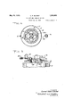
- Fig. 1 is a plan view of a car lift and greasing device built in accordance with my invention and installed ready for use
- Fig. 2 is a side elevation partly diagrammatic of the structure shown in Fig. 1
- F ig. 3 is a section on an enlarged scale as seen on line 3-3 of F ig. 2
- Fig. 4 is a section as seen on line 4 4 of Fig. 3
- Fig. 5 is a section on an enlarged scale as seen on line 5)5 of Fig. 1.
- a structural iron frame work 10 comprising a pair of parallel beams 11 and 12 attached to a center plate 13, is secured to a. hollow plunger 14, slidable within a cylinder 15, suitable guiding and sealing means generally denoted by 16 being provided at the upper end of the latter.
- Cylinder 15 is secured within a second cylinder 17 preferably placed in the ground with its top flush with a concrete slab 18,l laid on top of the ground. Cylinder 17 forms an oil reservoir,
- a discharge pipe -24 connected 4to the bottom ofV cylinder 15 through a needle valve 25, arranged to be conveniently manipulated :by a rod Y26 leading to the surface ofslab 18.
- valve 23 is then manipulated to admit air pressure tothe surface of 'the oil reservo-ir 17.- The'oi'l is forced out of the reservoir through pipe 24 and valve 25 into cylinder 15 beneath the head 14a' of the plunger, serving to raise the plu-nger and frame with the car thereon. lVhen the car rvreaches the desired height, valve 23 isClCsed, llocking the air pressure in' thereservoir and holding the plunger elevated.
- valven23 ' is lopened to the atmosphere, allowing the air from reservoir 17 to escape and permitting the oil to return from v'cylin-A der 1 lxthrough pipe 24 into the reservoir.
- Valve 25 serves to regulate the speed at which oil passes from the reservoir yto the cylinder 0r vice Versa and accordingly the-'speed at which the plunger is raised or lowered, and the valve opening is adjusted by rod .26.k
- the upper end 'of plungerA 14 is closed by a headV 14?) held in position by cap 'screws and having 'secured to -it al plurality of tubes 34, extending nearly to the bottom ofthe plunger.
- the head has an opening over each tube, closed by a plug provided with an elbow towhich is attached a hose 35. These are adapted-to lay lalong the side members 11 and 12 of theframe.
- Each of tubes 34 has a plunger ⁇ 36 formed with two cupleathers l37 secured on a travel limiting rod 38 and guide plate 39. VExtending through a packing gland 4in head 14a isan'air tube 40, reaching nearly to the top ofthe plunger when it is in its lowered position.
- Pipi-ng 41l serves tol connect this air tube with the air receiver 22, a control valve 42 being provided.
- a pipe 43 is secured in head 146, extending nearly to the bottom of the plunger, and has a hose 44 similar to hoses 35 connected to it, a metering device 45 being interposed.
- a plug 46 is mounted in head 14?), permitting access n to the inside oi' the plunger for replenishing the cylinder 15 with gear oil.
- Each hose is provided with a valve or other means to control the outflow of iluid through it, those on the hoses 35 being of a type to coact with greasing connections usually provided on automotive vehicles and preferably l including a booster as indicated by 47.
- greasing connections usually provided on automotive vehicles and preferably l including a booster as indicated by 47.
- Each of tubes 34 is filled with a desired lubricant, such as cup grease or universal joint grease, plungers V36 being at the bottom, the filling being done by removing the lplugs in head 14?).
- a desired lubricant such as cup grease or universal joint grease
- plungers V36 being at the bottom, the filling being done by removing the lplugs in head 14?.
- the space within the plunger surrounding tubes 34 is filled with gear. oil by remov ing Vplug 46 ⁇ . Air pressure is then admitted by opening valve 42.
- the pres@ sure will be applied 'to the gear oil and to the grease within tubes 34, plungers 36 serving to separate the liquids. Oil or grease may now be discharged as desired by manipulating the valves at the ends of the hoses, previously ⁇ described.
- an ejector 50 is provided. By closing valve 42 and .opening valves 51 and 52, a partial vacuum: may be created in plunger 14 (below plungers 36) which will cause the latter to travel downward.
- Vhat I claim is In a car lift and grease dispenser wherein there is a reservoir cylinder for motive liquid, a hydraulic jack cylinder disposed within ⁇ said reservoir cylinder, a hollow plunger reciprocatingly mounted within said hydraulic jack cylinder, said plunger being partially filled with lubricating liquid, means on said plunger to engage a car to lift the latter: the combination of said hydraulic jack cylinder and said plunger; a plurality of dispensing cylinders within said plunger and open at their lower ends to the space within said plunger, floating pistons in said dispensing cylinders influenced to move by pressure applied to the lubricating liquid in said plunger and to discharge lubricating liquids contained in said dispensing cylinders, means to supply a motive fluid under pressure to the lubricating liquid contained in the bore of said plunger and to withdraw said motive fluid, and selectively operable controllable means for controlling the discharge of liquid from said dispensing cylinders by action of said pistons thereon and from said hollow plunger.
Landscapes
- Engineering & Computer Science (AREA)
- Mechanical Engineering (AREA)
- Loading And Unloading Of Fuel Tanks Or Ships (AREA)
Description
GAR LIFT AND GREASING DEVICE y Filed Jan. 25, 1930 5 Sheets-Sheet 2 a5 /45 a5 l i E 1N VENTO/e A TTORNE YS May 16, 1933. C, R BUCHET 1,908,685
CAR LIFT AND GREASING DEVICE Filed Jan. 25.v 1930 3 Sheets-Sheet 3 [N VENTOR BY Con/"aaer @Maf A Troie/VE YS Patented May 16, 1933 FFiaCIE CONRAD nomina:V BUCKET, oF-Lois Attentes, CALFoRNIA, AssIGNo'RY DIRECT Aun MESNE ASSIGNMENTYTO ADJUSTO EQIPI'EENT COMPANY, OF LOS ANGELES, CALI- FORNIA, A CORPORATGN 0F CALIJORNIAA CAR LIFT AND Genesius y DEVICE- Application led January 25, 1930. Serial 116.7423297.
rlfhis invention relates to la device for elevating an automative vehiclea distance above ground to allow convenient access to its running gear, such as for purposes `of lubrication, inspection and repair. Such devices sometimes use mechanical means for lifting the car, but often employ hydraulic means, and it is to this latter type that this invention appertains. Diderent .lubricants are used at dierent points on a chassis and it has heretofore been the custom to provide a locker for storing these. It is a primary object of this invention to provide a car lift in which the lubricants used may be housed and in which the greasing appliances form an integral part of the structure. Other objects include the provision of such a device which is safe and convenient to use and which may be economically constructed and installed.
These objects together with other objects and corresponding accomplishments are obtained by means of the embodiment of my invention illustrated in the accompanying drawings in which Fig. 1 is a plan view of a car lift and greasing device built in accordance with my invention and installed ready for use; Fig. 2 is a side elevation partly diagrammatic of the structure shown in Fig. 1; F ig. 3 is a section on an enlarged scale as seen on line 3-3 of F ig. 2; Fig. 4 is a section as seen on line 4 4 of Fig. 3; and Fig. 5 is a section on an enlarged scale as seen on line 5)5 of Fig. 1.
Referring with more particularity to drawings, a structural iron frame work 10, comprising a pair of parallel beams 11 and 12 attached to a center plate 13, is secured to a. hollow plunger 14, slidable within a cylinder 15, suitable guiding and sealing means generally denoted by 16 being provided at the upper end of the latter. Cylinder 15 is secured within a second cylinder 17 preferably placed in the ground with its top flush with a concrete slab 18,l laid on top of the ground. Cylinder 17 forms an oil reservoir,
the space between it and cylinder 15 beingV filled with oil to the level of the air inlet pipe 19. This latter is provided with a T the y 2O and plug21 for -replenis'hing the 'oil supply for lifting; Pipe 19 is connectedto an air receiver 22. (see'Fig. which may be cennected to an air compressor (not shown) and is provided with a three-way valve 23.-
Atthe bottom lof the reservoir -is a discharge pipe -24 connected 4to the bottom ofV cylinder 15 through a needle valve 25, arranged to be conveniently manipulated :by a rod Y26 leading to the surface ofslab 18. v The operation and use of a device as just described is well known. The frame 10.is lowered to lthe ground and the car/driven astraddle over it until the front axle is posi@ tioned over blocks 30 and the rear axlev over plate 31. The valve 23 is then manipulated to admit air pressure tothe surface of 'the oil reservo-ir 17.- The'oi'l is forced out of the reservoir through pipe 24 and valve 25 into cylinder 15 beneath the head 14a' of the plunger, serving to raise the plu-nger and frame with the car thereon. lVhen the car rvreaches the desired height, valve 23 isClCsed, llocking the air pressure in' thereservoir and holding the plunger elevated. When it is desired. to lower the car, valven23 'is lopened to the atmosphere, allowing the air from reservoir 17 to escape and permitting the oil to return from v'cylin-A der 1 lxthrough pipe 24 into the reservoir. Valve 25 serves to regulate the speed at which oil passes from the reservoir yto the cylinder 0r vice Versa and accordingly the-'speed at which the plunger is raised or lowered, and the valve opening is adjusted by rod .26.k
The upper end 'of plungerA 14 is closed by a headV 14?) held in position by cap 'screws and having 'secured to -it al plurality of tubes 34, extending nearly to the bottom ofthe plunger. The head has an opening over each tube, closed by a plug provided with an elbow towhich is attached a hose 35. These are adapted-to lay lalong the side members 11 and 12 of theframe. Each of tubes 34 has a plunger `36 formed with two cupleathers l37 secured on a travel limiting rod 38 and guide plate 39. VExtending through a packing gland 4in head 14a isan'air tube 40, reaching nearly to the top ofthe plunger when it is in its lowered position. Pipi-ng 41l serves tol connect this air tube with the air receiver 22, a control valve 42 being provided. A pipe 43 is secured in head 146, extending nearly to the bottom of the plunger, and has a hose 44 similar to hoses 35 connected to it, a metering device 45 being interposed. A plug 46 is mounted in head 14?), permitting access n to the inside oi' the plunger for replenishing the cylinder 15 with gear oil. i
Each hose is provided with a valve or other means to control the outflow of iluid through it, those on the hoses 35 being of a type to coact with greasing connections usually provided on automotive vehicles and preferably l including a booster as indicated by 47. Such devices being well known in the art and forming no part of the present invention will not be further described.
The operation of the ear lift having been previously described, the operation of the greasing device will now be described. Each of tubes 34 is filled with a desired lubricant, suchas cup grease or universal joint grease, plungers V36 being at the bottom, the filling being done by removing the lplugs in head 14?). The space within the plunger surrounding tubes 34 is filled with gear. oil by remov ing Vplug 46`. Air pressure is then admitted by opening valve 42. Obviously, the pres@ sure will be applied 'to the gear oil and to the grease within tubes 34, plungers 36 serving to separate the liquids. Oil or grease may now be discharged as desired by manipulating the valves at the ends of the hoses, previously` described.
To conveniently return plungers 36 to their initial positions when it is desired to replenish the grease in tubes 34, an ejector 50 is provided. By closing valve 42 and . opening valves 51 and 52, a partial vacuum: may be created in plunger 14 (below plungers 36) which will cause the latter to travel downward.
`It will be noted that withdrawal of lui' bricant from any of the lubricant chambers will not aiect the elevation of the hoist or device. The fluid .transmission system for lifting is unaffected by withdrawal of lubricant and vice versa. However, the parts are grouped and interrelated to form a compact unit, in which the cylinder 17 constitutesa reservoir cylinder for motive Huid, cylinder 15 av hydraulic jack cylinder yand tubes4 34 grease dispensing cylinders.
Vhat I claim is In a car lift and grease dispenser wherein there is a reservoir cylinder for motive liquid, a hydraulic jack cylinder disposed within` said reservoir cylinder, a hollow plunger reciprocatingly mounted within said hydraulic jack cylinder, said plunger being partially filled with lubricating liquid, means on said plunger to engage a car to lift the latter: the combination of said hydraulic jack cylinder and said plunger; a plurality of dispensing cylinders within said plunger and open at their lower ends to the space within said plunger, floating pistons in said dispensing cylinders influenced to move by pressure applied to the lubricating liquid in said plunger and to discharge lubricating liquids contained in said dispensing cylinders, means to supply a motive fluid under pressure to the lubricating liquid contained in the bore of said plunger and to withdraw said motive fluid, and selectively operable controllable means for controlling the discharge of liquid from said dispensing cylinders by action of said pistons thereon and from said hollow plunger.
In witness thatvI claim the foregoing I have hereunto subscribed my name this 10th day of January, 1930.
CONRAD ROBERT BUCI-IET.
Priority Applications (1)
| Application Number | Priority Date | Filing Date | Title |
|---|---|---|---|
| US423297A US1908685A (en) | 1930-01-25 | 1930-01-25 | Car lift and greasing device |
Applications Claiming Priority (1)
| Application Number | Priority Date | Filing Date | Title |
|---|---|---|---|
| US423297A US1908685A (en) | 1930-01-25 | 1930-01-25 | Car lift and greasing device |
Publications (1)
| Publication Number | Publication Date |
|---|---|
| US1908685A true US1908685A (en) | 1933-05-16 |
Family
ID=23678362
Family Applications (1)
| Application Number | Title | Priority Date | Filing Date |
|---|---|---|---|
| US423297A Expired - Lifetime US1908685A (en) | 1930-01-25 | 1930-01-25 | Car lift and greasing device |
Country Status (1)
| Country | Link |
|---|---|
| US (1) | US1908685A (en) |
Cited By (2)
| Publication number | Priority date | Publication date | Assignee | Title |
|---|---|---|---|---|
| DE1178569B (en) * | 1961-11-16 | 1964-09-24 | Mobil Oil A G | Above-floor vehicle lifting platform with one-sided cantilever arm |
| DE102015114268B4 (en) * | 2015-08-27 | 2019-06-13 | Autop Maschinenbau Gmbh | Platform for work on motor vehicles |
-
1930
- 1930-01-25 US US423297A patent/US1908685A/en not_active Expired - Lifetime
Cited By (2)
| Publication number | Priority date | Publication date | Assignee | Title |
|---|---|---|---|---|
| DE1178569B (en) * | 1961-11-16 | 1964-09-24 | Mobil Oil A G | Above-floor vehicle lifting platform with one-sided cantilever arm |
| DE102015114268B4 (en) * | 2015-08-27 | 2019-06-13 | Autop Maschinenbau Gmbh | Platform for work on motor vehicles |
Similar Documents
| Publication | Publication Date | Title |
|---|---|---|
| US1903887A (en) | Hydraulic jack | |
| US1525447A (en) | Apparatus for elevating automobiles | |
| US1944351A (en) | Hoist mechanism | |
| US2251293A (en) | Hydraulic car lift | |
| US1908685A (en) | Car lift and greasing device | |
| US1920285A (en) | Fluid motor | |
| US2204365A (en) | Lifting platform | |
| US1957151A (en) | Air jack | |
| US1760989A (en) | Piston puller and cylinder-bushing press | |
| US1979788A (en) | Chocking device for vehicle lifts | |
| US1609015A (en) | Grease-charging apparatus | |
| US2288511A (en) | Automobile lift | |
| US2217461A (en) | Hydraulic brake apparatus | |
| US2056954A (en) | Jacking apparatus | |
| US1815907A (en) | Elevator | |
| US2550674A (en) | Supporting column | |
| US1557385A (en) | Vehicle jack | |
| US2394437A (en) | Lubrication system | |
| US2181073A (en) | Hydraulic brake system flusher and bleeder | |
| US1689145A (en) | Turntable lift | |
| US1987083A (en) | Hoist | |
| US1958960A (en) | Hydraulic lift | |
| US1624160A (en) | Hydraulic press | |
| US2663150A (en) | Hydraulic system and multipurpose control valve | |
| US2042727A (en) | Hydraulic jack |