US190844A - Improvement in quilting-frames and clothes-bars - Google Patents
Improvement in quilting-frames and clothes-bars Download PDFInfo
- Publication number
- US190844A US190844A US190844DA US190844A US 190844 A US190844 A US 190844A US 190844D A US190844D A US 190844DA US 190844 A US190844 A US 190844A
- Authority
- US
- United States
- Prior art keywords
- quilting
- clothes
- bars
- frames
- improvement
- Prior art date
- Legal status (The legal status is an assumption and is not a legal conclusion. Google has not performed a legal analysis and makes no representation as to the accuracy of the status listed.)
- Expired - Lifetime
Links
- 238000010276 construction Methods 0.000 description 4
- 238000001035 drying Methods 0.000 description 4
Images
Classifications
-
- D—TEXTILES; PAPER
- D05—SEWING; EMBROIDERING; TUFTING
- D05C—EMBROIDERING; TUFTING
- D05C1/00—Apparatus, devices, or tools for hand embroidering
- D05C1/02—Work frames
Definitions
- Figure l of the drawings is a representation of a central vertical section of my invention used as a quilting-frame.
- Fig. 2 is a plan view of the same; and
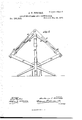
- Fig. 3 is a side elevation of the same, when used as a clothes-bar.
- This invention relates to quilting -frames which are adapted to be converted into racks for holding clothes while drying; and it consists in the construction, combination, and arrangement hereinafter set forth.
- each standard A designates the two main standards of my quilting-frame, and A a brace-bar connecting the same.
- To the upper end of each standard A are pivoted two arms, B B, which extend in opposite directions.
- the two pairs of said arms constitute the two sides of the top of my quiltingframe, and each one of said arms is provided at its outer end with a pivoted prop, G.
- Each of said arms or bars B is longitudinally slotted at B from side to side, and provided with a vertical series of perforations, b.
- the journals of transversely-arranged quiltingmollers D rest in said slots, and said rollers may be adjusted therein toward or from one another, to suit the character of the work for which they may be employed.
- rollers By shifting lockingpins d from one to another of said perforations b the said rollers are locked in their new position, and prevented from approaching one another too closely. Said rollers derive their motion, through bands or belts E, from a shaft, F, which is journaled in standards A, and operated by a crank, G.
Description
.A. E. 2 Sh eetS-She6t 2.
v QUILTING-FRAME AND CLOTHES-BAR. I No. 190,844. Patented May15,1877.
INVENTOR- NE ES Mow w fma ATTORNEY;
N-PEFERS, PHOTD-LITHOGEAPHER. WASHINGTON. D C,
UNITED STATES PATENT OFFICE.
ANTHONY E. FURNESS, OF OGDENSBURG, NEW YORK.
IMPROVEMENT IN QUILTING-FRAMES AND CLOTHES-BARS.
Specification forming part of Letters Patent No. 190,844, dated May 15. 1877; application filed March 10, 1877.
To all whom it may concern Be it known that I, ANTHONY E. FU'RNESS, of Ogdensburg, in the county of St. Lawrence and State of New York, have invented a new and valuable Improvement in Quilting-Frames and Clothes-Bars; and I do hereby declare that the following is a full, clear, and exact description of the construction and operation of the same, reference being had to the annexed drawings, making a part of this specification. and to the letters and figures of reference marked thereon.
Figure l of the drawings is a representation of a central vertical section of my invention used as a quilting-frame. Fig. 2 is a plan view of the same; and Fig. 3 is a side elevation of the same, when used as a clothes-bar.
This invention relates to quilting -frames which are adapted to be converted into racks for holding clothes while drying; and it consists in the construction, combination, and arrangement hereinafter set forth.
In the accompanying drawings, Adesignates the two main standards of my quilting-frame, and A a brace-bar connecting the same. To the upper end of each standard A are pivoted two arms, B B, which extend in opposite directions. The two pairs of said arms constitute the two sides of the top of my quiltingframe, and each one of said arms is provided at its outer end with a pivoted prop, G. Each of said arms or bars B is longitudinally slotted at B from side to side, and provided with a vertical series of perforations, b. The journals of transversely-arranged quiltingmollers D rest in said slots, and said rollers may be adjusted therein toward or from one another, to suit the character of the work for which they may be employed. By shifting lockingpins d from one to another of said perforations b the said rollers are locked in their new position, and prevented from approaching one another too closely. Said rollers derive their motion, through bands or belts E, from a shaft, F, which is journaled in standards A, and operated by a crank, G.
To transform said quilting-frame into a clothes-rack, arms or bars B B are bent obliquely downward on their pivots, and props G O are bent inward across one another, as shown in Fig. 3. To facilitate this latter move ment the lower part of each standard A is formed into, or placed upon, an open tripod, H. The said props O G then have their lower ends upon the ground, and they and said tripods H H mutually brace one another.
I am aware that heretofore quilting-frames have been converted into racks for holding clothes while drying, as shown in the patent granted to G. A. Mallory and J. J. Fish, November 12, 1867, No. 70,871, and I therefore lay no claim, broadly, to such invention in this application.
What I claim as new, and desire to secure by Letters Patent, is-
l. The combination of standards A A, having tripod-supports H H, with arms B B and props O G, adapted to be folded transversely to form a clothes-rack, substantially as and for the purpose set forth.
2. The combination of standards A A with slotted and perforated arms B B, props (J (J, rollers D D, crank-shaft F, and belt-gearing, substantially as and for the purpose set forth.
In testimony that I claim the above I have hereunto subscribed my name in the presence of two witnesses.
ANTHONY E. FURNESS.
Witnesses:
NATHANIEL WELLS, MICHAEL LEONARD, Jr.
Publications (1)
| Publication Number | Publication Date |
|---|---|
| US190844A true US190844A (en) | 1877-05-15 |
Family
ID=2260251
Family Applications (1)
| Application Number | Title | Priority Date | Filing Date |
|---|---|---|---|
| US190844D Expired - Lifetime US190844A (en) | Improvement in quilting-frames and clothes-bars |
Country Status (1)
| Country | Link |
|---|---|
| US (1) | US190844A (en) |
-
0
- US US190844D patent/US190844A/en not_active Expired - Lifetime
Similar Documents
| Publication | Publication Date | Title |
|---|---|---|
| US190844A (en) | Improvement in quilting-frames and clothes-bars | |
| US196679A (en) | Improvement in combined ladder and steps | |
| US612256A (en) | Painters roof-bracket | |
| US146308A (en) | Improvement in clothes-driers | |
| US366096A (en) | Nathaniel j | |
| US264000A (en) | Clothes-drier | |
| US365196A (en) | Clothes-line support | |
| US526907A (en) | Easel | |
| US141044A (en) | Improvement in washing-machines | |
| US1424626A (en) | Clothesline | |
| US150876A (en) | Improvement in ironing-tables | |
| US296209A (en) | Wash-bench and step-ladder | |
| US1024720A (en) | Ironing-board. | |
| US183189A (en) | Improvement in clothes-driers | |
| US267857A (en) | Ironing-stand | |
| US372356A (en) | Folding ironing board and stand | |
| US170848A (en) | Improvement in ironing-tables | |
| US145738A (en) | Improvement in combined step-ladders and ironing-boards | |
| US145799A (en) | Improvement in washing-machines | |
| US1834488A (en) | Folding ironing table | |
| US140625A (en) | Improvement in washing-machines | |
| US164288A (en) | Improvement in ironing-tables | |
| US194750A (en) | Improvement in washing-machines | |
| US183679A (en) | Improvement in clothes-driers | |
| US143469A (en) | Improvement in supports for wash-tubs |