US1908182A - Machine for bending sheet metal shapes - Google Patents
Machine for bending sheet metal shapes Download PDFInfo
- Publication number
- US1908182A US1908182A US478637A US47863730A US1908182A US 1908182 A US1908182 A US 1908182A US 478637 A US478637 A US 478637A US 47863730 A US47863730 A US 47863730A US 1908182 A US1908182 A US 1908182A
- Authority
- US
- United States
- Prior art keywords
- machine
- sheet metal
- yoke
- shafts
- bending sheet
- Prior art date
- Legal status (The legal status is an assumption and is not a legal conclusion. Google has not performed a legal analysis and makes no representation as to the accuracy of the status listed.)
- Expired - Lifetime
Links
- 239000002184 metal Substances 0.000 title description 12
- 238000005452 bending Methods 0.000 title description 4
- 238000005096 rolling process Methods 0.000 description 4
- 238000000034 method Methods 0.000 description 2
- 230000004308 accommodation Effects 0.000 description 1
- 230000006835 compression Effects 0.000 description 1
- 238000007906 compression Methods 0.000 description 1
- 238000010276 construction Methods 0.000 description 1
- 238000004519 manufacturing process Methods 0.000 description 1
- 238000012986 modification Methods 0.000 description 1
- 230000004048 modification Effects 0.000 description 1
Images

Classifications
-
- B—PERFORMING OPERATIONS; TRANSPORTING
- B21—MECHANICAL METAL-WORKING WITHOUT ESSENTIALLY REMOVING MATERIAL; PUNCHING METAL
- B21D—WORKING OR PROCESSING OF SHEET METAL OR METAL TUBES, RODS OR PROFILES WITHOUT ESSENTIALLY REMOVING MATERIAL; PUNCHING METAL
- B21D5/00—Bending sheet metal along straight lines, e.g. to form simple curves
- B21D5/06—Bending sheet metal along straight lines, e.g. to form simple curves by drawing procedure making use of dies or forming-rollers, e.g. making profiles
- B21D5/08—Bending sheet metal along straight lines, e.g. to form simple curves by drawing procedure making use of dies or forming-rollers, e.g. making profiles making use of forming-rollers
Definitions
- an object of this invention to provide means for stably supporting the free ends of the die roll carrying shafts without producing obstructions preventing the accommodation of relatively wide sheets of metal.
- Another object of this inventon is to provide a powerful, eiilcient drive in which power is distributed to each individual pair of rolls, thus requiring less power to operate than would be necessary in other types of forming and rolling machines; and further:
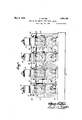
- Figure 1 representsa front elevational View of a machine embodying the invention. 1
- Figure 2 represents an end view of the machine.
- Figure 3 represents a perspective view of a section of the machine.
- Figure 1 represents a sectional view taken on the line 4.4 of Figure 2.
- the rolling machine is shown to include a base 6 upon which are mounted a plurality of rear heads 7 and a plurality of front heads 8 in which are j ournalled lower shafts 9 having fixed thereto the gears 10.
- a base 6 upon which are mounted a plurality of rear heads 7 and a plurality of front heads 8 in which are j ournalled lower shafts 9 having fixed thereto the gears 10.
- the description will be confined to one section such as is shown in Figure 2. 7 7
- the housings 13 and 16 respectively are provided with raised fiat portions 18 and 17 respectively, which support a yoke'19, the latter being rigidly secured to the flat portions'18 and 17 by means of bolts 20.
- the yoke 19 has an enlarged portion 21 provided with an aperture through which passes a bolt 22 having an integral collar 23 which engages the upper side of yoke 19, and a hexagonal head 24 by means of whichthe bolt may be rotated.
- the lower end of the bolt has a threaded portion 25 in threaded engagement with a bar 26, upon which rests a compression spring 27 the latter encircling the bolt and being housed in a recess 28 in the yoke 19.
- the bar 26 is secured by bolts 30 to transverse end bars 29' and intermediate plates 29, the bar'29 and plates 29 being secured to the uprights 14 and 15 by bolts 31. Also secured to bar'29 and plates 29 by means of bolts 32,
- a bearing 38 Secured to the forward end of yoke 19 by means of bolts 39, is a bearing 38 which supports the free end of shaft 12.
- the free end of shaft 9 is supported in a'bearing 10 which is fixed to the base 6 by means of bolts 41.
- the bearings 38 and 40 are sufliciently spaced so that no obstruction would be in the path of the wide metal sheet which may be in the process of being formed by the roll dies as and 4t3fixed respectively to shafts 12 and 9.
- a metal'sheet to be shaped is introduced into the machine at the end thereof and passes between the bearings 38 and 40 as shown in Figure 2. It will be seen that the yoke 19 is rigidly connected to the housings '13 and 16 and consequently any adjustment of the yoke will be transmitted to the housing.
- a base In a rolling machine, a base, a plurality of sections mounted on the base, each section including a front head and a rear head,-lower
Landscapes
- Engineering & Computer Science (AREA)
- Mechanical Engineering (AREA)
- Bending Of Plates, Rods, And Pipes (AREA)
Description
May 9, 1933. A. RAFTER MACHiNE FOR BENDING SHEET METAL SHAPES 2 Sheets-Sheet l NV T'OR Filed Aug. 29, 1950 ATTORNEY May'9, 1933. A. RAFTER MACHINE FOR BENDING SHEET METAL SHAPES Filed Aug. 29, 1930 2 Sheets-Sheet 2 Patented May 9, 1933 UNITED STATES PATENTOFFICE ALBERT RAFTER, or BELLEvILL-E, NEW JERSEY,'ASSIG1\TOR mo RAFTER MACHINE COMPANY, or BELLEVILLE, NEW JERSEYQA PARTNERsHIr-or NEWLJERSEIY com POSED or ALBERT RAET'ER AND JOHN G. RAFTLEB, JR.
MACHINE r03 BENDING SHEET METAL sHnrEs Application filed August 29, 1930. Serial No. 478,637.
are mounted on shafts supported in a manner which necessitates the passing of the metal sheets between the supports. Qbviously, such arrangement limits the width of the metal sheet which may be operated upon.
Inasmuch it is necessary at times to shape the edges of relatively wide sheets, that is, of a width greater than the width of the die rolls, there has been provided an open face machine in which the shafts are supported only at their driven ends, thus leaving the free ends of the shafts unsupported and eliminating obstructions to wide sheets of metal.
However. such machines have been found unsatisfactory in that the unsupported ends of the shafts are deflected when pressure is applied thereto, with the result that the metal sheet is formed with round corners instead of the desired sharp corners. Although the shafts used on such machines are comparatively short, and have appreciable diameters, they have been found to deflect as much as one-siXty-fourth of an inch duringthe forming operation.
It is therefore, an object of this invention to provide means for stably supporting the free ends of the die roll carrying shafts without producing obstructions preventing the accommodation of relatively wide sheets of metal.
Another object of this inventon is to provide a powerful, eiilcient drive in which power is distributed to each individual pair of rolls, thus requiring less power to operate than would be necessary in other types of forming and rolling machines; and further:
To provide a machine of this character that eliminates springing of the shafts and die rolls, and provides means to keep said members in perfect alinement, and is so constructed that the rolls can be easily removed and replaced in afrelatively short space oftime, a desideratum of importancein modern sys toms of production.
This and other advantageous objects which will later appear, are accomplished by the simple and practical construction and arrangement of'parts hereinafter described and exhibited in the accompanying drawings, forming part hereof, and in which:
Figure 1 representsa front elevational View of a machine embodying the invention. 1
Figure 2 represents an end view of the machine. p
Figure 3 represents a perspective view of a section of the machine.
Figure 1 represents a sectional view taken on the line 4.4 of Figure 2.
Referring to the drawings, the rolling machine is shown to include a base 6 upon which are mounted a plurality of rear heads 7 and a plurality of front heads 8 in which are j ournalled lower shafts 9 having fixed thereto the gears 10. Inasmuch as the structure of the several sections is identical, the description will be confined to one section such as is shown in Figure 2. 7 7
Integral with heads 7 and 8, are respectively sides uprights 14 and15 between which are slidably mounted the housings 13 and 16 having journalled therein the upper shaft 12 to which is fixed a gear 11 inmesh with the gear 10.
V The structure above described is identical with that disclosed in my application Serial No. 288,585, filed June 27, 1928, in which it is shown that the shafts 9 and 12 are driven by means of bevelled gear 5 in mesh with a bevelled gear on the driving shaft 4.
The housings 13 and 16 respectively are provided with raised fiat portions 18 and 17 respectively, which support a yoke'19, the latter being rigidly secured to the flat portions'18 and 17 by means of bolts 20.
The yoke 19 has an enlarged portion 21 provided with an aperture through which passes a bolt 22 having an integral collar 23 which engages the upper side of yoke 19, and a hexagonal head 24 by means of whichthe bolt may be rotated.
The lower end of the bolt has a threaded portion 25 in threaded engagement with a bar 26, upon which rests a compression spring 27 the latter encircling the bolt and being housed in a recess 28 in the yoke 19.
The bar 26 is secured by bolts 30 to transverse end bars 29' and intermediate plates 29, the bar'29 and plates 29 being secured to the uprights 14 and 15 by bolts 31. Also secured to bar'29 and plates 29 by means of bolts 32,
is a rear bar 33 in threaded engagement with a bolt 35 passing through an aperture in the enlarged portion 34 at the rear of yoke 19. Downward movement of the bolt 35 is limited by a collar 36 fixed thereto by a pin; and upward movement of bolt 35 is limited by an integral collar 37 positioned in a recess on the under side of yoke 19.
Secured to the forward end of yoke 19 by means of bolts 39, is a bearing 38 which supports the free end of shaft 12. The free end of shaft 9 is supported in a'bearing 10 which is fixed to the base 6 by means of bolts 41. As clearly shown in Figure 2, the bearings 38 and 40 are sufliciently spaced so that no obstruction would be in the path of the wide metal sheet which may be in the process of being formed by the roll dies as and 4t3fixed respectively to shafts 12 and 9. In operation, a metal'sheet to be shaped is introduced into the machine at the end thereof and passes between the bearings 38 and 40 as shown in Figure 2. It will be seen that the yoke 19 is rigidly connected to the housings '13 and 16 and consequently any adjustment of the yoke will be transmitted to the housing.
bearings mounted on the heads, a lower shaft journalled in the lower bearings, upper housings slidably mounted in the heads, a yoke fixed to said upper housings, an upper shaft journalled in the housings, plates rigidly attached to the heads, said plates acting as guides for the yokes and preventing lateral movement of the yokes and spacing the sections, a bar extending the length of the machine, said bar being supported by the plates,-
and'means associated with the bar and yokes to ad ust the yokes vertically.
This specification signed this 9th day of 7 June, 1931.
ALBERT RAFTER.
When adjustment of the housing is desired,
the bolt 22 is rotated to cause the yoke to be moved-towards or away from the bar 26. l/Vhen the bolt is loosened, or withdrawn from the bar 26, the coil spring 27 assists in raising the yoke 19. Simultaneously with the ad ju'stment of bolt 22 it is necessary also to ad just bolt 35. V 7
From the'above description, it will be seen that I have provided a simple expedient for rigidly supporting shafts on a rolling 1nachine without in any Way obstructing the movement of relatively wide sheets of metal which may be in the process of being shaped by the machine. v The foregoing disclosure is to be regarded as descriptive and illustrative only, and not as restrictive or limitative of the invention, of which obviously an embodiment may be constructed including many modifications .without departing from the'general scope herein indicated and denoted in the appended claim. 7 7
Having thus described my invention, what I claim as new and desire to secure by Letters Patent, is:
In a rolling machine, a base, a plurality of sections mounted on the base, each section including a front head and a rear head,-lower
Priority Applications (1)
| Application Number | Priority Date | Filing Date | Title |
|---|---|---|---|
| US478637A US1908182A (en) | 1930-08-29 | 1930-08-29 | Machine for bending sheet metal shapes |
Applications Claiming Priority (1)
| Application Number | Priority Date | Filing Date | Title |
|---|---|---|---|
| US478637A US1908182A (en) | 1930-08-29 | 1930-08-29 | Machine for bending sheet metal shapes |
Publications (1)
| Publication Number | Publication Date |
|---|---|
| US1908182A true US1908182A (en) | 1933-05-09 |
Family
ID=23900752
Family Applications (1)
| Application Number | Title | Priority Date | Filing Date |
|---|---|---|---|
| US478637A Expired - Lifetime US1908182A (en) | 1930-08-29 | 1930-08-29 | Machine for bending sheet metal shapes |
Country Status (1)
| Country | Link |
|---|---|
| US (1) | US1908182A (en) |
-
1930
- 1930-08-29 US US478637A patent/US1908182A/en not_active Expired - Lifetime
Similar Documents
| Publication | Publication Date | Title |
|---|---|---|
| DE102011006357A1 (en) | Rolling mill for producing a metal strip and method for producing a rolling mill | |
| US2163504A (en) | Processing machine | |
| US1908182A (en) | Machine for bending sheet metal shapes | |
| US3621693A (en) | Straightening machine for structural workpieces | |
| US1266545A (en) | Apparatus for shaping metal channel-bars. | |
| US1373571A (en) | Drawing-press | |
| US1792122A (en) | Machine for rolling sheet-metal shapes | |
| US2145526A (en) | Method of producing profiled sections from sheet metal by rolling | |
| US1376497A (en) | Rolling or bending machine | |
| US1383673A (en) | Punching-machine | |
| US1356748A (en) | Drawing-press | |
| US760448A (en) | Machine for rolling helicoids or spiral conveyers. | |
| US188741A (en) | Improvement in metal-rolling | |
| AT93452B (en) | Tire rolling mill. | |
| US2147589A (en) | Apparatus for straightening bars, rounds, or the like | |
| DE961701C (en) | Rolling mill for reducing pipes | |
| US2049992A (en) | Pipe straightening machine | |
| US884314A (en) | Machine for coiling sheet metal. | |
| US827419A (en) | Apparatus for making corrugated metal sheets or plates. | |
| DE493019C (en) | Roll bending machine for the production of tubular workpieces | |
| US1051084A (en) | Machine for overhauling metal. | |
| US891126A (en) | Rolling-mill table. | |
| US1488909A (en) | Rolling mill | |
| US344383A (en) | kennedy | |
| US851435A (en) | Tube-rolling mill. |