US190332A - Improvement in drill-bits - Google Patents
Improvement in drill-bits Download PDFInfo
- Publication number
- US190332A US190332A US190332DA US190332A US 190332 A US190332 A US 190332A US 190332D A US190332D A US 190332DA US 190332 A US190332 A US 190332A
- Authority
- US
- United States
- Prior art keywords
- drill
- bits
- blade
- improvement
- bit
- Prior art date
- Legal status (The legal status is an assumption and is not a legal conclusion. Google has not performed a legal analysis and makes no representation as to the accuracy of the status listed.)
- Expired - Lifetime
Links
- 239000003245 coal Substances 0.000 description 4
- 240000004658 Medicago sativa Species 0.000 description 1
- 238000010276 construction Methods 0.000 description 1
- 238000005553 drilling Methods 0.000 description 1
- 238000004519 manufacturing process Methods 0.000 description 1
- 230000035515 penetration Effects 0.000 description 1
Images
Classifications
-
- E—FIXED CONSTRUCTIONS
- E21—EARTH OR ROCK DRILLING; MINING
- E21B—EARTH OR ROCK DRILLING; OBTAINING OIL, GAS, WATER, SOLUBLE OR MELTABLE MATERIALS OR A SLURRY OF MINERALS FROM WELLS
- E21B10/00—Drill bits
- E21B10/36—Percussion drill bits
- E21B10/40—Percussion drill bits with leading portion
Definitions
- the object of my invention is a drill-bit constructed as fully described hereafter, to secure a ready penetration of the coal, and ream the hole, and so as to be comparatively light in weight, strong, durable, and easily sharpened and repaired.
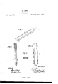
- Figure 1 is a perspective view of my improved bit.
- Fig. 2 is a face View;
- Fig. 3 a longitudinal section, and
- Fig. 4 a transverse section on the line 1 2.
- A is the shank or stock of the drill, which may be a continuation of the shaft or handle, or may be constructed for attachment to the shaft.
- the bit consists of a flat blade, at, of uniform, or nearly uniform, width, and having at both edges and on both sides flanges b.
- the end 0 of the blade extends beyond the terminations of the flanges b, and the lower edge is curved inward, and the lower and side edges are sharpened, as shown in the drawing.
- Each flanged edge I) is bent outward at the lower end to form a curved lip, e, which is rounded and sharpened at the edge 3 as shown.
- the projecting portion 0 of the blade penetrates and cuts the coal with its end and side edges, while the edges 3 of the lips e ream the opening.
- the cutter thus constructed may be cheaply manufactured, easily repaired and sharpened, will penetrate the coal much easier and with greater rapidity than ordinary cutters, and that, while the blade may be thin and comparatively light, the ribs impart great strength.
- the tool may be adapted to different grades of work, and that the relative action of the blade and reamers may he graduated with that nicety requisite to the most effective operation of the tool.
- a drill-bit consisting of a blade, at, and parallel ribs b at both edges and on both sides of said blade, the lower ends of the ribs being formed into sharp-edged lips e, and the end of the blade being sharpened, and projecting beyond said lips, as set forth.
Landscapes
- Engineering & Computer Science (AREA)
- Life Sciences & Earth Sciences (AREA)
- Geology (AREA)
- Mining & Mineral Resources (AREA)
- Mechanical Engineering (AREA)
- Physics & Mathematics (AREA)
- Environmental & Geological Engineering (AREA)
- Fluid Mechanics (AREA)
- General Life Sciences & Earth Sciences (AREA)
- Geochemistry & Mineralogy (AREA)
- Drilling Tools (AREA)
Description
M. JOHN.
DRILL-BIT. NO. 190,332. Patented. Mayl, 1877 7&4. Wilma a al c I iii 5J1 I ,Zwenl Grrro.
MATTHEW JOHN, PITTSTON, PENNSYLVANIA.
IMPROVEMENT IN DRILL-BITS.
Specification forming part of Letters Patent No. 190,332, dated May 1, 1877; application filed March 12, 1877. I
To all whom it may concern:
Be it known that I, MATTHEW JOHN, of
' Pittston, Luzerne county, Pennsylvania, have invented certain Improvements in Drill-Bits, of which the following is a specification The object of my invention is a drill-bit constructed as fully described hereafter, to secure a ready penetration of the coal, and ream the hole, and so as to be comparatively light in weight, strong, durable, and easily sharpened and repaired.
In the drawing, Figure 1 is a perspective view of my improved bit. Fig. 2 is a face View; Fig. 3, a longitudinal section, and Fig. 4 a transverse section on the line 1 2.
A is the shank or stock of the drill, which may be a continuation of the shaft or handle, or may be constructed for attachment to the shaft.
The bit consists of a flat blade, at, of uniform, or nearly uniform, width, and having at both edges and on both sides flanges b.
The end 0 of the blade extends beyond the terminations of the flanges b, and the lower edge is curved inward, and the lower and side edges are sharpened, as shown in the drawing.
Each flanged edge I) is bent outward at the lower end to form a curved lip, e, which is rounded and sharpened at the edge 3 as shown.
In drilling, the projecting portion 0 of the blade penetrates and cuts the coal with its end and side edges, while the edges 3 of the lips e ream the opening.
It has been found that the cutter thus constructed may be cheaply manufactured, easily repaired and sharpened, will penetrate the coal much easier and with greater rapidity than ordinary cutters, and that, while the blade may be thin and comparatively light, the ribs impart great strength.
It has also been found that, by graduating the point of the bit according to the quality or hardness of the coal to be drilled, the tool may be adapted to different grades of work, and that the relative action of the blade and reamers may he graduated with that nicety requisite to the most effective operation of the tool.
Without confining myself to the precise construction and proportions shown,
I claim- As a new article of manufacture, a drill-bit consisting of a blade, at, and parallel ribs b at both edges and on both sides of said blade, the lower ends of the ribs being formed into sharp-edged lips e, and the end of the blade being sharpened, and projecting beyond said lips, as set forth.
In testimony whereofI have signed my name to this specification in the presence of two subscribing witnesses.
MATTHEW JOHN.
Witnesses:
WALTER S. WILLIAMS, 1). S. Koou.
Publications (1)
| Publication Number | Publication Date |
|---|---|
| US190332A true US190332A (en) | 1877-05-01 |
Family
ID=2259739
Family Applications (1)
| Application Number | Title | Priority Date | Filing Date |
|---|---|---|---|
| US190332D Expired - Lifetime US190332A (en) | Improvement in drill-bits |
Country Status (1)
| Country | Link |
|---|---|
| US (1) | US190332A (en) |
-
0
- US US190332D patent/US190332A/en not_active Expired - Lifetime
Similar Documents
| Publication | Publication Date | Title |
|---|---|---|
| US1151861A (en) | Countersinking screw-head. | |
| US2773672A (en) | Drilling bit | |
| US190332A (en) | Improvement in drill-bits | |
| US358234A (en) | Painter s hacking-knife | |
| US342516A (en) | Earth-auger | |
| US1523518A (en) | Saw | |
| US305625A (en) | Thomas newey | |
| US361522A (en) | Auger-bit | |
| US968471A (en) | Earth-auger. | |
| US228421A (en) | Lycurgus thustoe | |
| US330580A (en) | Post-hole auger | |
| US751403A (en) | Chisel | |
| US181036A (en) | Improvement in post-hole borers | |
| US567977A (en) | Center-bit | |
| US502120A (en) | Mortising-tool | |
| US117237A (en) | Improvement in countersinks | |
| US305206A (en) | Chaeles j | |
| US570810A (en) | Earth-auger | |
| US513541A (en) | Cutting-bit for drilling-machines | |
| US235234A (en) | Auger | |
| US254733A (en) | Mortising-chisel | |
| US1106097A (en) | Earth-auger. | |
| US175745A (en) | Improvement in post-hole and well diggers | |
| US940426A (en) | Auger-bit. | |
| US192323A (en) | Improvement in mortise-chisels |