US1859984A - Folding fire escape ladder - Google Patents
Folding fire escape ladder Download PDFInfo
- Publication number
- US1859984A US1859984A US485989A US48598930A US1859984A US 1859984 A US1859984 A US 1859984A US 485989 A US485989 A US 485989A US 48598930 A US48598930 A US 48598930A US 1859984 A US1859984 A US 1859984A
- Authority
- US
- United States
- Prior art keywords
- rungs
- bars
- ladder
- fire escape
- bracket
- Prior art date
- Legal status (The legal status is an assumption and is not a legal conclusion. Google has not performed a legal analysis and makes no representation as to the accuracy of the status listed.)
- Expired - Lifetime
Links
- 238000010276 construction Methods 0.000 description 2
- 230000005484 gravity Effects 0.000 description 1
- 230000000670 limiting effect Effects 0.000 description 1
Images
Classifications
-
- E—FIXED CONSTRUCTIONS
- E06—DOORS, WINDOWS, SHUTTERS, OR ROLLER BLINDS IN GENERAL; LADDERS
- E06C—LADDERS
- E06C1/00—Ladders in general
- E06C1/02—Ladders in general with rigid longitudinal member or members
- E06C1/34—Ladders attached to structures, such as windows, cornices, poles, or the like
- E06C1/36—Ladders suspendable by hooks or the like
-
- E—FIXED CONSTRUCTIONS
- E06—DOORS, WINDOWS, SHUTTERS, OR ROLLER BLINDS IN GENERAL; LADDERS
- E06C—LADDERS
- E06C1/00—Ladders in general
- E06C1/52—Ladders in general with non-rigid longitudinal members
- E06C1/56—Rope or chain ladders
Definitions
- Figure 3 is a cross sectional view taken on the line 38 of Figure '1
- Figure 4 is a'front elevation showing the ladder extended, 1
- FIG. 5 is a side elevation showing the ladder extended, M
- Figure 6 is an enlarged sectional view taken on the line 6-6 of Figure 4, and
- a rigid frame is provided as at 10' which consists of a U-shaped bracket 11 at the top, and depending bars 12, rigidly riveted or otherwise connected therewith as at 13.
- a suspending hook device is provided at 14 adapted to engage over a window sill or the like which may comprise two side or hookmembers 15 connected by cross bars 16 and pivoted by a rod 17 to clips 18, fastened to the bracket 11.
- a multiplicity of rungs are employed as at 19, which are of U-shape as best shown in , Figure 3, and at their terminals have balls 22 are pivoted at 24 to the leaves '18. "As a retended.
- the I i 7 bars 12 are hollow or ofgchannel form and have constricted entrance slots at"21,whereby the balls, which are of, greater diameter than the width of the slots 21, cannot be later-- ally withdrawn therefrom.
- I H Lazy tong links or'levers 22 arepivoted together at 28 and at their-outer ends are pivoted at 24,'to the rungs.
- the uppermost links :(il: sult, the rungs may extend, by gravity, from I the position shown in Figure l'to that shown in Figures 4 and 5 with the links 22 limit ing the relative movement of the rungs.
- a ladderof the class described comprising' a bracket, bars extending therefrom of channeled form having restricted openings, rungs having enlarged terminals engageable in the channels of the bars and prevented from lateral disengagement therefrom, and
- link means pivoted together and to the rungs channeled form having restricted openings, I rungs having terminals with enlargements 'thereon engageable in the channels of the bars and prevented from lateral disengagement therefrom, link means connecting the rungs and' adapted to limit their opening movement, said enlargements constituting friction reducingmeans on the terminals of said rungs and within said channels, and 10 latch means securing the rungs in the bars 7 against extending movement.
- a ladder of the class described comprising a bracket, bars extending therefrom of channeled formhaving restricted openings, 15 rungs having terminals with enlargements thereon engageable in the channels of the,
- link means connecting the V rungs and adapted to limit their opening rmovements, said enlargements constituting' friction reducing means on the terminals of said rungs andwithin said channels, latch means securing therungs in the bars against extending movement, clips secured to said bracket, and suspending means attached to the clips, the uppermost links being attached to said. clips.
- a ladder of the class described comprising a bracket, hollow/bars depending from so the bracket, rungs substantiallyof U-shape 7 having their terminals engaged in the hollows of the bars in folded condition links pivoted together and to said rungs, clips secured to said bracket, the uppermost links be- 7 x5 ing pivoted to said clips, suspending means connected to said clips, said links serving to limit the opening movement of the rungs, a latch pivoted to the lowermost rung, and a ,button on said bracket engageable by the ;40:latch to maintain the rungs and links in fold- L ed relation.
Landscapes
- Engineering & Computer Science (AREA)
- Architecture (AREA)
- Structural Engineering (AREA)
- Ladders (AREA)
Description
May 24, 1932. J REESE FOLDING FIRE ESCAPE LADDER Filed 001;. 2, 1950 2 Sheets-Sheet May 24, 1932. J. REESE FOLDING FIRE ESCAPE LADDER Filed Oct. 2, 1930 2 Sheets-Sheet 2 Patented May 24, 1932 N H E E :AT 1;
7 JOHN REESE, OF GOODHUE,MI1\T NESOTA :FOLDING Finn nsoarn FLADDEVB' Application filed October 2, 1930. 'Ser ia1 no'jesassa This invention relates to a ladder of the folding type adapted for use primarily as a compact form andagainst danger of GX'-' tension, when not inuse, and a construction which is exceedingly-strong and rlgldlfied and will not catch onto or engage obstructions on a window sill or thelike when being used in an emergency. g
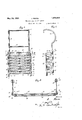
Another object is to provide aanovel construction which will permit the folding and unfolding of the parts with minimum hie tion. 7 r a The more specific objects and advantages will become apparent from a consideration of the description following taken in connection with accompanying drawings illustrat-i ing an operative embodiment. In said drawings Figure 1 is a view in front elevation showing the ladder in folded condition,
ladder in folded condition,
Figure 3 is a cross sectional view taken on the line 38 of Figure '1,
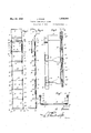
Figure 4: is a'front elevation showing the ladder extended, 1
Figure 5 is a side elevation showing the ladder extended, M
Figure 6 is an enlarged sectional view taken on the line 6-6 of Figure 4, and
- Figure 7 is an enlarged sectionalview taken on the line 77 of Figure 4:. y
Referring specifically to the drawings, a rigid frame is provided as at 10' which consists of a U-shaped bracket 11 at the top, and depending bars 12, rigidly riveted or otherwise connected therewith as at 13.
A suspending hook device is provided at 14 adapted to engage over a window sill or the like which may comprise two side or hookmembers 15 connected by cross bars 16 and pivoted by a rod 17 to clips 18, fastened to the bracket 11.
A multiplicity of rungs are employed as at 19, which are of U-shape as best shown in ,Figure 3, and at their terminals have balls 22 are pivoted at 24 to the leaves '18. "As a retended.
I pivoted thereon, constitutingfiheadsl 'The I i 7 bars 12 are hollow or ofgchannel form and have constricted entrance slots at"21,whereby the balls, which are of, greater diameter than the width of the slots 21, cannot be later-- ally withdrawn therefrom. I H Lazy tong links or'levers 22 arepivoted together at 28 and at their-outer ends are pivoted at 24,'to the rungs. The uppermost links :(il: sult, the rungs may extend, by gravity, from I the position shown in Figure l'to that shown in Figures 4 and 5 with the links 22 limit ing the relative movement of the rungs. It
' wil'l be realized that most of the rungs disen gage the side bars 12- when the ladder is ex- Normally-the parts are held in the folded or compact relation shown in Figures 1 and 2 by means of'llatch bars 25 pivoted at 26 to 7c the side ofthe lowermost rung and which latch bars have slots 27 adapted for engagement with buttons 28' car'ried bythe sidesof" r the bracket 11. When thelatch'bars 25 are Figure 2 is a side elevation showingthe 5. Obviously after use, the ladder may be I V folded back into the position shown in F ig- 'so V ures 1 and 2 and secured in that position by reengaging the latches 25 with buttons 28. Also it will be realized that the hook means 14 may be folded compactly with respect to the remainder of the structure tooccupy'mini 86 mum space when not in use. i p
Various changes may be resorted to pro vided they fall within the spirit and scope of the invention. L f I claim as my invention i V 1. A ladderof the class described comprising' a bracket, bars extending therefrom of channeled form having restricted openings, rungs having enlarged terminals engageable in the channels of the bars and prevented from lateral disengagement therefrom, and
link means pivoted together and to the rungs channeled form having restricted openings, I rungs having terminals with enlargements 'thereon engageable in the channels of the bars and prevented from lateral disengagement therefrom, link means connecting the rungs and' adapted to limit their opening movement, said enlargements constituting friction reducingmeans on the terminals of said rungs and within said channels, and 10 latch means securing the rungs in the bars 7 against extending movement. 1 '3. A ladder of the class described comprising a bracket, bars extending therefrom of channeled formhaving restricted openings, 15 rungs having terminals with enlargements thereon engageable in the channels of the,
bars and prevented from lateral disengagement therefrom, link means connecting the V rungs and adapted to limit their opening rmovements, said enlargements constituting' friction reducing means on the terminals of said rungs andwithin said channels, latch means securing therungs in the bars against extending movement, clips secured to said bracket, and suspending means attached to the clips, the uppermost links being attached to said. clips.
4. A ladder of the class described comprising a bracket, hollow/bars depending from so the bracket, rungs substantiallyof U-shape 7 having their terminals engaged in the hollows of the bars in folded condition links pivoted together and to said rungs, clips secured to said bracket, the uppermost links be- 7 x5 ing pivoted to said clips, suspending means connected to said clips, said links serving to limit the opening movement of the rungs, a latch pivoted to the lowermost rung, and a ,button on said bracket engageable by the ;40:latch to maintain the rungs and links in fold- L ed relation. I V 4 In testimony whereof I afiix my signature.
JOHN REESE.
i V V V 1,859,984
Priority Applications (1)
| Application Number | Priority Date | Filing Date | Title |
|---|---|---|---|
| US485989A US1859984A (en) | 1930-10-02 | 1930-10-02 | Folding fire escape ladder |
Applications Claiming Priority (1)
| Application Number | Priority Date | Filing Date | Title |
|---|---|---|---|
| US485989A US1859984A (en) | 1930-10-02 | 1930-10-02 | Folding fire escape ladder |
Publications (1)
| Publication Number | Publication Date |
|---|---|
| US1859984A true US1859984A (en) | 1932-05-24 |
Family
ID=23930179
Family Applications (1)
| Application Number | Title | Priority Date | Filing Date |
|---|---|---|---|
| US485989A Expired - Lifetime US1859984A (en) | 1930-10-02 | 1930-10-02 | Folding fire escape ladder |
Country Status (1)
| Country | Link |
|---|---|
| US (1) | US1859984A (en) |
Cited By (6)
| Publication number | Priority date | Publication date | Assignee | Title |
|---|---|---|---|---|
| US2993561A (en) * | 1959-08-13 | 1961-07-25 | Cyril J Watson | Collapsible ladder |
| US4751982A (en) * | 1987-06-04 | 1988-06-21 | Nicholas Wolfe | Foldable ladder |
| USD370736S (en) | 1994-08-12 | 1996-06-11 | Brk Brands, Inc. | Escape ladder |
| USD371854S (en) | 1994-08-12 | 1996-07-16 | Brk Brands, Inc. | Ladder rung |
| US5605205A (en) * | 1994-08-12 | 1997-02-25 | Brk Brands, Inc. | Readily deployable portable escape ladder |
| JP2017508513A (en) * | 2014-02-13 | 2017-03-30 | プロ パフォーマンス スポーツ,エル.エル.シー. | Agility ladder |
-
1930
- 1930-10-02 US US485989A patent/US1859984A/en not_active Expired - Lifetime
Cited By (7)
| Publication number | Priority date | Publication date | Assignee | Title |
|---|---|---|---|---|
| US2993561A (en) * | 1959-08-13 | 1961-07-25 | Cyril J Watson | Collapsible ladder |
| US4751982A (en) * | 1987-06-04 | 1988-06-21 | Nicholas Wolfe | Foldable ladder |
| USD370736S (en) | 1994-08-12 | 1996-06-11 | Brk Brands, Inc. | Escape ladder |
| USD371854S (en) | 1994-08-12 | 1996-07-16 | Brk Brands, Inc. | Ladder rung |
| US5605205A (en) * | 1994-08-12 | 1997-02-25 | Brk Brands, Inc. | Readily deployable portable escape ladder |
| JP2017508513A (en) * | 2014-02-13 | 2017-03-30 | プロ パフォーマンス スポーツ,エル.エル.シー. | Agility ladder |
| US20170246523A1 (en) * | 2014-02-13 | 2017-08-31 | Pro Performance Sports, L.L.C. | Agility ladder |
Similar Documents
| Publication | Publication Date | Title |
|---|---|---|
| US3012626A (en) | Emergency escape ladders | |
| US1859984A (en) | Folding fire escape ladder | |
| US1916208A (en) | Extension ladder | |
| US1897810A (en) | Window scaffold | |
| US3269485A (en) | Convertible ladder | |
| US666566A (en) | Collapsible ladder for berths. | |
| US3861499A (en) | Folding ladder | |
| US3208553A (en) | Folding ladder | |
| US3946834A (en) | Self storing fire escape ladder | |
| US2607523A (en) | Flexible ladder | |
| US1359297A (en) | Stepladder | |
| US1644739A (en) | Emergency ladder | |
| US4260039A (en) | Folding, collapsible ladder assembly | |
| US280527A (en) | Ttames h | |
| US877363A (en) | Fire-escape. | |
| US1647915A (en) | Ladder | |
| US1065166A (en) | Folding ladder. | |
| US258186A (en) | wintees | |
| US738164A (en) | Fire-escape. | |
| US2998863A (en) | Fire escape ladders | |
| US1546399A (en) | Fire life net | |
| US2509206A (en) | Stepladder | |
| US191762A (en) | Improvement in fire-escapes | |
| US260245A (en) | Diedeich schmidt | |
| US1102461A (en) | Fire-escape ladder. |