US1859958A - Mixing tool - Google Patents
Mixing tool Download PDFInfo
- Publication number
- US1859958A US1859958A US489128A US48912830A US1859958A US 1859958 A US1859958 A US 1859958A US 489128 A US489128 A US 489128A US 48912830 A US48912830 A US 48912830A US 1859958 A US1859958 A US 1859958A
- Authority
- US
- United States
- Prior art keywords
- members
- extending
- downwardly
- handle member
- flour
- Prior art date
- Legal status (The legal status is an assumption and is not a legal conclusion. Google has not performed a legal analysis and makes no representation as to the accuracy of the status listed.)
- Expired - Lifetime
Links
- 235000013312 flour Nutrition 0.000 description 16
- 238000000034 method Methods 0.000 description 6
- 238000010276 construction Methods 0.000 description 5
- 239000000463 material Substances 0.000 description 5
- 206010039509 Scab Diseases 0.000 description 2
- 239000002184 metal Substances 0.000 description 2
- 238000004519 manufacturing process Methods 0.000 description 1
- 235000014594 pastries Nutrition 0.000 description 1
Images
Classifications
-
- A—HUMAN NECESSITIES
- A47—FURNITURE; DOMESTIC ARTICLES OR APPLIANCES; COFFEE MILLS; SPICE MILLS; SUCTION CLEANERS IN GENERAL
- A47J—KITCHEN EQUIPMENT; COFFEE MILLS; SPICE MILLS; APPARATUS FOR MAKING BEVERAGES
- A47J43/00—Implements for preparing or holding food, not provided for in other groups of this subclass
- A47J43/10—Egg-whisks; Cream-beaters, i.e. hand implements or hand-driven devices
- A47J43/1087—Whisks or similar tools comprising mixing wires
Definitions
- MIXING TOOL Filed Oct. 16, 1930 gwoemtoz 3 condition.
- the principal object of thisinvention' is complished to provide a device for the successful 1nixing of flour and lard orlike, as required in the process of making certain edibles-such as pie crusts and pastries.
- a further object of this invention is to provide a 'manually operated device that will thoroughly mix flour and lard, one with'the other, ,withfgreat rapidity.
- a San further object of this invention is to provide a Hour and lard, or like, mixing tool that conforms to irregular-outlines of the Walls and bottom of the receptacle hold- I ing the material to be mixed, therehyassuring the successful mix tents in the receptacle.
- a still further object of my invention is to provide a lard and flour mixing tool that holds the cutting and mixing wires in a taut
- a still further object of this device is to provide a flour and lard mixing device that does not become clogged or fouled with the material to be commingled during the mixing process.
- VI I I A still further object of my invention to provide a flour and lard mixing tool that is economical in manufacture and durable. in use.
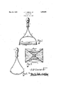
- Fig. 1 is a side view of'my complete in- Fig.2 is an end view of the device.
- Fig.3 is a bottom view of the invention II I I I ng the-mix ng process. taut holding of ⁇ the wires 13 is encouraged by the oonstruction of the loop members 11 and 12, i; e., their J and more fully illustrates its construction- The mixing of flour and lardis a very difiicult task and must be'most successfully ajc- I realize excellent pie crust or like.
- a still further object of my invention is to provide a manually operated flour and lard ing of all of the coni Imember are two cutting and mixing Wires .tion as shown in Fig. 2. As shown in the metal to successfullyhold the cutting and if the housewife or cook is to The ,ap-
- each of loop co'nstructionl' ' Thesetwo loop members extend downwardly and outwardly away from each other for the greater portion oftheir upperlengthsand then extend-sharp-. I 1y downwardly and-only slightly outwardly.
- the extreme bottom or center portion of'eajch of the loopmembers is of Tcircularconstrum" drawings the lower ends of the loop members 11 and 12 Will be a considerable distance apart. It is between these two, center curved portions of the loop members that the. cutting and mixing wires 13 extend.
- Thesewires n V V :13 are very small in diameter and are each My inventlon conslsts 1n the construction,
- the holdingandsupportingmem bers'll and 12 should be ofsuitable spring mixing wires 13 tightly between-them durs V M lower portions extending downwardly and and the lower end of the invention meets resistance, the tendency of the lower ends of r the device-willbe'to spread apart frbm each other, thereby tightening the wires 13.
- numeral 14 designates two bracesfbetwe'en the two members 11 and.:12 7
- the l oweriend of the invem tion will conformto odd shaped'vessels hold ing'the flour and lard to be mixed and also makes itposs'ible to easily scrape and out any 7 of the lard or flour that clings to theinside wall or walls of the vessel's.
- handle member; two duplicateone-piece-loop members of spring .metalkextendingrfrom said handle member; said: two: lbop: members ex tending.- downwardly and? outwardly away from. eachother and then sharply down wardly and outwardly at. their lower portions in order'- that when said rhandle',
- loop members meet resistance, their tendency will be to spring apart, andla 'plurality ofi small to the lower portions of said loop members.
- a handle member two duplicate one-piece loop members of spring metal extending from said handle member; said two loop members ex tending, downwardly and outwardly away from each other and thensharply downwardand outwardly at their lower portions in order that when said 7 handle member is pushed? downwardly and said loop members meet resistance, their tendency will be to spring apart, a plurality of small flexible wires extending between and secured to the lower" portions of said loop members, and brace. members secured-to and. between: said loop members c a 7 3L
- a.handleamember two; duplicate one-piece l'oop members extending from said handle mem-- ber. and having their endtportions entering arcommonbore in said handle member ,said
- said handle member and then extending membersmeetresistance their tendency. will be to spread apart from. each other, andfi'a plurality of small .wires extending-between and securedtothe lower portionsof said loop members.
- handle member two duplicate; one-piece loop.
- a handle member two duplicate one-piece supporting members extending from said handlemember; said supporting members extending first downwardly and outwardly away from said handle member and away from each 7 other and then extending sharply downward ly and outwardly attheir lower portions in order that when said handle member is pushed downwardly and said supporting members meet resistance their tendency will be to spread apart, and a plurality of fine cutting and mixing wires secured to and extending. between said two'supporting members. y I a 8.
- a handle member two duplicate V one-piece loop members extending from said handlelmember and having their end portions entering a common bore in said'handle member and 7 their central'portions each forming a downwardly extending curve; said two loop members first extending downwardly and outwardly away from each other and said handle member and then extending sharply downwardly --and outwardly at their lower portions in order that when said handle member is pushed downwardly and said loop members meet resistance their tendency will be to spread apart-from each'other, and a plurality of small parallel wires extending between and secured to the lower central portions of said loop, members.
Landscapes
- Engineering & Computer Science (AREA)
- Mechanical Engineering (AREA)
- Food Science & Technology (AREA)
- Food-Manufacturing Devices (AREA)
Description
y 1932- I J. T. CESSNA, JR 1,859,958
MIXING TOOL Filed Oct. 16, 1930 gwoemtoz 3 condition.
vention ready for use.
Patented May 24, 1932 I .MIXINGI roon TM Applicatiohiiled October 1e,- 19:50. serial no. 489,128.
- The principal object of thisinvention' is complished to provide a device for the successful 1nixing of flour and lard orlike, as required in the process of making certain edibles-such as pie crusts and pastries.
j A further object of this invention is to provide a 'manually operated device that will thoroughly mix flour and lard, one with'the other, ,withfgreat rapidity. A.
A San further object of this inventionis to provide a Hour and lard, or like, mixing tool that conforms to irregular-outlines of the Walls and bottom of the receptacle hold- I ing the material to be mixed, therehyassuring the successful mix tents in the receptacle. I I
A still further object of my invention is to provide a lard and flour mixing tool that holds the cutting and mixing wires in a taut A still further object of this device is to provide a flour and lard mixing device that does not become clogged or fouled with the material to be commingled during the mixing process. VI I I A still further object of my invention to provide a flour and lard mixing tool that is economical in manufacture and durable. in use.
These and other objects will be apparent to those skilled in the art.
arrangement and combination-of the various parts of the device, whereby the ob ects con templated are attained as "hereinafter more fully set forth, pointed out in myclaims and i'llu'stratedin the accompanying drawings, in which: Fig. 1 is a side view of'my complete in- Fig.2 is an end view of the device.
' Fig.3 is a bottom view of the invention II I I I ng the-mix ng process. taut holding of {the wires 13 is encouraged by the oonstruction of the loop members 11 and 12, i; e., their J and more fully illustrates its construction- The mixing of flour and lardis a very difiicult task and must be'most successfully ajc- I realize excellent pie crust or like.
proved method byndomestic science I I tors is'to cut,;the lard 'into' the flour with a knife. slow andutiresome.
A still further object of my invention is to provide a manually operated flour and lard ing of all of the coni Imember are two cutting and mixing Wires .tion as shown in Fig. 2. As shown in the metal to successfullyhold the cutting and if the housewife or cook is to The ,ap-
instruc- This procedure, of course, [is "very 55 I The objections to' tools now on the market to supersede the'slow knife method of mixing the flour and lard are theirlinability to .easilycut through the material to be mixed, due to their heavy. cutting members, their inability to maintain the cutting members in taut 'condition'and in proper relation one to'Q th-e other, the difficulty in keeping themfina sanitary condiame d theirtendency to clog and improperly function I have overcome such objections as will, hereinafter. be appreciated. I have used the numeral 10 to designate the handle member of the invention. I
Extending downwardly from this handle each of loop co'nstructionl' 'Thesetwo loop members extend downwardly and outwardly away from each other for the greater portion oftheir upperlengthsand then extend-sharp-. I 1y downwardly and-only slightly outwardly. The extreme bottom or center portion of'eajch of the loopmembers is of Tcircularconstrum" drawings the lower ends of the loop members 11 and 12 Will be a considerable distance apart. It is between these two, center curved portions of the loop members that the. cutting and mixing wires 13 extend. Thesewires n V V :13 are very small in diameter and are each My inventlon conslsts 1n the construction,
I the other. -The holdingandsupportingmem bers'll and 12 should be ofsuitable spring mixing wires 13 tightly between-them durs V M lower portions extending downwardly and and the lower end of the invention meets resistance, the tendency of the lower ends of r the device-willbe'to spread apart frbm each other, thereby tightening the wires 13. The
To mix the flour and lard the same should be placed in a receptacle and my invention grasped by the handle 10 and manually Vforced downwardly and upwardly, in and" through the lardand flour. Due: to;the. construction inmy invention permitting very fine cutting andmlxmg" wires 1-3,,the lbwer end of the invention will easilycuti through the material to be mixed with a-v minimum amount of effort expended and without undesirable clogging or fouling with thematerial to be mixed as experienced with mixershaving cutting member sot heavy construction. As the cuttingJandKmixing,wires 7 easily pass completely throughztlie flour and lard at each down or upward movement of the handle 10, the lard' and flour: will not only be successfully mixed butwill be thoroughly mixed in a very short durationof time;
y m akingthe lower ends-ofthe loop members 11' and 1'2curved, the l oweriend of the invem tion will conformto odd shaped'vessels hold ing'the flour and lard to be mixed and also makes itposs'ible to easily scrape and out any 7 of the lard or flour that clings to theinside wall or walls of the vessel's.
Although I have described" my invention as particularly adapted to the mixing of lard and flour, it be used-to equal ad} vantage for the mixingof other materials.
By the construction of my invention as above disclosed it is easily and quickly washed andmaintained in a sanitary condition.
Some changes may be made in the construction and arrangement off my improved mixingtoolwithout departing from the real spirit'and purpose ofmyi nvention, and it is my intention to cover bymy claimsany modifie'd forms ofstructure' or useof'm'echanical equivalents which may be reasonably included within their scope'.
I claim z- 11in; a device of'the class described; a
handle: member; two duplicateone-piece-loop members of spring .metalkextendingrfrom said handle member; said: two: lbop: members ex tending.- downwardly and? outwardly away from. eachother and then sharply down wardly and outwardly at. their lower portions in order'- that when said rhandle',
member is pushedidownwa-rdly and said." loop members meet resistance, their tendency will be to spring apart, andla 'plurality ofi small to the lower portions of said loop members.
2. In a device of the class described, a handle member two duplicate one-piece loop members of spring metal extending from said handle member; said two loop members ex tending, downwardly and outwardly away from each other and thensharply downwardand outwardly at their lower portions in order that when said 7 handle member is pushed? downwardly and said loop members meet resistance, their tendency will be to spring apart, a plurality of small flexible wires extending between and secured to the lower" portions of said loop members, and brace. members secured-to and. between: said loop members c a 7 3L In adevice of the class described, a.handleamember, two; duplicate one-piece l'oop members extending from said handle mem-- ber. and having their endtportions entering arcommonbore in said handle member ,said
twoloop members first extending d ownwardly and outwardly away from each: other. and
said handle member and then extending membersmeetresistance their tendency. will be to spread apart from. each other, andfi'a plurality of small .wires extending-between and securedtothe lower portionsof said loop members. i
4.. In a deviceofthe classdescribed,.averti cal handle member, two duplicate one-piece loop members having their end portions'ses cured to the lower end: of said handle mem ber; saidtwo'loop members firstextending downwardly and outwardly away from. each other and said handle member and then exe tending: sharply downwardly and. outwardly at their lower' portions in order that y when said. handle member is pushed downwardly andisaid loopvmembers meet resistance their tendency willbe to spread apart. fromeach other," and a plurality of smallawires 'extending between andlsecured to the lower: portions of said loopmembers/ c 5'. In a device of the class described, a ban? dle member, two duplicatev one-piece loop members extending independently; and, free 7 of each other from saidihandle member; said two loop members firstextending downwardly and outwardly away from eachother and i said handle member and then extending sharply downwardly. and outwardly at their 7 lower portions in order that when said han dle member is pushed downwardly and: said loop members meet resistance their tendency will be to spread apart fromieachiother,- andmembers.
6. In a device of the class described, a I
handle member, two duplicate; one-piece loop.
members having their end portionssecured to said handle member and extending free and independentlyof each other downwardly and outwardly away from said handle'and away from each other, and a plurality of cutting wires extending between and secured to the lower portions of said loop members.
7. In a device of the class described, a handle member, two duplicate one-piece supporting members extending from said handlemember; said supporting members extending first downwardly and outwardly away from said handle member and away from each 7 other and then extending sharply downward ly and outwardly attheir lower portions in order that when said handle member is pushed downwardly and said supporting members meet resistance their tendency will be to spread apart, and a plurality of fine cutting and mixing wires secured to and extending. between said two'supporting members. y I a 8. In a device of the class described,.a handle member, two duplicate V one-piece loop members extending from said handlelmember and having their end portions entering a common bore in said'handle member and 7 their central'portions each forming a downwardly extending curve; said two loop members first extending downwardly and outwardly away from each other and said handle member and then extending sharply downwardly --and outwardly at their lower portions in order that when said handle member is pushed downwardly and said loop members meet resistance their tendency will be to spread apart-from each'other, and a plurality of small parallel wires extending between and secured to the lower central portions of said loop, members.
JOHN T. CESSNA, JR;-
Priority Applications (1)
| Application Number | Priority Date | Filing Date | Title |
|---|---|---|---|
| US489128A US1859958A (en) | 1930-10-16 | 1930-10-16 | Mixing tool |
Applications Claiming Priority (1)
| Application Number | Priority Date | Filing Date | Title |
|---|---|---|---|
| US489128A US1859958A (en) | 1930-10-16 | 1930-10-16 | Mixing tool |
Publications (1)
| Publication Number | Publication Date |
|---|---|
| US1859958A true US1859958A (en) | 1932-05-24 |
Family
ID=23942523
Family Applications (1)
| Application Number | Title | Priority Date | Filing Date |
|---|---|---|---|
| US489128A Expired - Lifetime US1859958A (en) | 1930-10-16 | 1930-10-16 | Mixing tool |
Country Status (1)
| Country | Link |
|---|---|
| US (1) | US1859958A (en) |
Cited By (4)
| Publication number | Priority date | Publication date | Assignee | Title |
|---|---|---|---|---|
| US20040188555A1 (en) * | 2003-03-26 | 2004-09-30 | Galante Gregory B. | Pastry blender and cooked fruit and vegetable masher |
| US20060113413A1 (en) * | 2003-03-26 | 2006-06-01 | Kitchen Innovations Inc. | Pastry blender and cooked fruit and vegetable masher |
| GB2436302A (en) * | 2006-03-23 | 2007-09-26 | Maxpat Trading & Marketing | Culinary utensil |
| US20120074252A1 (en) * | 2010-09-23 | 2012-03-29 | Progressive International Corporation | Dough blender |
-
1930
- 1930-10-16 US US489128A patent/US1859958A/en not_active Expired - Lifetime
Cited By (10)
| Publication number | Priority date | Publication date | Assignee | Title |
|---|---|---|---|---|
| US20040188555A1 (en) * | 2003-03-26 | 2004-09-30 | Galante Gregory B. | Pastry blender and cooked fruit and vegetable masher |
| US7007876B2 (en) | 2003-03-26 | 2006-03-07 | Galante Gregory B | Pastry blender and cooked fruit and vegetable masher |
| US20060113413A1 (en) * | 2003-03-26 | 2006-06-01 | Kitchen Innovations Inc. | Pastry blender and cooked fruit and vegetable masher |
| US7455253B2 (en) | 2003-03-26 | 2008-11-25 | Kitchen Innovations Inc. | Pastry blender and cooked fruit and vegetable masher |
| GB2436302A (en) * | 2006-03-23 | 2007-09-26 | Maxpat Trading & Marketing | Culinary utensil |
| US20070221772A1 (en) * | 2006-03-23 | 2007-09-27 | Maxpat Trading & Marketing (Far East) Limited | Culinary utensil |
| US7748889B2 (en) | 2006-03-23 | 2010-07-06 | Maxpat Trading & Marketing (Far East) Limited | Culinary utensil |
| GB2436302B (en) * | 2006-03-23 | 2011-04-13 | Maxpat Trading & Marketing | Culinary Utensil |
| US20120074252A1 (en) * | 2010-09-23 | 2012-03-29 | Progressive International Corporation | Dough blender |
| US8851738B2 (en) * | 2010-09-23 | 2014-10-07 | Progressive International Corporation | Dough blender with scraper |
Similar Documents
| Publication | Publication Date | Title |
|---|---|---|
| US1859958A (en) | Mixing tool | |
| US2770877A (en) | Combination can opener and measuring cup | |
| US1919006A (en) | Dough blender | |
| US1020865A (en) | Cutter. | |
| US1517624A (en) | Combination fruit crusher and flour sifter | |
| US2712177A (en) | Can openers | |
| US1657299A (en) | Pastry-forming device | |
| US2614484A (en) | Retainer for vegetables and like products while cooking the same | |
| US2524116A (en) | Mixing bowl scraper | |
| US2058925A (en) | Adjustable can opener and funnel | |
| US920484A (en) | Dough-mixer. | |
| US403522A (en) | Scraper or cleaner | |
| CN208957858U (en) | A kind of convenient egg breaker | |
| US1654965A (en) | Stirring spoon | |
| US1636240A (en) | Strainer | |
| US1878956A (en) | Can perforator | |
| US1085337A (en) | Churn. | |
| US1843806A (en) | Can opener | |
| US53429A (en) | Improved egg-beater | |
| US1611380A (en) | Meat-loaf former | |
| DE803238C (en) | Device for portioning semi-solid masses | |
| US1542574A (en) | Porridge mixer | |
| US218578A (en) | Improvement in devices for kneading dough and working butter | |
| US1515930A (en) | Flour sifter | |
| US1938807A (en) | Lidding tool |