US1859930A - Recording and reproduction of intelligence - Google Patents
Recording and reproduction of intelligence Download PDFInfo
- Publication number
- US1859930A US1859930A US484490A US48449030A US1859930A US 1859930 A US1859930 A US 1859930A US 484490 A US484490 A US 484490A US 48449030 A US48449030 A US 48449030A US 1859930 A US1859930 A US 1859930A
- Authority
- US
- United States
- Prior art keywords
- current
- blank
- motor
- record
- armature
- Prior art date
- Legal status (The legal status is an assumption and is not a legal conclusion. Google has not performed a legal analysis and makes no representation as to the accuracy of the status listed.)
- Expired - Lifetime
Links
Images
Classifications
-
- G—PHYSICS
- G11—INFORMATION STORAGE
- G11B—INFORMATION STORAGE BASED ON RELATIVE MOVEMENT BETWEEN RECORD CARRIER AND TRANSDUCER
- G11B11/00—Recording on or reproducing from the same record carrier wherein for these two operations the methods are covered by different main groups of groups G11B3/00 - G11B7/00 or by different subgroups of group G11B9/00; Record carriers therefor
Definitions
- This invention relates to the recording of intelligence and particularly to apparatus for making a permanent record of spoken words.
- the objects are to secure in permanent form a record of speech or other intelligence which may be reproduced indefinitely without deterioration, to simplify the making of such records, to improve the faithfulness of reproduction, and to otherwlse improve apparatus of this character.
- a photographic film is first prepared with a record of the desired speech.
- the film thus prepared is drivenin synchronism with a blank armature disc of soft iron or permalloy, the film serving to control the flow of current in a photoelectric system, and theyarymg current serving to govern a cutting tool which mills the edge of the armature blank to form a contour which is a faithful representation of the speech recorded on the photographic film.
- Fig. 1 shows a system for cutting an armature blank in accordance with this invention
- Fig. 2 is a modification of a portion of the circuit shown in Fig. 1
- 3 and 4 are front and side views of an electromagnetic machine employing an armature shaped in accordance with this invention.
- a photographic film 1 having been prepared in any suitable manner, is placed on the drum 2 which is carried on a shaft 3.
- a blank or disc 4 of electromagnetic material is also secured to the shaft 3 for rotation in synchronism with the drum 2;
- the shaft 3 is driven by a motor M through gears 7 and 8 with a suitable reduction gearing 6 interposed.
- a photoelectric system comprising a source of light 9, lenses 10 and 11, and a photoelec-
- the other terminal of the resistance 16 is connected to a voltmeter relay 21, and the voltmeter relay in turn is connected to the movable contact 19.
- the contact 19 is carried on an armature shaft 20, which, through gears 24 and 25, is driven by the motor M1.
- the motor Ml has its shaft 27 geared to a control shaft 29 through the worm gears 28.
- the control shaft 29 engages a carriage which carries a milling cutter 32 and its driving mo-, tor M2.
- the motor Ml is capable of rotating in either direction, and, according to the direction of rotation of the shafts 27 and 29, the carrier 31 moves toward or away from the armature blank 4 to vary the depth to which the cutter 32 cuts the periphery of said blank.
- the operation of the device will now be explained.
- the photographic film 1, carrying a record of speech or other sound, is secured on the drum 2, and a blank armature disc 1 is secured to the shaft 3.
- the motor M is driven at a suitable speed to insure a faithful response of the control mechanism to the photoelectric currents and the corresponding accurate cutting by the miller 32 of the periphery of the blank.
- the photoelectric currents set up in the circuit 13 are impressed upon the amplifier A and in turn cause a variable flow of current from the source 15 through the resistance 16 in the plate circuit. This causes a variable potential across the resistance 16 which at every instant is a correct representation of the record on the film.
- the voltmeter relay 21 remains inert, and the field circuit of the motor M1 remains open. As soon, however, as the potential across the resistance 16 varies in either direction, current flows through the voltmeter relay 21 and the relay attracts its armature to close either one or the other of its contacts, depending upon whether the potential across the resistance 16 is greater or less than that across the resistance 18.
- the relay 21 closes a circuit for one of the field windings 23 of the motor so that current flowing from the source 26 causes the motor M1 to rotate in such a direction as to advance the movable contact 19 to the point on the resistance 18 where it balances the potential across the resistance 16 permitting relay 21 to release and the motor to again come to rest.
- the motor M1 adjusts the potentiometer contact 19, it also adjustts the position of the milling cutter 32 so that the edge of the blank formed during this process presents a correct representation of the sound record on the film 1.
- the voltmeter relay 21 instead of controlling the motor M3 directly as in Fig. 1, operates a relay 35 instead.
- the relay 35 when operated reverses the direction of current to the armature winding of the motor M3. This causes the motor to reverse its direction of rotation advancing the contact 19 to the point where the voltmeter relay 21 releases.
- Relay 21 releasing releases the relay 35 which again reverses the motor M3. and the contact 19 is now shifted to a point Where the relay 21 again operates. In this manner the contact 19 is continuously hunting, assuming the potential across the resistance 16 remains constant. This method of control permits the contact 19 to more readily follow slight variations of potential across the resistance 16.
- Figs. 3 and 4 disclose a portion of an electromagnetic machine employing a shaped armature disc.
- the shaped armature 4 which may be a separate part and attached to the body of the disc 40 as illustrated, is arranged to rotate between the pole-pieces 42 and 43 of a U-shaped magnet 41.
- Pole-pieces 42 and 43 carry the pick-up windings '44 and 45.
- An energizing coil 46 is wound on the upper portion of the U-shaped magnet 41.
- the armature 4 As the disc 40 rotates, the armature 4 with its irregular shaped periphery varies the magnetic resistance between the pole pieces 42 and 43, thus causing a variation in the field strength and thereby inducing in the pick-up coils 44 and 45 an electric current which is a correct representation of the sound originally recorded on the hotographic film 1.
- This current may be amplified in any suitable manner and applied to a receiving device.
- a medium having a record of intelligence thereon, a source of current, means controlled by said medium for varying the flow of current from said source in accordance with said record, a blank of magnetic material, and means automatically controlled by said current for cut-ting away a portion of said blank to form a contour which represents the variations of flow of said current.
- a medium on which is recorded a speech record a source of current, means controlled by said medium for varying the intensity of current flowing from said source, a disc 01 n'iagnetic material, a cutting tool, means for moving said cutting tool toward and away from the periphery of said disc, and current responsive means for controlling the amount of movement imparted to said cutting tool in accordance with the variation of intensity of said current.
- a photographic film having a speech record thereon, a source of current, a photoelectric system including a source of light and a photoelectric cell for varying the flow of current from said source in accordance with the speech record, a disc of magnetic material, means for rotating said disc, a rotary cutting tool and means for rotating the same, means for moving said cutting tool toward and away from the pcriphery of said disc to vary the depth of the cut made in said disc, and means for automatically controlling the movement of said cutting tool in accordance with the variation of said current.
- the combination in a recording system of a medium having a speech record thereon anarmature blank, means for rotating said blank, a milling machine movable toward and away from the periphery of said blank to cut away irregular portions thereof as the blank rotates, a motor for driving said milling machine, a second motor for moving said milling machine toward and away from the periphery of said blank, a source of current, means for varying the flow of current from said source in accordance with the record on said medium, and means for controlling the direction of rotation of said second motor in accordance with the intensity of said current.
Landscapes
- Rotational Drive Of Disk (AREA)
Description
May 24, 1932. o. R. MILLER 1,859,930
RECORDING AND REPRODUCTION OF INTELLIGENCE Filed Sept. 26, 1930 ml Irm- FIELD WIND/N6 A TOPNEY Patented May 24, 1932 UNITED STATES PATENT OFFICE OHMER R. MILLER, OI FLORAL PARK, NEW YORK, ASSIGNOR TO BELL TELEPHONE LABO- RATORIES, INCORPORATED, 01' NEW YORK, N. Y., A CORPORATION OF NEW YORK RECORDING AND REPRODUCTION OF INTELLIGENCE Application filed September 26, 1980. Serial No. 484,490.
This invention relates to the recording of intelligence and particularly to apparatus for making a permanent record of spoken words.
The objects are to secure in permanent form a record of speech or other intelligence which may be reproduced indefinitely without deterioration, to simplify the making of such records, to improve the faithfulness of reproduction, and to otherwlse improve apparatus of this character.
In accordance with this invention, the foregoing objects are attained and a s mple, durable, and faithful record of intelligence is secured by shaping the periphery of the armature of an electromagnetic machine in such a manner that the contour of the armature thus prepared is an accurate representation of the speech or other intelligence recorded. To accomplish this, a photographic film is first prepared with a record of the desired speech. The film thus prepared is drivenin synchronism with a blank armature disc of soft iron or permalloy, the film serving to control the flow of current in a photoelectric system, and theyarymg current serving to govern a cutting tool which mills the edge of the armature blank to form a contour which is a faithful representation of the speech recorded on the photographic film.
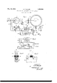
In the drawings, Fig. 1 shows a system for cutting an armature blank in accordance with this invention, Fig. 2 is a modification of a portion of the circuit shown in Fig. 1, and 3 and 4 are front and side views of an electromagnetic machine employing an armature shaped in accordance with this invention.
Referring to Fig. 1, a photographic film 1, having been prepared in any suitable manner, is placed on the drum 2 which is carried on a shaft 3. A blank or disc 4 of electromagnetic material is also secured to the shaft 3 for rotation in synchronism with the drum 2; The shaft 3 is driven by a motor M through gears 7 and 8 with a suitable reduction gearing 6 interposed.
A photoelectric systemcomprising a source of light 9, lenses 10 and 11, and a photoelec- The other terminal of the resistance 16 is connected to a voltmeter relay 21, and the voltmeter relay in turn is connected to the movable contact 19. The contact 19 is carried on an armature shaft 20, which, through gears 24 and 25, is driven by the motor M1.
The motor Ml has its shaft 27 geared to a control shaft 29 through the worm gears 28. The control shaft 29 engages a carriage which carries a milling cutter 32 and its driving mo-, tor M2. The motor Ml is capable of rotating in either direction, and, according to the direction of rotation of the shafts 27 and 29, the carrier 31 moves toward or away from the armature blank 4 to vary the depth to which the cutter 32 cuts the periphery of said blank.
The operation of the device will now be explained. The photographic film 1, carrying a record of speech or other sound, is secured on the drum 2, and a blank armature disc 1 is secured to the shaft 3. The motor M is driven at a suitable speed to insure a faithful response of the control mechanism to the photoelectric currents and the corresponding accurate cutting by the miller 32 of the periphery of the blank. The photoelectric currents set up in the circuit 13 are impressed upon the amplifier A and in turn cause a variable flow of current from the source 15 through the resistance 16 in the plate circuit. This causes a variable potential across the resistance 16 which at every instant is a correct representation of the record on the film. As long as the potential across the left-hand portion of the resistance 18 of the potentiometer 17 is sufficient to balance the potential across the resistance 16, the voltmeter relay 21 remains inert, and the field circuit of the motor M1 remains open. As soon, however, as the potential across the resistance 16 varies in either direction, current flows through the voltmeter relay 21 and the relay attracts its armature to close either one or the other of its contacts, depending upon whether the potential across the resistance 16 is greater or less than that across the resistance 18. In any event, the relay 21 closes a circuit for one of the field windings 23 of the motor so that current flowing from the source 26 causes the motor M1 to rotate in such a direction as to advance the movable contact 19 to the point on the resistance 18 where it balances the potential across the resistance 16 permitting relay 21 to release and the motor to again come to rest. As the motor M1 adjusts the potentiometer contact 19, it also adusts the position of the milling cutter 32 so that the edge of the blank formed during this process presents a correct representation of the sound record on the film 1. This process continues, the motor M1 rotating first in one direction and then the other according to the change of potential across resistance 16, until the complete record on the film 1 has been transferred in permanent form to the armature blank 4, which is to be used for an electromagnetic device for reproducing the sound indefinitely without deterio ration.
In the modification shown in Fig. 2, the voltmeter relay 21, instead of controlling the motor M3 directly as in Fig. 1, operates a relay 35 instead. The relay 35 when operated reverses the direction of current to the armature winding of the motor M3. This causes the motor to reverse its direction of rotation advancing the contact 19 to the point where the voltmeter relay 21 releases. Relay 21 releasing, releases the relay 35 which again reverses the motor M3. and the contact 19 is now shifted to a point Where the relay 21 again operates. In this manner the contact 19 is continuously hunting, assuming the potential across the resistance 16 remains constant. This method of control permits the contact 19 to more readily follow slight variations of potential across the resistance 16.
Figs. 3 and 4 disclose a portion of an electromagnetic machine employing a shaped armature disc. The shaped armature 4, which may be a separate part and attached to the body of the disc 40 as illustrated, is arranged to rotate between the pole-pieces 42 and 43 of a U-shaped magnet 41. Pole-pieces 42 and 43 carry the pick-up windings '44 and 45. An energizing coil 46 is wound on the upper portion of the U-shaped magnet 41. As the disc 40 rotates, the armature 4 with its irregular shaped periphery varies the magnetic resistance between the pole pieces 42 and 43, thus causing a variation in the field strength and thereby inducing in the pick- up coils 44 and 45 an electric current which is a correct representation of the sound originally recorded on the hotographic film 1. This current may be amplified in any suitable manner and applied to a receiving device.
What is claimed is:
1. In combination, a medium having a record of intelligence thereon, a source of current, means controlled by said medium for varying the flow of current from said source in accordance with said record, a blank of magnetic material, and means automatically controlled by said current for cut-ting away a portion of said blank to form a contour which represents the variations of flow of said current.
2. In con'ibination, a medium on which is recorded a speech record, a source of current, means controlled by said medium for varying the intensity of current flowing from said source, a disc 01 n'iagnetic material, a cutting tool, means for moving said cutting tool toward and away from the periphery of said disc, and current responsive means for controlling the amount of movement imparted to said cutting tool in accordance with the variation of intensity of said current.
3. In combination, a photographic film having a speech record thereon, a source of current, a photoelectric system including a source of light and a photoelectric cell for varying the flow of current from said source in accordance with the speech record, a disc of magnetic material, means for rotating said disc, a rotary cutting tool and means for rotating the same, means for moving said cutting tool toward and away from the pcriphery of said disc to vary the depth of the cut made in said disc, and means for automatically controlling the movement of said cutting tool in accordance with the variation of said current.
4. The combination in a recording system of a photographic film having a speech record thereon, an armature blank of magnetic material, a driving shaft for driving said film and blank in synchronism, a source of current, means including a photoelectric cell for varying the flow of current from said source in accordance with the record on said film. a milling machine for cutting away a portion of said armature blank, and means controlled by the flow of current from said source for varying the position of said milling machine such that the contour of the armature blank when milled is a representation of the record on said film.
The combination in a recording system of a medium having a speech record thereon. anarmature blank, means for rotating said blank, a milling machine movable toward and away from the periphery of said blank to cut away irregular portions thereof as the blank rotates, a motor for driving said milling machine, a second motor for moving said milling machine toward and away from the periphery of said blank, a source of current, means for varying the flow of current from said source in accordance with the record on said medium, and means for controlling the direction of rotation of said second motor in accordance with the intensity of said current.
6. The combination in a recording system of amedium having a speech record thereon, an armature blank. means for driving said medium and said blank in synchronism, a. rotary cutter for cutting away portions of the periphery of said blank to present an irregular contour. a motor for advancing said cutter to and from the periphery of said blank, a source of current, a potentiometer driven by said motor, means for varying the flow of current from said source in accordance with the speech record on said medium, and a relay controlled by said potentiometer, and in accordance with the intensity of current flowing from said source to control the direction of rotation of said motor.
In witness whereof, I hereunto subscribe my name this 22d day of September, 1930.
' OHMER R. MILLER.
Priority Applications (1)
| Application Number | Priority Date | Filing Date | Title |
|---|---|---|---|
| US484490A US1859930A (en) | 1930-09-26 | 1930-09-26 | Recording and reproduction of intelligence |
Applications Claiming Priority (1)
| Application Number | Priority Date | Filing Date | Title |
|---|---|---|---|
| US484490A US1859930A (en) | 1930-09-26 | 1930-09-26 | Recording and reproduction of intelligence |
Publications (1)
| Publication Number | Publication Date |
|---|---|
| US1859930A true US1859930A (en) | 1932-05-24 |
Family
ID=23924364
Family Applications (1)
| Application Number | Title | Priority Date | Filing Date |
|---|---|---|---|
| US484490A Expired - Lifetime US1859930A (en) | 1930-09-26 | 1930-09-26 | Recording and reproduction of intelligence |
Country Status (1)
| Country | Link |
|---|---|
| US (1) | US1859930A (en) |
Cited By (7)
| Publication number | Priority date | Publication date | Assignee | Title |
|---|---|---|---|---|
| US2595189A (en) * | 1950-03-31 | 1952-04-29 | Milton H Feig | Rheostat potentiometer |
| US2632061A (en) * | 1947-06-07 | 1953-03-17 | Brush Dev Co | Apparatus for producing variable width magnetic recordings |
| US2657296A (en) * | 1951-11-24 | 1953-10-27 | North American Aviation Inc | Potentiometer compensating machine |
| US2686282A (en) * | 1950-07-22 | 1954-08-10 | North American Aviation Inc | Shaft rotation function generator |
| US2906187A (en) * | 1954-01-07 | 1959-09-29 | Dotson Kimes Entpr | Automatic camera control |
| US3174722A (en) * | 1962-09-17 | 1965-03-23 | Erhard J Alm | Load lifting device |
| US3264452A (en) * | 1962-05-21 | 1966-08-02 | Packard Bell Electronics Corp | Data processing apparatus |
-
1930
- 1930-09-26 US US484490A patent/US1859930A/en not_active Expired - Lifetime
Cited By (7)
| Publication number | Priority date | Publication date | Assignee | Title |
|---|---|---|---|---|
| US2632061A (en) * | 1947-06-07 | 1953-03-17 | Brush Dev Co | Apparatus for producing variable width magnetic recordings |
| US2595189A (en) * | 1950-03-31 | 1952-04-29 | Milton H Feig | Rheostat potentiometer |
| US2686282A (en) * | 1950-07-22 | 1954-08-10 | North American Aviation Inc | Shaft rotation function generator |
| US2657296A (en) * | 1951-11-24 | 1953-10-27 | North American Aviation Inc | Potentiometer compensating machine |
| US2906187A (en) * | 1954-01-07 | 1959-09-29 | Dotson Kimes Entpr | Automatic camera control |
| US3264452A (en) * | 1962-05-21 | 1966-08-02 | Packard Bell Electronics Corp | Data processing apparatus |
| US3174722A (en) * | 1962-09-17 | 1965-03-23 | Erhard J Alm | Load lifting device |
Similar Documents
| Publication | Publication Date | Title |
|---|---|---|
| US1859930A (en) | Recording and reproduction of intelligence | |
| GB926614A (en) | Method and apparatus for winding wire and the like | |
| US2078357A (en) | Telegraphone apparatus and circuit | |
| US2038976A (en) | Sound record | |
| US2085582A (en) | Phonograph | |
| US1611089A (en) | Adjustment of magnetic tachometers | |
| EP0129475B1 (en) | Magnetic tachometer for disk drives | |
| JPS5718035A (en) | Optical recording and reproducing device | |
| US2462435A (en) | Apparatus for uninterrupted reproduction of disk phonographrecords | |
| US2003913A (en) | Position controlling device | |
| US1588706A (en) | Sound recording and reproducing device | |
| US2768242A (en) | Sound reproducing and recording apparatus | |
| US1950870A (en) | Recorder | |
| US2221312A (en) | Means adapted to reproduce sounds or other sensory effects | |
| US1877485A (en) | Sound recording and reproducing device | |
| US2697812A (en) | Automatic amplitude regulation in electrical transmission system and apparatus | |
| US1993616A (en) | Apparatus and method for recording sound accurately | |
| US1696303A (en) | Method of sound propagation | |
| US1836206A (en) | Method and apparatus for use in connection with the making of sound records | |
| US2203877A (en) | Telephone message recording and reproducing apparatus | |
| US2034111A (en) | Recording of oscillations on a carrier | |
| SU2492A1 (en) | Method of making sound plates | |
| US3964752A (en) | Methods and devices for recording, engraving and reproducing modulated information in tetraphony | |
| US2535657A (en) | Sound recording system | |
| US3050593A (en) | Phonograph, particularly sound tape apparatus |