US1858085A - Folding stand - Google Patents
Folding stand Download PDFInfo
- Publication number
- US1858085A US1858085A US273790A US27379028A US1858085A US 1858085 A US1858085 A US 1858085A US 273790 A US273790 A US 273790A US 27379028 A US27379028 A US 27379028A US 1858085 A US1858085 A US 1858085A
- Authority
- US
- United States
- Prior art keywords
- stand
- frame
- members
- flange
- supporting
- Prior art date
- Legal status (The legal status is an assumption and is not a legal conclusion. Google has not performed a legal analysis and makes no representation as to the accuracy of the status listed.)
- Expired - Lifetime
Links
Images
Classifications
-
- A—HUMAN NECESSITIES
- A47—FURNITURE; DOMESTIC ARTICLES OR APPLIANCES; COFFEE MILLS; SPICE MILLS; SUCTION CLEANERS IN GENERAL
- A47B—TABLES; DESKS; OFFICE FURNITURE; CABINETS; DRAWERS; GENERAL DETAILS OF FURNITURE
- A47B3/00—Folding or stowable tables
- A47B3/02—Folding or stowable tables with foldable cross legs
Definitions
- This invention relates to supporting devices, and more particularly to a folding stand or similar structure.
- the primary object of my invention is to provide a folding stand, which, when in use, is capable of supporting typewriting machines and various other objects in a satisfactory manner.
- This stand is also well adapted for supporting dispensing machines, such ⁇ as coin-operated machines, which machines are frequently quite heavy relative to their size.
- a further object of my invention is to provide a stand of this character which may be produced at small cost and which is capable of supporting a heavy load.
- Another object of my invention is to provide a stand which can be readily adapted to receive any one of several sizes of base plates or members associated with the machine to be supported by the stand.
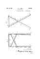
- Fig. l is a front view of a stand constructed in accordance with my invention.
- Fig. 2 is a side view of the stand
- Fig. 3 is a top plan view
- Fig. 4 is a fragmentary section taken substantially on the line 4 4 of Fig. 3;
- Fig. 5 is a side view of the stand folded
- Fig. 6 is a fragmentary section taken substantially on line 6--6 of Fig. 5;
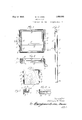
- Fig. 7 is a plan view of a tabletop applied to the stand.
- Fig. 8 isa fragmentary section, taken substantially on line 8-8 of Fig. 7.
- the stand comprises a rectangular top frame l, which is formed of a suitable length of iron of angular cross-section, the iron employed being of T-shape in cross-section, as in Fig. 4.
- r rFhistop frame is mounted upon suitable legs or supports YWhich are 4disposed in pairs atopposite sides of the frame, each pair ⁇ comprising an inner support 2 and ank outer support 3.
- These supports are formed of angle iron Vand are oppositely directed, the inner support 2 opening inwardly toward the frame l.
- the supports 2 and 3 are pivotally secured together, intermediate their ends, at 4 and, when the table is set up,are disposed in crossed relation.
- the outer supports 3 are connected by crossed braces 5, riveted or otherwise suitably secured thereto, these braces being secured together attheir intersection.
- the inner vsupports 2 are simi- Y larly connected by crossed braces 6.
- the suppo-rts 2 are pivotally secured at their upper ends, at 7, to top frame l and the supports 3 are detachably secured at their upper ends to the top frame by means of screws 8 which pass through the supports 3 and thread into the top frame, or in any other suitable manner.
- a The outer flange of support 3y is set at an angle to provide an element 3a, forming a foo-t which bears upon the supporting surface, the inner flange of support 2 being similarly bent at its lower end to provide a foot element 2a?.
- the elements 2EL and 3a are preferably provided With suitableopenings for reception of securing members for fastening the supports to the-floor or supporting surface.
- a stand constructed in the manner illustrated and described occupies but little space and, due to the angle construction of the supporting members 2 and 3 and the cross-sectional shape of the frame l, is capable of sustaining heavy loads.
- Horizontal flange la of the frame projects inwardly thereof andy provides a seat for a base plate or member of a vending machine, typewriting machine, or other object which it is desired to support upon the stand.
- I preferably provide channel strips 9 which are secured to flange 1a, in inverted position upon the upper face thereof, by means of screws 10 passing through the strip and through the flange, the screw 10 receiving a nut 11 which bears against the under face of flange 1a. Any other suitable or preferred means can be provided for holding the strips 9 in position.
- top frame-'1 can bemade to accommodate the base plate or member of thefparticular machine to be supported by the stand, so long as such base member is of greater extent than the opening defined by flange 1a.
- I also preferably provide a flat bar'12 which is riveted or otherwise suitably secured to the under face of flange 1a.
- This bar is'provided with an opening 13 for reception of a bolt-or other suitable securing element, which may also pass through the base member of the machine or object mounted upon the stand. This provides simple and efficient means whereby the machine upon the stand may be effectively secured theretoin such manner asV to prevent its unauthorized removal.
- the stand When the stand is not in use, it may be readily folded so as to occupy but small space.
- the screws 8 are removed, after which the top frame 1 is swung downwardly so as to fit snugly between the supporting menibers 2.
- the width or vertical height of the' top frame 1 corresponds to the width of the outer flanges of the inner supporting members 2- so that the top frame is disposed within such members, after which the outer supporting members 3 are swung about the pivots l into superposed parallelv relation toV the inner members 2, thus completing the folding of the stand.
- the top frameV 1 is confined between the inner flanges of the supporting members 2 and the crossed braces 5 of the outer supporting members 3, and is disposed in parallelism with the supporting members. rifhe supporting members thus cooperate to house and confine the top frame and the stand, as a whole, occupies but very little space and may be readily stacked when folded.
- I have illustrated my stand as used for a table.
- I provide a table top 13, which may be formed of wood or any other suitable material and is of a size to fit within the outer 'flange 1b ofI framel 1 and seat upon theinner flange 1'a thereof.
- This top 13 is provided with-aV suitable number of clips 111 pivotally secured to the under face thereof, as by means of screws 15, these clips being adapted anddisposed toengage'beneatn' flange 1 when turned about the screws 15 into operative position. In this manner, the top 13 can be readily secured in position in the frame 1 and, when desired, can be readily removed therefrom.
- a stand constructed in accordance with my invention may be used for many other purposes than thoseabove enumerated, and this sta-nd is particularly adapted for supporting unusually heavy loads, such as could not be satisfactorily supported by standsc'onstructed ofwood or of metal other than of. angle cross-section and not of excessive thickness.
- I-'claimzl 1.
- a folding stand a rectangular top frame, pairs ofv supporting members ypivoted together in crossed relation at opposite sides of the frame, each pair comprising an inner member and an outer member, said inner member being of heroes-sectionl and having an outer flange pivoted to thetopv frame andan inner flange projecting inwardly toward,-
- top frame - means for releasably securingthe outer members to the frame', and cross-- braces connecting said outer members/the top frame whenA releasedv fitting intothel inner supporting members and the cross-braces confining saidA frame4 in said inner members when the'supporting members of each. pair are disposed in superposed parallel relation.
- a rectangular top frame formed in cross-section to provide an outer vertical flange and an inwardly pro'- jecting horizontal flange, pairs ofsupporting members of L cross-section pivoted together in crossed relation atopposit-e sides of the frame, the members of eachpair being oppositely disposed with the inner member opening upwardly and inwardly' toward the frame, the outer flanges of the innermembers being pivoted at their upper ends to the frame, means releasablyl securing the inner flanges-of Vthe outer members to the frame, said frame when released swinging downwardly into the inner supporting members, and means carried' by the outer supporting member's'for confining the'frame in said inner members whenfthe' members of each-pair l are disposed in superpo'sed parallel relation.
Landscapes
- Assembled Shelves (AREA)
Description
May 10, 1932. w. w. HORN FOLDING STAND Filed April so, 1928 2 Sheets-Sheet W. W. HORN FOLDING STAND May 10. 1932.
Filed April 50, 1928 2 Sheets-Sheet 2 Patented May 10, 1932 vUNITED STATES PATENT carica WILLIAM W. HORN, OF RIVER FOREST, ILLINOIS FOLDING STAND Application alec April 3o,
This invention relates to supporting devices, and more particularly to a folding stand or similar structure.
There is a demand for stands and similar structures for use in oflices and other establishments which, when not in use, are capable of being vstowed in a small space, such stands being used forsupporting typewriting machines, calculating machines, and oth- 10, er machines of appreciable weight relative to their size. It has been difcult to devise suitable folding stands capable of satisfactorily supporting typewriting machines, for instance, due to the weight of such a machine and the conditions of use thereof.
The primary object of my invention is to provide a folding stand, which, when in use, is capable of supporting typewriting machines and various other objects in a satisfactory manner. This stand is also well adapted for supporting dispensing machines, such `as coin-operated machines, which machines are frequently quite heavy relative to their size.
A further object of my invention is to provide a stand of this character which may be produced at small cost and which is capable of supporting a heavy load.
Another object of my invention is to provide a stand which can be readily adapted to receive any one of several sizes of base plates or members associated with the machine to be supported by the stand. l
A still further Objectis to provide a stand of this character which caribe readily folded, so as to occupy but little space; this stand having associated therewith. brace members which coact with the supporting members or legs of the stand to confinefthe top frame when the stand is folded.
Further objects and advantages of my invention will appear from the detailed description.
In the drawings: j Y
Fig. l is a front view of a stand constructed in accordance with my invention;
Fig. 2 is a side view of the stand;
Fig. 3 is a top plan view; i l
Fig. 4 is a fragmentary section taken substantially on the line 4 4 of Fig. 3;
1928. Serial No. 273,790.
Fig. 5 is a side view of the stand folded;
Fig. 6 is a fragmentary section taken substantially on line 6--6 of Fig. 5;
Fig. 7 is a plan view of a tabletop applied to the stand; and
Fig. 8 isa fragmentary section, taken substantially on line 8-8 of Fig. 7.
The stand comprises a rectangular top frame l, which is formed of a suitable length of iron of angular cross-section, the iron employed being of T-shape in cross-section, as in Fig. 4.r rFhistop frame is mounted upon suitable legs or supports YWhich are 4disposed in pairs atopposite sides of the frame, each pair` comprising an inner support 2 and ank outer support 3. These supports are formed of angle iron Vand are oppositely directed, the inner support 2 opening inwardly toward the frame l. The supports 2 and 3 are pivotally secured together, intermediate their ends, at 4 and, when the table is set up,are disposed in crossed relation. The outer supports 3 are connected by crossed braces 5, riveted or otherwise suitably secured thereto, these braces being secured together attheir intersection. The inner vsupports 2 are simi- Y larly connected by crossed braces 6.
The suppo-rts 2 are pivotally secured at their upper ends, at 7, to top frame l and the supports 3 are detachably secured at their upper ends to the top frame by means of screws 8 which pass through the supports 3 and thread into the top frame, or in any other suitable manner. A The outer flange of support 3y is set at an angle to provide an element 3a, forming a foo-t which bears upon the supporting surface, the inner flange of support 2 being similarly bent at its lower end to provide a foot element 2a?. The elements 2EL and 3a are preferably provided With suitableopenings for reception of securing members for fastening the supports to the-floor or supporting surface.
A stand constructed in the manner illustrated and described occupies but little space and, due to the angle construction of the supporting members 2 and 3 and the cross-sectional shape of the frame l, is capable of sustaining heavy loads. Horizontal flange la of the frame projects inwardly thereof andy provides a seat for a base plate or member of a vending machine, typewriting machine, or other object which it is desired to support upon the stand. I preferably provide channel strips 9 which are secured to flange 1a, in inverted position upon the upper face thereof, by means of screws 10 passing through the strip and through the flange, the screw 10 receiving a nut 11 which bears against the under face of flange 1a. Any other suitable or preferred means can be provided for holding the strips 9 in position. These stripsprovide fillers and, by employing strips of different widths, top frame-'1 can bemade to accommodate the base plate or member of thefparticular machine to be supported by the stand, so long as such base member is of greater extent than the opening defined by flange 1a.
Ialso preferably provide a flat bar'12 which is riveted or otherwise suitably secured to the under face of flange 1a. This bar is'provided with an opening 13 for reception of a bolt-or other suitable securing element, which may also pass through the base member of the machine or object mounted upon the stand. This provides simple and efficient means whereby the machine upon the stand may be effectively secured theretoin such manner asV to prevent its unauthorized removal.
When the stand is not in use, it may be readily folded so as to occupy but small space. For this purpose, the screws 8 are removed, after which the top frame 1 is swung downwardly so as to fit snugly between the supporting menibers 2. The width or vertical height of the' top frame 1 corresponds to the width of the outer flanges of the inner supporting members 2- so that the top frame is disposed within such members, after which the outer supporting members 3 are swung about the pivots l into superposed parallelv relation toV the inner members 2, thus completing the folding of the stand. With the parts in' the position referred to and ill'ustrated in Fig. 5, the top frameV 1 is confined between the inner flanges of the supporting members 2 and the crossed braces 5 of the outer supporting members 3, and is disposed in parallelism with the supporting members. rifhe supporting members thus cooperate to house and confine the top frame and the stand, as a whole, occupies but very little space and may be readily stacked when folded.
,In Figs. 7 and 8, I have illustrated my stand as used for a table. F or this purpose, I provide a table top 13, which may be formed of wood or any other suitable material and is of a size to fit within the outer 'flange 1b ofI framel 1 and seat upon theinner flange 1'a thereof. This top 13 is provided with-aV suitable number of clips 111 pivotally secured to the under face thereof, as by means of screws 15, these clips being adapted anddisposed toengage'beneatn' flange 1 when turned about the screws 15 into operative position. In this manner, the top 13 can be readily secured in position in the frame 1 and, when desired, can be readily removed therefrom. Obviously, a stand constructed in accordance with my invention may be used for many other purposes than thoseabove enumerated, and this sta-nd is particularly adapted for supporting unusually heavy loads, such as could not be satisfactorily supported by standsc'onstructed ofwood or of metal other than of. angle cross-section and not of excessive thickness.
I-'claimzl 1. In a folding stand, a rectangular top frame, pairs ofv supporting members ypivoted together in crossed relation at opposite sides of the frame, each pair comprising an inner member and an outer member, said inner member being of heroes-sectionl and having an outer flange pivoted to thetopv frame andan inner flange projecting inwardly toward,-
the top frame,- means for releasably securingthe outer members to the frame', and cross-- braces connecting said outer members/the top frame whenA releasedv fitting intothel inner supporting members and the cross-braces confining saidA frame4 in said inner members when the'supporting members of each. pair are disposed in superposed parallel relation.
2. In a folding stand, al rectangular top frame, pai-rs of supportingymembers of L cross-section pivoted together in crossed: relation at opposite sidesfofv the frame, the members of each pair being oppositely disposed with the inner Vmember opening upwardly and inwardly toward the frame, the outer' flanges of the inner members being pivoted at their upper ends to the frame, mea-ns releasably securing theinner flanges of the outer members to the frame, said frame when released swinging downwardly into the inner supporting members, and means' carried by the outer supporting members for con-fining the frame iny said! inner members when the mem-bersof eachA pair are disposed' in superposedl parallel relation.
3. In a fol-ding stand, a rectangular top frame formed in cross-section to provide an outer vertical flange and an inwardly pro'- jecting horizontal flange, pairs ofsupporting members of L cross-section pivoted together in crossed relation atopposit-e sides of the frame, the members of eachpair being oppositely disposed with the inner member opening upwardly and inwardly' toward the frame, the outer flanges of the innermembers being pivoted at their upper ends to the frame, means releasablyl securing the inner flanges-of Vthe outer members to the frame, said frame when released swinging downwardly into the inner supporting members, and means carried' by the outer supporting member's'for confining the'frame in said inner members whenfthe' members of each-pair l are disposed in superpo'sed parallel relation.
4. In a stand, a top :frame of angle crosssection and having a vertical flange and a horizontal flange of the T-shape directed inwardly of the frame, a top fitting into the frame and seating upon the horizontal ange thereof, and clips mounted on the under face of the top and engaging beneath said horizontal flange.
In Witness whereof, I hereunto subscribe my name this 26th day of April, 1928.
WILLIAM W. HORN.
Priority Applications (1)
| Application Number | Priority Date | Filing Date | Title |
|---|---|---|---|
| US273790A US1858085A (en) | 1928-04-30 | 1928-04-30 | Folding stand |
Applications Claiming Priority (1)
| Application Number | Priority Date | Filing Date | Title |
|---|---|---|---|
| US273790A US1858085A (en) | 1928-04-30 | 1928-04-30 | Folding stand |
Publications (1)
| Publication Number | Publication Date |
|---|---|
| US1858085A true US1858085A (en) | 1932-05-10 |
Family
ID=23045407
Family Applications (1)
| Application Number | Title | Priority Date | Filing Date |
|---|---|---|---|
| US273790A Expired - Lifetime US1858085A (en) | 1928-04-30 | 1928-04-30 | Folding stand |
Country Status (1)
| Country | Link |
|---|---|
| US (1) | US1858085A (en) |
-
1928
- 1928-04-30 US US273790A patent/US1858085A/en not_active Expired - Lifetime
Similar Documents
| Publication | Publication Date | Title |
|---|---|---|
| US2722971A (en) | Picnic table and the like | |
| US2624469A (en) | Foldable vertically adjustable table | |
| US2481935A (en) | Combined bench and table | |
| US2245825A (en) | Folding stand | |
| US2791477A (en) | Foldable table with hinged top | |
| US3057670A (en) | Collapsible utility table and seat for boats | |
| US2702585A (en) | Table and bench structure | |
| US2118676A (en) | Lawn chair | |
| US1890129A (en) | Convertible seat and table | |
| US2581883A (en) | Baby bathing stand | |
| US1553821A (en) | Wall furniture | |
| US1858085A (en) | Folding stand | |
| US1636608A (en) | Sales rack | |
| US2060000A (en) | Combination chair and ironing board | |
| US2553939A (en) | Article of furniture and hoisting and transporting device therefor | |
| US1941838A (en) | Display device | |
| US2572585A (en) | Folding desk and table | |
| US2367011A (en) | Combined table and benches | |
| US2175734A (en) | Folding ironing board | |
| US1997742A (en) | Combined workbench and rack | |
| US1184886A (en) | Revolving-top leg-detachable stool. | |
| US1956265A (en) | Convertible laundering and kitchen table | |
| US3006108A (en) | Work bench | |
| US1646939A (en) | Combined table and seat structure | |
| DE450069C (en) | Device on water basin with foldable support plate for vessels to be filled |