US1858068A - Time card holder - Google Patents
Time card holder Download PDFInfo
- Publication number
- US1858068A US1858068A US487511A US48751130A US1858068A US 1858068 A US1858068 A US 1858068A US 487511 A US487511 A US 487511A US 48751130 A US48751130 A US 48751130A US 1858068 A US1858068 A US 1858068A
- Authority
- US
- United States
- Prior art keywords
- casing
- card holder
- side bars
- members
- assembled
- Prior art date
- Legal status (The legal status is an assumption and is not a legal conclusion. Google has not performed a legal analysis and makes no representation as to the accuracy of the status listed.)
- Expired - Lifetime
Links
- 238000005192 partition Methods 0.000 description 30
- 238000006073 displacement reaction Methods 0.000 description 8
- 239000002184 metal Substances 0.000 description 6
- 210000005069 ears Anatomy 0.000 description 4
- 230000000717 retained effect Effects 0.000 description 2
- IJJWOSAXNHWBPR-HUBLWGQQSA-N 5-[(3as,4s,6ar)-2-oxo-1,3,3a,4,6,6a-hexahydrothieno[3,4-d]imidazol-4-yl]-n-(6-hydrazinyl-6-oxohexyl)pentanamide Chemical compound N1C(=O)N[C@@H]2[C@H](CCCCC(=O)NCCCCCC(=O)NN)SC[C@@H]21 IJJWOSAXNHWBPR-HUBLWGQQSA-N 0.000 description 1
- 241000713650 Falco subbuteo Species 0.000 description 1
- 238000010276 construction Methods 0.000 description 1
- 238000000034 method Methods 0.000 description 1
- 238000003825 pressing Methods 0.000 description 1
- 238000000926 separation method Methods 0.000 description 1
- 238000003466 welding Methods 0.000 description 1
Images
Classifications
-
- B—PERFORMING OPERATIONS; TRANSPORTING
- B42—BOOKBINDING; ALBUMS; FILES; SPECIAL PRINTED MATTER
- B42F—SHEETS TEMPORARILY ATTACHED TOGETHER; FILING APPLIANCES; FILE CARDS; INDEXING
- B42F17/00—Card-filing arrangements, e.g. card indexes or catalogues or filing cabinets
- B42F17/02—Card-filing arrangements, e.g. card indexes or catalogues or filing cabinets in which the cards are stored substantially at right angles to the bottom of their containers
- B42F17/08—Construction of the containers, e.g. trays or drawers
Definitions
- This invention relates to a casing or holder in which time cards or similar records may be conveniently kept.
- our invention relates to the provision of a card holder comprising an open front casing'7 a plurality of card separating partitions and improved devices for assembling and retaining the partition members in the enclosing casing.
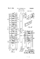
- FIG. 1 is a front elevation of our improved holder, cut away in parts
- Fig. 2 is a side elevation of the holder shown in Fig. 1;
- Fig. 3 is an end view. looking in the direction of the arrow 3 in Fig. 1, with the bottom end of the holder removed;
- Fig. 4 is a perspective view ofthe top end of the card holder
- Fig. 5 is a front view of certain parts and shows the method of assembling said parts
- Fig. 6 is a sectional end elevation of the casing
- Fig. 7 is a perspective view of a portion of one of the side bars
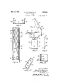
- Fig. 8 is a front view of one of the partition members
- Fig. 9 is a side elevation thereof
- Fig. 10 is an end view of the partition member, looking in the direction of the arrow 10 in Fig. 8;
- Fig. 11 is an enlarged partial sectional side elevation, taken along the line 11-11 in Fig. 1;
- Fig. 12 is a perspective view of the bottom end of the casing.
- Fig. 13 is a detail sectional View, taken along the line 13-13 in Fig. 2.
- our improved card holder as of sheet metal construction and comprising an open front casing 20, end members 21 and 22, right and left side bars 23 and 24 and partition members 25.
- the casing 2O is preferably formed from a single piece of sheet metal, bent up by a series of forming ⁇ operations to vthe cross section shown in Fig. 6.
- the casing 2O comprises a back and forwardly projecting ⁇ side portions 31.
- the middle portion of the bach is pressed or displaced forwardly to provide grooves 32 to receive the back edges of the side bars 23 and 24.
- the side portions 31 of the casing are bent in-Y wardly, as indicated at 33, and are flanged rearwardly as shown at 34, thus forming guideways for the front edges of the side ars.
- the side bars 23 and 24 are flanged at ,A
- Spaced notches or open ings 40 are formed in theinner front corners of the side bars 23 and 24 for a purpose to be described.
- the top end member 21 (Fig. 4) is formed in the shape of an open box-like structure, adapted to tit snugly over the upper end of the casing 20 and to be permanently secured thereto by spot welding or in any other convenient manner.
- the bottom end member 22 (Fig. 12) is similarly formed as a rectangular boxlilze structure adapted to lit over the lower end of the casing 20.
- the bottom member 22, Y is similarly formed as a rectangular boxlilze structure adapted to lit over the lower end of the casing 20.
- the end members 21 and 22 are each provided with an inturned flange 45 (Figs. 4 and 12) tting between the flanges 34 of the casing and form a continuation thereof, thus providing a pleasing ornamental finish.
- the separating members 25 are formed from pieces of flat thin sheet metal and are preferably ribbed, as indicated at 50 (Figs. 8 and 9) to provide increased stiffness. Each separating member is also provided with a rearwardly projecting ear 51 (Fig. 9) and a forwardly projecting vlower end flange 52. When the separating members 25 are assembled, as shown in Fig. 1l, the flanges 52 eX- tend forward and the ears 51 extend rearward and by their combined action they effectively close the bottom end Vof the pockets formed between adjacent separating members, making it impossible for a card to slip down between the members 25 to a position lower than was intended.
- each partition member 25 is displaced rearwardly and severed along its end edges to provide'a holder for a name or numeral card.
- Lugs 56 are displaced rearwardly to provide stops which will prevent longitudinal displacement of the inserted card.
- each partition member 25 is rolled tightly over a cross wire 57 having down-turned or offset ends 58. After these parts are assembled, they are preferably japanned or enameled and this finishing operation effectively prevents slipping of the cross wires 57 relative to the partition members 25.
- the ends 58 of the partition cross wires 57 are inserted through the openings 40 in the side bars 23 and 24, the ends 58 extending down behind or outside of the side bars, as indicated in Fig. 11, and effectively preventing lateral separation or spreading thereof.
- the side bars are inserted in the lower ends of the grooves or guideways formed at thesides of the casing 2O and are pushed upward therein.
- the partition members are assembled progressively, at the same time pushing the side bars gradually upward into the casing.
- a cover plate 60 is mounted by a cross wire in the lowest pair of openings 40 and forms a closure or front for the lower end of the card holder. After the parts are all thus assembled, the bottom end member 22 is placed on and secured to the lower end of the casing, thus preventing displacement of the side bars and holding all parts in assembled relation.
- the bottom end member 22 is provided with upwardly displaced ears 62 and 63 F igs. 1l and 12).
- the ear 62 when in assembled position, engages the front edge of the flange 52 at the lower end of the lowest partition member 25 and prevents forward displacenient thereof, while the lug or ear 63 engages the rear side of the cover plate G0 and prevents rearward displacement of the plate.
- Ears or brackets are provided on the ends 2l and 22 by which the card holder may be secured to a supporting wall.
- a card holder comprising an elongated open-front casing having in-turned front edge portions, a plurality of partition niembers, and side bars in which 'said partition members are mounted, said side bars being longitudinally slidable in said casing for assembly therewith.
- a card holder comprising an elongated open-front casing having iii-turned and rearwardly flanged front edge portions, a plurality of partition members, and side bars in which said partition members are mounted, said side bars being longitudinally slidable in said casing for assembly therewith and being retained therein by said rearwardly flanged front edge portions.
- a plurality of partition members each comprising a sheet metal body portion provided with a forwardly turned and outwardly projecting flange at its lower end and with a rearwardly projecting card-supporting ear struck from said body portion and vertically spaced from said flange, and means to hold said partition members in superposed assembled relation, with the out-turned flange of each partition member overlapping and cooperating with the card-supporting ear of the next lower partition member to effectively close the bottom of the pocket formed between each pair of adjacent partition members when assembled in said holding means.
- a card holder comprising a casing, a plurality of partition members, side bars for said members slidably mounted in said casing, an end for said casing, and means to detachab-ly secure said end in position to retain said side bars in said casing, said end having an inwardly projecting ear effective to position the lower end of the lowest partition member.
- a card holder comprising a casing, a plurality of partition members Jforming relatively deep pockets, side bars slidably mounted in said casing, and in which said partition members are detachably secured, and a detachable end for said casing ei'ective to retain said side bars in position, said end having inwardly displaced portions effective to engage shoulders on said casing and thereby prevent accidental displacement of said end.
- a card holder comprising a sheet metal body portion forming a back and sides of a casing, a top end permanently secured to said casing, a plurality of partition members, side bars in which said members are assembled, said bars being slidable endwise in said casing, and a bottom end for said casing detachablyv secured thereto and holding said side bars from endwise displacement in said casing.
- a card holder comprising a casing, a plurality of partition members, and side bars in which said members are assembled, said side bars being slidable endwise in said casing, and the front edges of said casing being in-turned and rearwardly flanged and the middle portion of the back of said casing being displaced forwardly, whereby runways for said side bars are provided.
Landscapes
- Sheet Holders (AREA)
Description
MFM 10, 1932- E.. G. wATKlNs ET Al. 1,858,068
TIME CARD HQLDER Filed Oct. 9, 1930 2 Sheets-Seeb l May 10, 1932 E. G. wATKlNs ET Al. 1,858,068
T IME CARD HOLDER Filed OGt..A 9, 1930 2 Sheets-Sheet 2 Patented May 10, 1932 UNITED STATES PATENT OFFICEg EDWARD G. WATKINS AND HAROLD E. HOBBY, OF GARDNER, MASSACHUSETTS, AS-
SIGNORS TO SIMPLEX TIME RECORDER COMPANY, OF GARDNER, MASSACHUSETTS,
A CORPORATION F MASSACHUSETTS TIME CARD HOLDER Application filed October 9, 1930. Serial No. 487,511.
This invention relates to a casing or holder in which time cards or similar records may be conveniently kept.
It is the general object of our invention to provide a card holder so designed that it may be easily and economically constructed and that it will be well adapted to the purposes intended.
More specifically our invention relates to the provision of a card holder comprising an open front casing'7 a plurality of card separating partitions and improved devices for assembling and retaining the partition members in the enclosing casing.
Our invention further relates to arrangements and combinations of parts which will be hereinafter described and more particularly pointed out in the appended claims.
A preferred form of the invention is shown in the drawings, in which Fig. 1 is a front elevation of our improved holder, cut away in parts;
Fig. 2 is a side elevation of the holder shown in Fig. 1;
Fig. 3 is an end view. looking in the direction of the arrow 3 in Fig. 1, with the bottom end of the holder removed;
Fig. 4 is a perspective view ofthe top end of the card holder;
Fig. 5 is a front view of certain parts and shows the method of assembling said parts;
Fig. 6 is a sectional end elevation of the casing;
Fig. 7 is a perspective view of a portion of one of the side bars;
Fig. 8 is a front view of one of the partition members;
Fig. 9 is a side elevation thereof;
Fig. 10 is an end view of the partition member, looking in the direction of the arrow 10 in Fig. 8;
Fig. 11 is an enlarged partial sectional side elevation, taken along the line 11-11 in Fig. 1;
Fig. 12 is a perspective view of the bottom end of the casing; and
Fig. 13 is a detail sectional View, taken along the line 13-13 in Fig. 2.
Referring to the drawings, we have shown our improved card holder as of sheet metal construction and comprising an open front casing 20, end members 21 and 22, right and left side bars 23 and 24 and partition members 25.
The casing 2O is preferably formed from a single piece of sheet metal, bent up by a series of forming` operations to vthe cross section shown in Fig. 6. The casing 2O comprises a back and forwardly projecting `side portions 31. The middle portion of the bach is pressed or displaced forwardly to provide grooves 32 to receive the back edges of the side bars 23 and 24. At their front edges, the side portions 31 of the casing are bent in-Y wardly, as indicated at 33, and are flanged rearwardly as shown at 34, thus forming guideways for the front edges of the side ars.
The side bars 23 and 24 are flanged at ,A
their front and back edges, as indicated at 36 and 37 in Fig. 7. Spaced notches or open ings 40 are formed in theinner front corners of the side bars 23 and 24 for a purpose to be described.
The top end member 21 (Fig. 4) is formed in the shape of an open box-like structure, adapted to tit snugly over the upper end of the casing 20 and to be permanently secured thereto by spot welding or in any other convenient manner.
The bottom end member 22 (Fig. 12) is similarly formed as a rectangular boxlilze structure adapted to lit over the lower end of the casing 20. The bottom member 22, Y
however, is designed for detachment and removal from the casing lwhen desired, and for this purpose is provided with inwardly projecting lugs or ears 42 (Fig. 13) adapted to cooperate with shoulders 43 formed ,by pressing inward portions 44 of the sides 31. When the bottom end 22 is forced over the lower end of the casing, the parts 42 and 43 cooperate to firmly retain the same in place but they may be separated by inserting Vthe edge of a tool when it is desired to remov the bottom of the casing. Y
The end members 21 and 22 are each provided with an inturned flange 45 (Figs. 4 and 12) tting between the flanges 34 of the casing and form a continuation thereof, thus providing a pleasing ornamental finish.
The separating members 25 are formed from pieces of flat thin sheet metal and are preferably ribbed, as indicated at 50 (Figs. 8 and 9) to provide increased stiffness. Each separating member is also provided with a rearwardly projecting ear 51 (Fig. 9) and a forwardly projecting vlower end flange 52. When the separating members 25 are assembled, as shown in Fig. 1l, the flanges 52 eX- tend forward and the ears 51 extend rearward and by their combined action they effectively close the bottom end Vof the pockets formed between adjacent separating members, making it impossible for a card to slip down between the members 25 to a position lower than was intended.
A portion 54 of each partition member 25 is displaced rearwardly and severed along its end edges to provide'a holder for a name or numeral card. Lugs 56 are displaced rearwardly to provide stops which will prevent longitudinal displacement of the inserted card.
The upper end of each partition member 25 is rolled tightly over a cross wire 57 having down-turned or offset ends 58. After these parts are assembled, they are preferably japanned or enameled and this finishing operation effectively prevents slipping of the cross wires 57 relative to the partition members 25.
In assembling my improved card holder, the ends 58 of the partition cross wires 57 are inserted through the openings 40 in the side bars 23 and 24, the ends 58 extending down behind or outside of the side bars, as indicated in Fig. 11, and effectively preventing lateral separation or spreading thereof.
After the partition members are thus assembled with the side bars, the side bars are inserted in the lower ends of the grooves or guideways formed at thesides of the casing 2O and are pushed upward therein. Preferably the partition members are assembled progressively, at the same time pushing the side bars gradually upward into the casing.
A cover plate 60 is mounted by a cross wire in the lowest pair of openings 40 and forms a closure or front for the lower end of the card holder. After the parts are all thus assembled, the bottom end member 22 is placed on and secured to the lower end of the casing, thus preventing displacement of the side bars and holding all parts in assembled relation.
The bottom end member 22 is provided with upwardly displaced ears 62 and 63 F igs. 1l and 12). The ear 62, when in assembled position, engages the front edge of the flange 52 at the lower end of the lowest partition member 25 and prevents forward displacenient thereof, while the lug or ear 63 engages the rear side of the cover plate G0 and prevents rearward displacement of the plate.
Ears or brackets are provided on the ends 2l and 22 by which the card holder may be secured to a supporting wall.
Having thus described our improved card holder, it will be evident that all parts thereof may be easily and economically made from sheet metal and that they may be made up in large quantities of interchangeable parts, which may be assembled as desired. Furthermore, the assembling operation is exceedingly simple and when the parts are assembled, displacement thereof is practically impossible unless the bottoni end members 22 are intentionally removed.
Having thus described our invention and the advantages thereof, we do not wish to be limited to the details herein disclosed, other- Wise than as set forth in the claims, but what we claim is l. A card holder comprising an elongated open-front casing having in-turned front edge portions, a plurality of partition niembers, and side bars in which 'said partition members are mounted, said side bars being longitudinally slidable in said casing for assembly therewith.
2. A card holder comprising an elongated open-front casing having iii-turned and rearwardly flanged front edge portions, a plurality of partition members, and side bars in which said partition members are mounted, said side bars being longitudinally slidable in said casing for assembly therewith and being retained therein by said rearwardly flanged front edge portions.
3. rl`he combination in a card holder as set forth in claim 2, in which the side bars are provided with out-turned front and rear flanged portions, and are also provided with spaced openings adjacent their front inner corners to receive the ends of outwardly projecting portions of said partition members.
4. The combination in a card holder as set forth in claim 2, in which the side bars are provided with spaced openings, and in which the partition members are provided with cross wires, the ends of said cross wires being received in said openings and being held from displacement therefrom by the rearwardly flanged front edge portions of the casing when the parts of the card holder are assembled. Y
5. The combination in a card holder as set forth in claim 2, in which the side bars are provided with spaced openings, and in which the partition members are provided with cross wires having offset ends which extend through the openings in the side bars, said cross wires being retained from displacement therefrom by the rearwardly flanged front edge portions ofthe casing when theparts of the card holder are assembled, and said offset ends being positioned outside of said side bars and out of alignment with said openings and preventing spreading of said casing.
6. In a card holder, a plurality of partition members each comprising a sheet metal body portion provided with a forwardly turned and outwardly projecting flange at its lower end and with a rearwardly projecting card-supporting ear struck from said body portion and vertically spaced from said flange, and means to hold said partition members in superposed assembled relation, with the out-turned flange of each partition member overlapping and cooperating with the card-supporting ear of the next lower partition member to effectively close the bottom of the pocket formed between each pair of adjacent partition members when assembled in said holding means.
7. A card holder comprising a casing, a plurality of partition members, side bars for said members slidably mounted in said casing, an end for said casing, and means to detachab-ly secure said end in position to retain said side bars in said casing, said end having an inwardly projecting ear effective to position the lower end of the lowest partition member.
8. A card holder comprising a casing, a plurality of partition members Jforming relatively deep pockets, side bars slidably mounted in said casing, and in which said partition members are detachably secured, and a detachable end for said casing ei'ective to retain said side bars in position, said end having inwardly displaced portions effective to engage shoulders on said casing and thereby prevent accidental displacement of said end.
9. A card holder comprising a sheet metal body portion forming a back and sides of a casing, a top end permanently secured to said casing, a plurality of partition members, side bars in which said members are assembled, said bars being slidable endwise in said casing, and a bottom end for said casing detachablyv secured thereto and holding said side bars from endwise displacement in said casing.
10. The combination in a card holder as set forth in claim 9 in which the ends are provided with brackets fixed thereto and attachable to a supporting struct-ure.
11. A card holder comprising a casing, a plurality of partition members, and side bars in which said members are assembled, said side bars being slidable endwise in said casing, and the front edges of said casing being in-turned and rearwardly flanged and the middle portion of the back of said casing being displaced forwardly, whereby runways for said side bars are provided.
In testimony whereof we have hereunto affixed our signatures.
EDWARD G. WATKINS. HAROLD E. HOBBY.
Priority Applications (1)
| Application Number | Priority Date | Filing Date | Title |
|---|---|---|---|
| US487511A US1858068A (en) | 1930-10-09 | 1930-10-09 | Time card holder |
Applications Claiming Priority (1)
| Application Number | Priority Date | Filing Date | Title |
|---|---|---|---|
| US487511A US1858068A (en) | 1930-10-09 | 1930-10-09 | Time card holder |
Publications (1)
| Publication Number | Publication Date |
|---|---|
| US1858068A true US1858068A (en) | 1932-05-10 |
Family
ID=23936025
Family Applications (1)
| Application Number | Title | Priority Date | Filing Date |
|---|---|---|---|
| US487511A Expired - Lifetime US1858068A (en) | 1930-10-09 | 1930-10-09 | Time card holder |
Country Status (1)
| Country | Link |
|---|---|
| US (1) | US1858068A (en) |
Cited By (3)
| Publication number | Priority date | Publication date | Assignee | Title |
|---|---|---|---|---|
| US3691664A (en) * | 1971-04-26 | 1972-09-19 | Alexander Stoian | Adjustable card holder |
| US4938367A (en) * | 1989-05-12 | 1990-07-03 | Krapf Business Systems, Inc. | Weldment-free document holder |
| US10010197B1 (en) * | 2017-05-26 | 2018-07-03 | W.A. Krapf, Inc. | Document holding apparatus |
-
1930
- 1930-10-09 US US487511A patent/US1858068A/en not_active Expired - Lifetime
Cited By (3)
| Publication number | Priority date | Publication date | Assignee | Title |
|---|---|---|---|---|
| US3691664A (en) * | 1971-04-26 | 1972-09-19 | Alexander Stoian | Adjustable card holder |
| US4938367A (en) * | 1989-05-12 | 1990-07-03 | Krapf Business Systems, Inc. | Weldment-free document holder |
| US10010197B1 (en) * | 2017-05-26 | 2018-07-03 | W.A. Krapf, Inc. | Document holding apparatus |
Similar Documents
| Publication | Publication Date | Title |
|---|---|---|
| US1823285A (en) | Drawer construction | |
| US1890143A (en) | Desk tray | |
| US1735375A (en) | Filing cabinet | |
| US1656868A (en) | Metallic shelving | |
| US2105594A (en) | Card and pamphlet holder | |
| US1858068A (en) | Time card holder | |
| US2539963A (en) | Drawer containing cabinet | |
| US2176913A (en) | Storage cabinet | |
| US3120413A (en) | Multiple drawer box | |
| US1945773A (en) | Drawer partition | |
| US1333263A (en) | Drawer construction | |
| US1481561A (en) | Filing unit | |
| US2668746A (en) | Filing cabinet and drawer for microscope slides | |
| US1650663A (en) | Filing cabinet | |
| US1156812A (en) | Reference device for desks and the like. | |
| US2748513A (en) | Label holder for filing cabinet drawers | |
| US2051679A (en) | Display fixture | |
| US1521951A (en) | Holder | |
| US1754492A (en) | Filing-cabinet drawer | |
| US1837019A (en) | Index or file | |
| US1658394A (en) | Index device | |
| US1908185A (en) | Service device for toothpicks and the like | |
| US1719505A (en) | Display device | |
| US1972365A (en) | Coin holder | |
| US1200517A (en) | Filing drawer or receptacle. |