US1858055A - Fountain washing device - Google Patents
Fountain washing device Download PDFInfo
- Publication number
- US1858055A US1858055A US370226A US37022629A US1858055A US 1858055 A US1858055 A US 1858055A US 370226 A US370226 A US 370226A US 37022629 A US37022629 A US 37022629A US 1858055 A US1858055 A US 1858055A
- Authority
- US
- United States
- Prior art keywords
- nozzle
- water
- inlet
- outlet
- receptacle
- Prior art date
- Legal status (The legal status is an assumption and is not a legal conclusion. Google has not performed a legal analysis and makes no representation as to the accuracy of the status listed.)
- Expired - Lifetime
Links
- 238000005406 washing Methods 0.000 title description 8
- XLYOFNOQVPJJNP-UHFFFAOYSA-N water Substances O XLYOFNOQVPJJNP-UHFFFAOYSA-N 0.000 description 45
- 239000000344 soap Substances 0.000 description 25
- 230000008878 coupling Effects 0.000 description 6
- 238000010168 coupling process Methods 0.000 description 6
- 238000005859 coupling reaction Methods 0.000 description 6
- 230000001276 controlling effect Effects 0.000 description 5
- 235000019169 all-trans-retinol Nutrition 0.000 description 2
- 238000005266 casting Methods 0.000 description 2
- 238000005192 partition Methods 0.000 description 2
- 241001351439 Oneida Species 0.000 description 1
- 238000010276 construction Methods 0.000 description 1
- 230000000875 corresponding effect Effects 0.000 description 1
- 238000004851 dishwashing Methods 0.000 description 1
- 239000007788 liquid Substances 0.000 description 1
- 238000012856 packing Methods 0.000 description 1
- 230000000630 rising effect Effects 0.000 description 1
Images
Classifications
-
- A—HUMAN NECESSITIES
- A47—FURNITURE; DOMESTIC ARTICLES OR APPLIANCES; COFFEE MILLS; SPICE MILLS; SUCTION CLEANERS IN GENERAL
- A47L—DOMESTIC WASHING OR CLEANING; SUCTION CLEANERS IN GENERAL
- A47L17/00—Apparatus or implements used in manual washing or cleaning of crockery, table-ware, cooking-ware or the like
-
- Y—GENERAL TAGGING OF NEW TECHNOLOGICAL DEVELOPMENTS; GENERAL TAGGING OF CROSS-SECTIONAL TECHNOLOGIES SPANNING OVER SEVERAL SECTIONS OF THE IPC; TECHNICAL SUBJECTS COVERED BY FORMER USPC CROSS-REFERENCE ART COLLECTIONS [XRACs] AND DIGESTS
- Y10—TECHNICAL SUBJECTS COVERED BY FORMER USPC
- Y10T—TECHNICAL SUBJECTS COVERED BY FORMER US CLASSIFICATION
- Y10T137/00—Fluid handling
- Y10T137/8593—Systems
- Y10T137/86493—Multi-way valve unit
- Y10T137/86863—Rotary valve unit
-
- Y—GENERAL TAGGING OF NEW TECHNOLOGICAL DEVELOPMENTS; GENERAL TAGGING OF CROSS-SECTIONAL TECHNOLOGIES SPANNING OVER SEVERAL SECTIONS OF THE IPC; TECHNICAL SUBJECTS COVERED BY FORMER USPC CROSS-REFERENCE ART COLLECTIONS [XRACs] AND DIGESTS
- Y10—TECHNICAL SUBJECTS COVERED BY FORMER USPC
- Y10T—TECHNICAL SUBJECTS COVERED BY FORMER US CLASSIFICATION
- Y10T137/00—Fluid handling
- Y10T137/8593—Systems
- Y10T137/8807—Articulated or swinging flow conduit
- Y10T137/88078—Actuates valve
- Y10T137/88102—Rotary valve
Definitions
- My invention has for its object a fountain washing device in connection with combined hot and cold water faucets having a joint pivotally connected or swinging nozzle, pal'- ticularly a device for washing dishes and sup-v plying at will either hot or cold water to the nozzleor hot or cold water or soapy water or water with any other cleanser therein to a brush or any other desirable device attachable to the outlet ofthe soap receptacle and hasfor its objecta particularly simple. compact and unitary water dispensing device which can be readily applied in place of ordinary sink faucets, and which is controlled by the swinging nozzle.
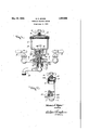
- Figure 1 is a front elevation, partly in section, of a fountain washing device embodying my invention.
- FIG. 2 is a side elevation thereof, partly in section and parts being broken away.
- My device comprises, generally, combined hotv and cold water faucets having a joint pivotally connected nozzle, a soap receptacle integral with said faucets having an inlet and an outlet for the water and a rotary Valve operable by the nozzle for controlling the flow of the Water to the nozzle or to the inlet or direct to the outlet of the receptacle.
- 1 represents the body or l main casting of my device having a conical opening 2 therein for the rotary valvey to be hereinafterdescribed.
- 3 and 4 are hollow branches extending from the main body 1 and are formed at their eXtreme ends with the hot and vcold water faucets 5 and 6, which are connected in theV usual manner to the hot and cold water supply.
- the body 1 is cored at the inner ends of the hollow branches 3 and 4 providing a wall or partition 7 .separating said branches from the conical opening 2.
- y 50 8 is the soap receptacle which is here shown 1929. Serial No. 870,226.
- the swinging nozzle here shown as integral with a hollow rotary valve 13 pivot- ⁇ 30 ally mounted and held in the conical opening or bore 2 of the body 1 by means of the shoulder 14 on the valve coacting with the top of an enlarged counterbore 15 at the lower end of the conical bore 2, and by means of the water tight joint consisting of a packing 16 anda nut 17 threading into the enlarged bore 15.
- the outlet 19 communicates with a. bore 20 entering the body l from the back thereof.
- a coupling 21 is threaded into the outer end of the bore 20 to which may be attached a fountain brush or mop or any desirable at- 7n tachment.
- the inlet passage 18 communicates with the conical bore 2 of the body 1.
- the rotary valve is hollow and is here shown -as provided with a partition 23 midway between its ends, thus providing it with upper and lower separated conduits 24 and 25.
- the lower conduit 25 is provided with ports 26 coacting with the ports 27 in the wall 7 for conducting the Water from the faucets 5 and 6 direct to the nozzle 12 and theupper 90 conduit 24 ⁇ is provided with inlet ports 28 for coasting with ports 29 in the wall 7 for conducting the water fromthe faucets to an outlet port 30 which coacts with the inlet passage 18 for the soap receptacle or with the 95 passage 22 communicating with the passage 20.
- the inlet passage 18 to the soap receptacle is provided with a ball or check valve 3l which prevents the soapy water therein from -10U ed valve 32 is provided in the cover 9 of the said receptacle. Opening of the valve brakes the vacuum created in the receptacle and allows the liquid therein to drain off vthrough the passage 19 and out through the coupling 21.
- the nozzle 12 When it is desired to pass the water from *the valves 5 and 6 through the 'soap receptacle, the nozzle 12 is turned to the left as shown in Figure 1, with the ports 26 and 27 out of alinement ⁇ and the ports'28 and 29 and the port 30 and passage 18 alined, permitting the Water to pass from the branches 3 and 4 to the' upper conduit of the lrotary valve, through the inlet passage 18 by the check valve 31 into the soap receptacle 8 where it mixes with thel cleanser therein and passes out through the outlet 19 tothe coupling 21.
- the nozzle When it-is desired to pass the clear water direct ato the coupling 21 without passing throu h the soap receptacle, the nozzle is turne one-half of a revolution to the ri ht from the position shown in Figure 1, t is movement of the nozzle again alines the ports 28 and 29 and disalines the port 30 with the inlet 4passage 18 and alines the said port 30 'with the' passage 22.
- a soap receptacle having an inlet and an outlet for the water and means operable by the nozzle for controlling the flow ofthe water to the nozzle, or to the inlet or outlet of said soap receptacle.
- a fountain washing device comprising combined hot and cold water faucets having a joint pivotally connected nozzle, a soap receptacle integral with said faucets having an inlet and an outlet forthe water, and means operable by the nozzle for controlling the flow of the water to the nozzle or to the inlet or outlet of the soap receptacle.
- 'A fountain washing device comprising combined hot and cold water faucets having a joint nozzle, a soap receptacle integral wit said faucets having an inlet and an outlet for the water and a valve operable to control the flow of the Water to the nozzle or to the inlet the nozzle, or to the inlet or outlet of the soap receptacle.
- a fountain washing device com rising combined hot and cold water faucets, aving a joint pivotally connected nozzle, a soap receptacle integral with said faucets having an inlet and an outlet for the water and means operable by the nozzle for controlling the flow of the Water to the nozzle, or to the inlet or outlet of said soap v'receptacle comprising a rotary valve having ports coacting with ports leading to the nozzle or to the inlet and outlet of the soap receptacle.
- a fountain washlng device includin V a laterally swingable nozzle, a valve contro ⁇ ling the flow of water to the nozzle, a soap receptacle having an inlet passage' and an zo outlet passage, and valve means operable by the lateral swinging of the nozzle foreontrolling the flow of water through the nozzle, to the inlet passage of the soap receptacle, and to the outlet passage o f the soap recep- 15 tacle respectively.
Landscapes
- Nozzles (AREA)
Description
May l0, 1932. H. c. MYERS l FOUNTAIN WASHING DEVICE Filed June 12, 1929 ATTORNEYS.
Patented y May 10, 1932 lUNITED STATES PATENT OFFICE HOWARD C. MYERS, OF ONEIDA, NEW YORK,.ASSIGNOR OF ONE-HALF T0 ISABEL If.
LEWIS, OF ONEIDA, NEW YORK FOUNTAIN WASHING DEVICE .Application filed June 12,
My invention has for its object a fountain washing device in connection with combined hot and cold water faucets having a joint pivotally connected or swinging nozzle, pal'- ticularly a device for washing dishes and sup-v plying at will either hot or cold water to the nozzleor hot or cold water or soapy water or water with any other cleanser therein to a brush or any other desirable device attachable to the outlet ofthe soap receptacle and hasfor its objecta particularly simple. compact and unitary water dispensing device which can be readily applied in place of ordinary sink faucets, and which is controlled by the swinging nozzle.
The invention consists in the novel features and in the combinations and constructions hereinafter set forth and claimed.
In describing this invention, reference is had to the accompanying drawings in which like characters designate correspon ding parts in all the views.
Figure 1 is a front elevation, partly in section, of a fountain washing device embodying my invention.
` Figure 2 is a side elevation thereof, partly in section and parts being broken away. e
My device comprises, generally, combined hotv and cold water faucets having a joint pivotally connected nozzle, a soap receptacle integral with said faucets having an inlet and an outlet for the water and a rotary Valve operable by the nozzle for controlling the flow of the Water to the nozzle or to the inlet or direct to the outlet of the receptacle.
1n the drawings, 1 represents the body or l main casting of my device having a conical opening 2 therein for the rotary valvey to be hereinafterdescribed. i
3 and 4 are hollow branches extending from the main body 1 and are formed at their eXtreme ends with the hot and vcold water faucets 5 and 6, which are connected in theV usual manner to the hot and cold water supply.
As here shown, the body 1 is cored at the inner ends of the hollow branches 3 and 4 providing a wall or partition 7 .separating said branches from the conical opening 2. y 50 8 is the soap receptacle which is here shown 1929. Serial No. 870,226.
as part of the main casting 1 and is located above the branches 3 and 4.
9 is a cover held tight in position by means of a wing screw 10 threading through a suitable yoke 11 against the top of the cover, the 55 yoke being detachably interlocked with the body of the soap receptacle, thereby providing an air tight receptacle.
12 is the swinging nozzle here shown as integral with a hollow rotary valve 13 pivot- `30 ally mounted and held in the conical opening or bore 2 of the body 1 by means of the shoulder 14 on the valve coacting with the top of an enlarged counterbore 15 at the lower end of the conical bore 2, and by means of the water tight joint consisting of a packing 16 anda nut 17 threading into the enlarged bore 15.
, 18 is the inlet for the water passing through to thev soap receptacle y8 and 19 is the outlet therefor.
The outlet 19 communicates with a. bore 20 entering the body l from the back thereof. A coupling 21 is threaded into the outer end of the bore 20 to which may be attached a fountain brush or mop or any desirable at- 7n tachment.
The inlet passage 18 communicates with the conical bore 2 of the body 1.
22 is a passage communicating with the `bore 2 and with the bore 20. This passage so 22 is a continuation of the passage 18.
As before stated, the rotary valve is hollow and is here shown -as provided with a partition 23 midway between its ends, thus providing it with upper and lower separated conduits 24 and 25.
The lower conduit 25 is provided with ports 26 coacting with the ports 27 in the wall 7 for conducting the Water from the faucets 5 and 6 direct to the nozzle 12 and theupper 90 conduit 24 `is provided with inlet ports 28 for coasting with ports 29 in the wall 7 for conducting the water fromthe faucets to an outlet port 30 which coacts with the inlet passage 18 for the soap receptacle or with the 95 passage 22 communicating with the passage 20. l
The inlet passage 18 to the soap receptacle is provided with a ball or check valve 3l which prevents the soapy water therein from -10U ed valve 32 is provided in the cover 9 of the said receptacle. Opening of the valve brakes the vacuum created in the receptacle and allows the liquid therein to drain off vthrough the passage 19 and out through the coupling 21.
In operation, when it is desired to use the faucets in the regular way with the water passing from'either hot or cold water faucet or both to the nozzle, the pivoted nozzle 12 is swung forwarder one-quarter turn is made to the right from the position shown in Figure 1.
This movement alims the ports 27 with the ports 26 and disalines the ports 28- and 29 'allowing the Water to pass to the lower conduit 25 of the rotary valve and thence to the nozzle 12 and closes the entrance to the upper conduit 24 of said rotary valve.
When it is desired to pass the water from *the valves 5 and 6 through the 'soap receptacle, the nozzle 12 is turned to the left as shown in Figure 1, with the ports 26 and 27 out of alinement `and the ports'28 and 29 and the port 30 and passage 18 alined, permitting the Water to pass from the branches 3 and 4 to the' upper conduit of the lrotary valve, through the inlet passage 18 by the check valve 31 into the soap receptacle 8 where it mixes with thel cleanser therein and passes out through the outlet 19 tothe coupling 21. I When it-is desired to pass the clear water direct ato the coupling 21 without passing throu h the soap receptacle, the nozzle is turne one-half of a revolution to the ri ht from the position shown in Figure 1, t is movement of the nozzle again alines the ports 28 and 29 and disalines the port 30 with the inlet 4passage 18 and alines the said port 30 'with the' passage 22.
In this position, the clear water will pass directfrom the upper conduit 24 of the rotary valve through the port 30, passage 22, bore 20 and coupling 21.
Obviously, when the nozzle is turned to the `left as shown in Figure 1, either hot or cold j water or both will pass through the soap receptacle and provide soapy water for any at ytachment used on the coupling 21.
When the nozzle is turned one-quarter turn or to its forward position, clear water, either hot or cold or both will pass through the nozzle 12 and when the nozzle is turned to the right, clear water either hot or cold or both Will pass said attachment.
water nozzle, valves controlling the hot and v the cold water, a soap receptacle having an inlet and an outlet for the water and means operable by the nozzle for controlling the flow ofthe water to the nozzle, or to the inlet or outlet of said soap receptacle.
2. A fountain washing device comprising combined hot and cold water faucets having a joint pivotally connected nozzle, a soap receptacle integral with said faucets having an inlet and an outlet forthe water, and means operable by the nozzle for controlling the flow of the water to the nozzle or to the inlet or outlet of the soap receptacle.
3. 'A fountain washing device comprising combined hot and cold water faucets having a joint nozzle, a soap receptacle integral wit said faucets having an inlet and an outlet for the water and a valve operable to control the flow of the Water to the nozzle or to the inlet the nozzle, or to the inlet or outlet of the soap receptacle.
5. A fountain washing device com rising combined hot and cold water faucets, aving a joint pivotally connected nozzle, a soap receptacle integral with said faucets having an inlet and an outlet for the water and means operable by the nozzle for controlling the flow of the Water to the nozzle, or to the inlet or outlet of said soap v'receptacle comprising a rotary valve having ports coacting with ports leading to the nozzle or to the inlet and outlet of the soap receptacle.
6. The combination of combined hot and cold water faucets having a joint pivotally `connected nozzle and a soap receptacle having an inlet and an outlet for the Water con- 5 Aoutlet of the soap rece tacle.y
LIM.
and a rotary valve inte al with the)piv ot allyconnected nozzle to operated thereby to control the flow of thel water from either or both faucets to the nozzle or tothe inlet or 8. A fountain washlng device includin V a laterally swingable nozzle, a valve contro `ling the flow of water to the nozzle, a soap receptacle having an inlet passage' and an zo outlet passage, and valve means operable by the lateral swinging of the nozzle foreontrolling the flow of water through the nozzle, to the inlet passage of the soap receptacle, and to the outlet passage o f the soap recep- 15 tacle respectively.
In testimonyv whereof, I havev hereunto signed my name, at Syracuse, in the county of Onondaga, and State of N ew York, this 29th day of May, 1929.
20 HOWARD C. MYERS.
Priority Applications (1)
| Application Number | Priority Date | Filing Date | Title |
|---|---|---|---|
| US370226A US1858055A (en) | 1929-06-12 | 1929-06-12 | Fountain washing device |
Applications Claiming Priority (1)
| Application Number | Priority Date | Filing Date | Title |
|---|---|---|---|
| US370226A US1858055A (en) | 1929-06-12 | 1929-06-12 | Fountain washing device |
Publications (1)
| Publication Number | Publication Date |
|---|---|
| US1858055A true US1858055A (en) | 1932-05-10 |
Family
ID=23458759
Family Applications (1)
| Application Number | Title | Priority Date | Filing Date |
|---|---|---|---|
| US370226A Expired - Lifetime US1858055A (en) | 1929-06-12 | 1929-06-12 | Fountain washing device |
Country Status (1)
| Country | Link |
|---|---|
| US (1) | US1858055A (en) |
-
1929
- 1929-06-12 US US370226A patent/US1858055A/en not_active Expired - Lifetime
Similar Documents
| Publication | Publication Date | Title |
|---|---|---|
| US3471872A (en) | Plumbing fixture for baths | |
| US3012251A (en) | Tub and shower fixtures | |
| US2507467A (en) | Bath and shower supply fitting with deviator spout | |
| US2830618A (en) | Hand- and foot-operated sink and lavatory faucet fixture | |
| US4281796A (en) | Bathroom mixing device | |
| US2173064A (en) | Plumbing fixture | |
| US1858055A (en) | Fountain washing device | |
| US2264876A (en) | Water supply system | |
| US2538835A (en) | Fluid handling device | |
| US2087223A (en) | Faucet | |
| US2775259A (en) | Water mixing unit | |
| US2031932A (en) | Combined diverting and hot-cold control fixture | |
| US2345275A (en) | Douche appliance | |
| US2427124A (en) | Faucet | |
| US1504623A (en) | Faucet | |
| US2673572A (en) | Combination spout and shower fixture | |
| US1392167A (en) | Duplex faucet | |
| US2910090A (en) | Cone valve | |
| US928732A (en) | Regulating-valve. | |
| US1969870A (en) | Valve fixture | |
| US1981496A (en) | Faucet | |
| US2591364A (en) | Mixing nozzle | |
| US2002630A (en) | Shampoo fixture | |
| US1715933A (en) | Fountain washing device | |
| US3075557A (en) | Combination handle and mixing valve |