US1858053A - Support for luminescent tubes - Google Patents
Support for luminescent tubes Download PDFInfo
- Publication number
- US1858053A US1858053A US417996A US41799630A US1858053A US 1858053 A US1858053 A US 1858053A US 417996 A US417996 A US 417996A US 41799630 A US41799630 A US 41799630A US 1858053 A US1858053 A US 1858053A
- Authority
- US
- United States
- Prior art keywords
- sign
- tube
- mounting
- support
- luminescent tubes
- Prior art date
- Legal status (The legal status is an assumption and is not a legal conclusion. Google has not performed a legal analysis and makes no representation as to the accuracy of the status listed.)
- Expired - Lifetime
Links
- 239000011521 glass Substances 0.000 description 6
- 229910052754 neon Inorganic materials 0.000 description 6
- GKAOGPIIYCISHV-UHFFFAOYSA-N neon atom Chemical compound [Ne] GKAOGPIIYCISHV-UHFFFAOYSA-N 0.000 description 6
- 239000004568 cement Substances 0.000 description 5
- 239000004020 conductor Substances 0.000 description 3
- 229920002160 Celluloid Polymers 0.000 description 2
- 230000035939 shock Effects 0.000 description 2
- 101100298295 Drosophila melanogaster flfl gene Proteins 0.000 description 1
- 206010027146 Melanoderma Diseases 0.000 description 1
- 239000000020 Nitrocellulose Substances 0.000 description 1
- 101100172720 Rattus norvegicus Ces1e gene Proteins 0.000 description 1
- 102000012152 Securin Human genes 0.000 description 1
- 108010061477 Securin Proteins 0.000 description 1
- FJWGYAHXMCUOOM-QHOUIDNNSA-N [(2s,3r,4s,5r,6r)-2-[(2r,3r,4s,5r,6s)-4,5-dinitrooxy-2-(nitrooxymethyl)-6-[(2r,3r,4s,5r,6s)-4,5,6-trinitrooxy-2-(nitrooxymethyl)oxan-3-yl]oxyoxan-3-yl]oxy-3,5-dinitrooxy-6-(nitrooxymethyl)oxan-4-yl] nitrate Chemical compound O([C@@H]1O[C@@H]([C@H]([C@H](O[N+]([O-])=O)[C@H]1O[N+]([O-])=O)O[C@H]1[C@@H]([C@@H](O[N+]([O-])=O)[C@H](O[N+]([O-])=O)[C@@H](CO[N+]([O-])=O)O1)O[N+]([O-])=O)CO[N+](=O)[O-])[C@@H]1[C@@H](CO[N+]([O-])=O)O[C@@H](O[N+]([O-])=O)[C@H](O[N+]([O-])=O)[C@H]1O[N+]([O-])=O FJWGYAHXMCUOOM-QHOUIDNNSA-N 0.000 description 1
- 239000003814 drug Substances 0.000 description 1
- 229940079593 drug Drugs 0.000 description 1
- 230000005484 gravity Effects 0.000 description 1
- 238000009413 insulation Methods 0.000 description 1
- 239000012212 insulator Substances 0.000 description 1
- 238000004519 manufacturing process Methods 0.000 description 1
- 239000000463 material Substances 0.000 description 1
- 239000002184 metal Substances 0.000 description 1
- 239000000203 mixture Substances 0.000 description 1
- KRTSDMXIXPKRQR-AATRIKPKSA-N monocrotophos Chemical compound CNC(=O)\C=C(/C)OP(=O)(OC)OC KRTSDMXIXPKRQR-AATRIKPKSA-N 0.000 description 1
- 229920001220 nitrocellulos Polymers 0.000 description 1
- 230000003014 reinforcing effect Effects 0.000 description 1
- 239000002904 solvent Substances 0.000 description 1
- 210000003813 thumb Anatomy 0.000 description 1
- 239000002023 wood Substances 0.000 description 1
Images
Classifications
-
- G—PHYSICS
- G09—EDUCATION; CRYPTOGRAPHY; DISPLAY; ADVERTISING; SEALS
- G09F—DISPLAYING; ADVERTISING; SIGNS; LABELS OR NAME-PLATES; SEALS
- G09F13/00—Illuminated signs; Luminous advertising
- G09F13/26—Signs formed by electric discharge tubes
Definitions
- Serial My invention relates in general to electric signs and more in particular to the type of sign employing luminescent tubes and known in the trade generally by the term neon sign.
- the principal object of the present invention is the provision of an improved type of neon sign.
- Another object is to provide an improved tube mounting which will not impart a strain to the glass.
- Another object is the provision of an improved tube mounting adapted to be adjusted to support tubing at various distances from a panel.
- Another object is the provision of a neon sign assembly arranged to be mounted easily and adjusted to position without danger of imparting strain to the glass.
- Another object is the provision of a neon sign assembly wherein the tubing can be mounted at the place of manufacture and supported in such a way as to resist shocks and jars during transportation without endangering the tubing.
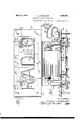
- FIG. 1 is a front elevational view of a preferred embodiment of my improved sign
- Fig. 2 is a plan sectional view taken along the line 22 of Fig. 1;
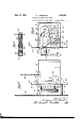
- Fig. 3 is an end view showing the way the sign may be mounted in a shop window
- Fig. 4 is a vertical sectional view taken along the line 44 of Fig. 2 looking in the direction of the arrows, and
- Fig. 5 is an enlarged view of the mounting means.
- the improved sign of my invention has been developed with the principal object in view of furnishing a stock sign carrying such well known words as Radio, Drugs, VVaffles or the like, and intended to be shown in the shop window or on a sign display in the front of the shop above the sidewalk. It was my purpose also to furnish stock signs of this character which could be produced for reasonable cost and shipped to a purchaser in such condition that the purchaser himself without expert help could install and use the sign. While the sign of my invention is preeminently adapted for such use the novel features employed may have a number of utilities in the general sign business whether used in the combination shown or not.
- the mounting posts for the tube are novel, serving as insulators between the mounting panel and glass, as a shock absorbing means to prevent breakage of the glass by the imparting of undue strain thereto, and the glass tubing is secured to the mounting posts by transparent cement which does not interfere with the light reflecting character of any portion of the tube.
- I provide a mounting panel 10 with flange portions 10a for reinforcing purposes, a rectangular housing 11 with flange portions 11a, and nuts and bolts 12 for securing the casing to the rear of the mounting panel.
- a transformer 13 is mounted by means of brackets 1414L secured by bolts 16.
- Mounting posts 17 and 18 with terminal posts 19 and 21 are provided on which thumb screws 22 and 23 are threaded for securing the leads to the output side of the transformer.
- a cable 24 supplies the transformer with current from a suitable commercial source.
- a plug 26 is secured having three contacts 27, 28 and 29, the contacts 27 and 28 being connected to conductors 31 and 32 leading to primary terminals 33 and 3 Contact 29 however,
- Plug 39 is connected to the opposite end of the cord and has contacts 41 and 42 adapted to be plugged into the usual wall socket, while a third conductor 43 is taken out from the rear of the plug and is adapted to be grounded.
- tubing 44 The usual type of tubing 44 is employed, shown here in the form of the word Radio and provided with electrodes 46 and 47 secured to high tension cables 48 and 49 leading from the transformer.
- electrodes 46 and 47 secured to high tension cables 48 and 49 leading from the transformer.
- Insulating liners 51 are provided for the protection and insulation of the entire sign.
- the posts 52 have threaded portions 520 on which the springs 53 are adapted to be turned to increase or decrease the over all length of the mounting po sr m ng he Pa t to the panel machine screws 56 are employed threaded into the hollow end of the posts 52.
- the tu n a i g po io 5 f the nt posts receivesthe tube 44 and a transparent cement 5 7 is employed to cement the tube in position.
- type of cement which have used most satisfactorily in this connection is the cellulose nitrate composition known generally under the name of pyralin.
- the principal intended use for the sign 0i my invention is to hang in suitable positions in retail shops, particularly in the window thereof.
- chains 58 on the end of which are small hooks 59.
- These chains are supported at suitable positions on the ceiling or the like and the hooks are fastened in any of a plurality of holes 61 arranged in thecasing 11.
- ter gravity of the sign as a whole is of course, below these holes and by suspending the entirely from this P sition the sign may inclined forwardly or backwardly depending upon which pair of holes the hooks 59 are engaged in.
- a I im is n a d. de t pr tec by Letters Patent of the United States is 1?"?
- a m ng devi e f m unt ng a eon t be n a p nel q pri i
- an insulating mounting post rigidly secures at one end to the panel the other end of the o bei g hr a d ha ed e slll s flfl ti ally encompassing three si es of a tube and leaving the other side 0 n, a tra xisparpnt cemen for securin the tll in s idhc i cement brid ing t, a open end oi t e arm p the U-shapefi member, and a helical spriig s cu d o said lip and t eade eve? threaded
Landscapes
- Physics & Mathematics (AREA)
- General Physics & Mathematics (AREA)
- Engineering & Computer Science (AREA)
- Theoretical Computer Science (AREA)
- Road Signs Or Road Markings (AREA)
Description
May 10, 1932- A. J. M MASTER SUPPORT FOR LUMINESCENT TUBES 2 Sheets-Sheet 1 Original Filed July 18, 1929 May 10, 1932. A. J. M MASTER SUPPORT FOR LUMINESCENT TUBES 2 Sheets-Sheet 2 Original Filed July 18, 1929 Patented. May 10, 1932 UNITED STATES PATENT OFFICE ARCHIE J. MCMASTER, OF CHICAGO, ILLINOIS, ASSIGNOR TO G-M LABORATORIES, IN- CORPORATED, OF CHICAGO, ILLINOIS, A CORPORATION OF ILLINOIS SUPPORT FOR LUMINESCENT TUBES Original application filed July 18, 1929, Serial No. 379,134. Divided and this application filed January 2,
1930. Serial My invention relates in general to electric signs and more in particular to the type of sign employing luminescent tubes and known in the trade generally by the term neon sign.
More specifically, my application is a division of my prior application, Serial No. 379,134, filed July 18, 1929.
The principal object of the present invention is the provision of an improved type of neon sign.
Another object is to provide an improved tube mounting which will not impart a strain to the glass.
Another object is the provision of an improved tube mounting adapted to be adjusted to support tubing at various distances from a panel.
Another object is the provision of a neon sign assembly arranged to be mounted easily and adjusted to position without danger of imparting strain to the glass.
Another object is the provision of a neon sign assembly wherein the tubing can be mounted at the place of manufacture and supported in such a way as to resist shocks and jars during transportation without endangering the tubing.
Other objects and features of the invention will be apparent from a consideration of the detailed description taken with the accompanying drawings, wherein Fig. 1 is a front elevational view of a preferred embodiment of my improved sign;
Fig. 2 is a plan sectional view taken along the line 22 of Fig. 1;
Fig. 3 is an end view showing the way the sign may be mounted in a shop window;
Fig. 4 is a vertical sectional view taken along the line 44 of Fig. 2 looking in the direction of the arrows, and
Fig. 5 is an enlarged view of the mounting means.
The improved sign of my invention has been developed with the principal object in view of furnishing a stock sign carrying such well known words as Radio, Drugs, VVaffles or the like, and intended to be shown in the shop window or on a sign display in the front of the shop above the sidewalk. It was my purpose also to furnish stock signs of this character which could be produced for reasonable cost and shipped to a purchaser in such condition that the purchaser himself without expert help could install and use the sign. While the sign of my invention is preeminently adapted for such use the novel features employed may have a number of utilities in the general sign business whether used in the combination shown or not.
The mounting posts for the tube are novel, serving as insulators between the mounting panel and glass, as a shock absorbing means to prevent breakage of the glass by the imparting of undue strain thereto, and the glass tubing is secured to the mounting posts by transparent cement which does not interfere with the light reflecting character of any portion of the tube.
Referring now briefly to the drawings with respect to the general features of the disclosure, I provide a mounting panel 10 with flange portions 10a for reinforcing purposes, a rectangular housing 11 with flange portions 11a, and nuts and bolts 12 for securing the casing to the rear of the mounting panel. A transformer 13 is mounted by means of brackets 1414L secured by bolts 16. Mounting posts 17 and 18 with terminal posts 19 and 21 are provided on which thumb screws 22 and 23 are threaded for securing the leads to the output side of the transformer. A cable 24 supplies the transformer with current from a suitable commercial source.
On the back of the mounting panel a plug 26 is secured having three contacts 27, 28 and 29, the contacts 27 and 28 being connected to conductors 31 and 32 leading to primary terminals 33 and 3 Contact 29 however,
is connected to a conductor 36, groundedwith one of the screws Plug 39 is connected to the opposite end of the cord and has contacts 41 and 42 adapted to be plugged into the usual wall socket, while a third conductor 43 is taken out from the rear of the plug and is adapted to be grounded.
The usual type of tubing 44 is employed, shown here in the form of the word Radio and provided with electrodes 46 and 47 secured to high tension cables 48 and 49 leading from the transformer. In making up the sign the apertures through which the electrodes extend are standardly placed, and accordingly the tube is doubled back at 44a and 44b in order to be extended through such apertures. Insulating liners 51 are provided for the protection and insulation of the entire sign.
. I mploy u u ual n n m ans for the tube 44 in the orm f moun n pos .2 having springs 53 secured at one end thereof and with U shape tube engaging means 54' at the outer end of the spring. The posts 52 have threaded portions 520 on which the springs 53 are adapted to be turned to increase or decrease the over all length of the mounting po sr m ng he Pa t to the panel machine screws 56 are employed threaded into the hollow end of the posts 52. The tu n a i g po io 5 f the nt posts receivesthe tube 44 and a transparent cement 5 7 is employed to cement the tube in position. type of cement which have used most satisfactorily in this connection is the cellulose nitrate composition known generally under the name of pyralin.
Her t r a u om ry s mploy t e portion of the tube connecting the letters for mounting purposes because wire or strips of metal were usually used to fasten the tube and this would show as a black spot on the sign. This manner of fastening is desirable because there is really only one part of the tube which is all in a single plane and that is the letters proper. With my mounting means I can connect to the letter portion of the tube and since this is all of equal hei ht the mounting operaion is i plifie xher a p ces 1 0W- ever where it s necessary to employ a mounting Q o n t ng Port on of th ube, pa t ular y Wh e th tub o n ct with e ermina A a vant Qf th typ m nting is that the tube ca be emove readily by the use of a suitable solvent which will dissolve the bond about the glass, or a sha p on be empl yed. o cu th ugh this pyralin band and free the tube.
The principal intended use for the sign 0i my invention is to hang in suitable positions in retail shops, particularly in the window thereof. In order to mount the sign I use chains 58, on the end of which are small hooks 59. These chains are supported at suitable positions on the ceiling or the like and the hooks are fastened in any of a plurality of holes 61 arranged in thecasing 11. The cen: ter gravity of the sign as a whole is of course, below these holes and by suspending the entirely from this P sition the sign may inclined forwardly or backwardly depending upon which pair of holes the hooks 59 are engaged in.
When a sign used in a store window it is generally advisable to hang it as close to the. Window as possible. I arrange for this and in order to protect the tube from actual contact with the window 62 I provide a plurality of spacing posts 63 formed of suitable material such as wood, four in number generally and arran ed in the manner shown. These spacing pos s are secured to the mounting panel in any suitable way as for example by screws 64.
The dvantage of he various features and h m nn r n which the sign is used pp a to be plain from the preceding description. In the claim I refer to neon signs for the sake of convenience but it is obvious that the reatures of the invention can be employed with any luminescent tube of this general character whether utilizing neon or not. The Various details described to bri g out t e novel features are illustrative any and invention is limited only the scope of t appended claim.
a I im is n a d. de t pr tec by Letters Patent of the United States is 1?"? In a eon ign, a m ng devi e f m unt ng a eon t be n a p nel q pri i an insulating mounting post rigidly secures at one end to the panel the other end of the o bei g hr a d ha ed e slll s flfl ti ally encompassing three si es of a tube and leaving the other side 0 n, a tra xisparpnt cemen for securin the tll in s idhc i cement brid ing t, a open end oi t e arm p the U-shapefi member, and a helical spriig s cu d o said lip and t eade eve? threaded portion of sa d ,ost.
1 1 itness whereof, e lnm subsc be y name this 1. O n w J- MQMABTE -f
Priority Applications (1)
| Application Number | Priority Date | Filing Date | Title |
|---|---|---|---|
| US417996A US1858053A (en) | 1929-07-18 | 1930-01-02 | Support for luminescent tubes |
Applications Claiming Priority (2)
| Application Number | Priority Date | Filing Date | Title |
|---|---|---|---|
| US379134A US1858052A (en) | 1929-07-18 | 1929-07-18 | Sign |
| US417996A US1858053A (en) | 1929-07-18 | 1930-01-02 | Support for luminescent tubes |
Publications (1)
| Publication Number | Publication Date |
|---|---|
| US1858053A true US1858053A (en) | 1932-05-10 |
Family
ID=27008489
Family Applications (1)
| Application Number | Title | Priority Date | Filing Date |
|---|---|---|---|
| US417996A Expired - Lifetime US1858053A (en) | 1929-07-18 | 1930-01-02 | Support for luminescent tubes |
Country Status (1)
| Country | Link |
|---|---|
| US (1) | US1858053A (en) |
-
1930
- 1930-01-02 US US417996A patent/US1858053A/en not_active Expired - Lifetime
Similar Documents
| Publication | Publication Date | Title |
|---|---|---|
| US1570980A (en) | Illuminated sign | |
| ES2109291T3 (en) | FLAT-MOUNTED FLAT INDICATOR ELEMENT FOR ELEVATORS. | |
| US1858053A (en) | Support for luminescent tubes | |
| US2648152A (en) | Illuminated house number | |
| US1878229A (en) | Fixture for vacuum tube lights | |
| US1844097A (en) | Interchangeable element electric illuminated sign | |
| US1536407A (en) | Tail-light support | |
| US1850319A (en) | Advertising sign | |
| US2018874A (en) | Indicator light | |
| US1951502A (en) | Gaseous signal light | |
| US1858052A (en) | Sign | |
| US2274682A (en) | Luminous sign | |
| US2071699A (en) | Tube socket | |
| US1764687A (en) | Light-reflector sign and signal | |
| US1804525A (en) | Gas lamp socket and transformer | |
| US2203785A (en) | Illuminated license plate and case therefor | |
| US4019170A (en) | Adapter unit for pedestrian traffic control signal | |
| US1794954A (en) | Illuminated sign | |
| US1867836A (en) | Support for neon signs | |
| US977081A (en) | Electric street-indicating sign. | |
| US1052182A (en) | Electric sign. | |
| US1932509A (en) | Gas lamp | |
| US1986009A (en) | Composite luminescent tube panel system | |
| US1947763A (en) | Illuminating attachment | |
| US1827275A (en) | Neon sign |