US1052182A - Electric sign. - Google Patents
Electric sign. Download PDFInfo
- Publication number
- US1052182A US1052182A US68224812A US1912682248A US1052182A US 1052182 A US1052182 A US 1052182A US 68224812 A US68224812 A US 68224812A US 1912682248 A US1912682248 A US 1912682248A US 1052182 A US1052182 A US 1052182A
- Authority
- US
- United States
- Prior art keywords
- sign
- board
- letter
- bars
- letters
- Prior art date
- Legal status (The legal status is an assumption and is not a legal conclusion. Google has not performed a legal analysis and makes no representation as to the accuracy of the status listed.)
- Expired - Lifetime
Links
- 101150010783 Aard gene Proteins 0.000 description 1
- 150000001768 cations Chemical class 0.000 description 1
- BFPSDSIWYFKGBC-UHFFFAOYSA-N chlorotrianisene Chemical compound C1=CC(OC)=CC=C1C(Cl)=C(C=1C=CC(OC)=CC=1)C1=CC=C(OC)C=C1 BFPSDSIWYFKGBC-UHFFFAOYSA-N 0.000 description 1
- 238000010276 construction Methods 0.000 description 1
Images
Classifications
-
- G—PHYSICS
- G09—EDUCATION; CRYPTOGRAPHY; DISPLAY; ADVERTISING; SEALS
- G09F—DISPLAYING; ADVERTISING; SIGNS; LABELS OR NAME-PLATES; SEALS
- G09F13/00—Illuminated signs; Luminous advertising
Definitions
- This invention relates to improvements in electric signs of the kind which comprise a board and a plurality of interchangeable sign letters carrying electric lamps which outline them, each letter being. separable from the board and being adapted to be atthat may be changed at will, and including electric connections bv means ofwhich the' lamp circuits of the letters may be detachably connected to a main circuit carried-by the sign board.
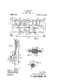
- FIG. 1 is a view in front elevation of an electric sign provided with my improvements
- Fig. 2 is a view rep-v resenting on an enlarged scale a vertical section through the sign in a plane indicated by the line ⁇ 2-2 of Fig. ⁇ 1
- Fig. is a view representing a longitudinal, centlal section through a detachable plug device by means of which the electric circuit of the lamps on a sign letter are connected with the main circuit carried by the sign
- Fig. 4 is a view representing a: transverse section through said plug in 'a plane indicated by the line 4-4 of Fig. y3.
- 10 indicates the supporting board which forms the main body of the sign and :which is,
- Each letter comprises a hollow body 11a which carries on yits front face, in a familiar manner, ⁇ a plurality of sockets 11b in which .are secured electric lamps or bulbs 11"'.
- a horizontally extending rod 12 ⁇ which is #ed by the sign board.
- said rod 1s supported by eye-bolts 13, 13, which are screwed into the sign-board.
- Eachletter 14 so located as tol suspend the i letter in proper vertical position with its back against the front face of the sign-board and adapted bo be engaged upon the rod 12.
- a hori ⁇ zontally extendingy slot 15 is formed inthe ported a pair of verticallyspaced, longitu- 'dinally extending, horizontal bus-bars 16,16, which comprise the terminals of the main electric circuit which is carried by the signboard and is intended to supply current to the lamps on the sign letters.
- Said bus-bars are carried by vertically spaced, horizontal arms 17, 17, extending rearwardly from the si,i','n-boardv and secured to insulatingvblocks l 18.
- Said insulating'blocks are in turn carried by a horizontalv bar 19 which extends, parallel ⁇ to and longitudinally of the sign-l board and is supported by open brackets 20 that stra-ddle said bar and are rigidly ⁇ secured to the rear face of the sign board.
- Said apron indicates a shield or apron adapted for protecting the bus-bars 16 from rain, snow and the like.
- Said apron has an upper marginal part 21a which engages closely against -the rear, face ofthe sign-board l0 along a line vspaced above the level of the said busbars a downwardly and rearwardly inclined part 21b-which'is secured to and rests-upon the upper arms of the brackets 20 and a vertical part'21 which depends atv the lrear ot the level thereof.
- the bus-bars are thus protected: from rain, snow and the like which inclined or horizontal direction against the back ofthe sign.
- the line wires of the circuit intended to supply the lamps of the let- .ters are connected in a familiar manner with the bus-bars 16,' 16.
- connectionV between the main circuit carried by the' sign-board and the circuit connectedy to the lamps carried by a letter. Said the bus-bars and projectss considerably below spaced a short dist-ance from and is support- ,i
- sup-v 22 indicates a plug attachment for' making land running around the a number of plugs 22 are termediate part 22a of the plug in the respec-H tive planes of the upper and lower faces of the said reduced end parts 22h, 22%
- a 25, 25 indicate flat contact bars whlch eX- tend the full length of' the plug with their intermediate parts extending through the slots 23, 23 and their end partsin engagen ment with the opposite faces ot the reduced ends of the plug.
- rllhe bars 25, 25 have sharpened front ends 25, 25a, and are slightly bent or bowed adjacent said ends away from the reduced forward end part 22", so as to rovide for spring engagement of the said plug end withln a spring socket 26 comprising the two contacts of the cir cuit of a letter.
- rlhe rear wall et the si 'i letter has an aperture in line with said socket througliwhich the plug may be inserted ⁇ in order to engage it within said socket.
- rllie rear ends of the bars 25 are fiat and the reduced end 22b of the plug is so proportioned inthickness that when the plug is inserted between the bus-bars 16, 16, the rear ends of the contact bars 23, 23 will engage between the said bus-bars and make good electric contact.
- the letter may be placed at any point on the p face of the sign in one or the other of the lines they are intended to occupy Wit-hout the necessity of paying any attention whatever to the proper connection between the main electric circuit and the lamp circuit of the letter. rlhe words or letters on a sign may thus be removed and replaced to form c a new combination with great rapidity and ease.
- an electric sign in combination with a board and a plurality of electrically i1luminated letters supported thereon at the front, said board being provided with a slot defining a line in which said letters may be V arranged, parallel spaced contact bars con ⁇ stituting terminals of a main circuit, said contact bars being located back of said board and extending parallel to and directly behind said slot, an electric-socket provided in each letter, a plurality of contact plugs extending through the slot in the board, one for each letter, said plugs being engaged at one end between said contact bars and at the other end being adapted for detachable engagement with the socket of one of a marginal part secured in close contact with the rear face of said board and extending over and depending at the rear ot said contact bars.
Landscapes
- Physics & Mathematics (AREA)
- General Physics & Mathematics (AREA)
- Engineering & Computer Science (AREA)
- Theoretical Computer Science (AREA)
- Illuminated Signs And Luminous Advertising (AREA)
Description
L. G. SHEPARD.
ELECTRIC SIGN.
APPLICATION FILED MAR. 7. 1912.
aard
Patented Feb. 4, 1913.
. tached to the face of the board to' form wordsA `UNiTED STATES PATENT OFFICE.-
LEONARD G. SHEPARD, 0F EVANSTON, ILLINOIS, ASSIGNOR T0 FEDERAL SIGN SYSTEM ELECTRIC, A CORPORATION 0F NEW YORK. I
Specication of Letters Patent.
ELECTRIC SIGN..
Patented Feb. 4, 1913.
Application le Iarch 7, 1912. ASerial No. 682,248.
To all 'whomz'tmay concern.'
Be it known that I, LEONARD G. SHEPABD,
la citizen of the United States, and a resident of Evanston, in the county of Cook and State of Illinois, have invented certainnew and usethereon, which form a part of this speci cation.
This invention relates to improvements in electric signs of the kind which comprise a board and a plurality of interchangeable sign letters carrying electric lamps which outline them, each letter being. separable from the board and being adapted to be atthat may be changed at will, and including electric connections bv means ofwhich the' lamp circuits of the letters may be detachably connected to a main circuit carried-by the sign board.
The invention consists of the matters .hereinafter described and more particularly pointed out in the appended claims.
In the drawings-Figure 1 is a view in front elevation of an electric sign provided with my improvements; Fig. 2 is a view rep-v resenting on an enlarged scale a vertical section through the sign in a plane indicated by the line`2-2 of Fig.` 1; Fig. is a view representing a longitudinal, centlal section through a detachable plug device by means of which the electric circuit of the lamps on a sign letter are connected with the main circuit carried by the sign; and Fig. 4 is a view representing a: transverse section through said plug in 'a plane indicated by the line 4-4 of Fig. y3.
Referring now to that embodiment of my invention illustrated in the drawings, 10 indicates the supporting board which forms the main body of the sign and :which is,
. descends vertically or which is driven in an 11` indicates a plurality of letters, in thisV adapted for the support of the sign letters.
case arranged to spell the words Special sale. Each letter, as shown, comprises a hollow body 11a which carries on yits front face, in a familiar manner,` a plurality of sockets 11b in which .are secured electric lamps or bulbs 11"'. Y Y
For each line of lettering that4 is intended to appear on the sign, there is provided a horizontally extending rod 12` which is #ed by the sign board. As shown herein, said rod 1s supported by eye- bolts 13, 13, which are screwed into the sign-board. Eachletter 14 so located as tol suspend the i letter in proper vertical position with its back against the front face of the sign-board and adapted bo be engaged upon the rod 12. Each letter the sign-board.
For each line of letters and spacedvertically below each supporting rod 12, a hori `zontally extendingy slot 15 is formed inthe ported a pair of verticallyspaced, longitu- 'dinally extending, horizontal bus- bars 16,16, which comprise the terminals of the main electric circuit which is carried by the signboard and is intended to supply current to the lamps on the sign letters. Said bus-bars are carried by vertically spaced, horizontal arms 17, 17, extending rearwardly from the si,i','n-boardv and secured to insulatingvblocks l 18. Said insulating'blocks are in turn carried by a horizontalv bar 19 which extends, parallel `to and longitudinally of the sign-l board and is supported by open brackets 20 that stra-ddle said bar and are rigidly `secured to the rear face of the sign board.
21 indicates a shield or apron adapted for protecting the bus-bars 16 from rain, snow and the like. Said apron has an upper marginal part 21a which engages closely against -the rear, face ofthe sign-board l0 along a line vspaced above the level of the said busbars a downwardly and rearwardly inclined part 21b-which'is secured to and rests-upon the upper arms of the brackets 20 and a vertical part'21 which depends atv the lrear ot the level thereof. The bus-bars are thus protected: from rain, snow and the like which inclined or horizontal direction against the back ofthe sign. The line wires of the circuit intended to supply the lamps of the let- .ters are connected in a familiar manner with the bus-bars 16,' 16.
the connectionV between the main circuit carried by the' sign-board and the circuit connectedy to the lamps carried by a letter. Said the bus-bars and proiects considerably below spaced a short dist-ance from and is support- ,i
11 is provided at its upper end with a hook may thus be attached to or detachedfrom l sign board. Back of the sign-board and in horizontal alinement with each slot are sup-v 22 indicates a plug attachment for' making land running around the a number of plugs 22 are termediate part 22a of the plug in the respec-H tive planes of the upper and lower faces of the said reduced end parts 22h, 22% A 25, 25 indicate flat contact bars whlch eX- tend the full length of' the plug with their intermediate parts extending through the slots 23, 23 and their end partsin engagen ment with the opposite faces ot the reduced ends of the plug. rllhe bars 25, 25 have sharpened front ends 25, 25a, and are slightly bent or bowed adjacent said ends away from the reduced forward end part 22", so as to rovide for spring engagement of the said plug end withln a spring socket 26 comprising the two contacts of the cir cuit of a letter. rlhe rear wall et the si 'i letter has an aperture in line with said socket througliwhich the plug may be inserted `in order to engage it within said socket. rllie rear ends of the bars 25 are fiat and the reduced end 22b of the plug is so proportioned inthickness that when the plug is inserted between the bus- bars 16, 16, the rear ends of the contact bars 23, 23 will engage between the said bus-bars and make good electric contact.
The annular body of the plug is provided with rounded grooves 22d and rounded ribs 22e separating said grooves so that any moisture or rain which falls or trickles loctween the back of the associated letter and front tace of the signboard and falls upon the plug will be directed into said grooves plug will drip from the lower side thereof,
ln the use of my improved attraction sign, provided and also a plurality of sign letters. lln placing the letters on the sign-board the forward end of the plug is first inserted through the aperture in the rear wall of the sign letter into the socket carried thereby. 'lhe letter is, by its hook, then hung 1n the intended position on one of the supporting rods l2, and is swung backwardly so as to bring its rear face a ainst the sign-board by which movement t e rear end caused to engage between thns roviding electrical connection between said lis-bars constituting the terminals of the main electric circuit and the terminals said letters, and an apron havin of the plug 22 is the busbars 16,
notarse in the socket 26 of the lamp circuit of the letter.` In my improved construction the letter may be placed at any point on the p face of the sign in one or the other of the lines they are intended to occupy Wit-hout the necessity of paying any attention whatever to the proper connection between the main electric circuit and the lamp circuit of the letter. rlhe words or letters on a sign may thus be removed and replaced to form c a new combination with great rapidity and ease.Y
ll claim as my invention l. ln an `electric sign, in combination with a board and a plurality of electrically illuminated letters supported thereon at the front, parallel spaced contact bars constituting terminals of a main circuit located back of said board and extending parallel to aline along which the letters are to be arranged, said board being provided with a slot or opening in front of said contact bars, an electric socket provided in each letter, and aplurality of contact plugs eX- tending through the slot or opening in the board, one for each letter, said plugs being engaged at one end between said contact bars and at the other end being adapted for detachable engagement with the socket ot' one of said letters.
2. ln an electric sign, in combination with a board and a plurality of electrically i1luminated letters supported thereon at the front, said board being provided with a slot defining a line in which said letters may be V arranged, parallel spaced contact bars con` stituting terminals of a main circuit, said contact bars being located back of said board and extending parallel to and directly behind said slot, an electric-socket provided in each letter, a plurality of contact plugs extending through the slot in the board, one for each letter, said plugs being engaged at one end between said contact bars and at the other end being adapted for detachable engagement with the socket of one of a marginal part secured in close contact with the rear face of said board and extending over and depending at the rear ot said contact bars.
intestimony, that ll claim the foregoing as my invention l aliix my signature in the4 presence of two witnesses, February A. D. i912.
LEONARD Gr. SHEPARD.
this 20th day of Witnesses:
CLARENCE E. Mnnnnoru, Grosor: llt. Winnins.
Priority Applications (1)
| Application Number | Priority Date | Filing Date | Title |
|---|---|---|---|
| US68224812A US1052182A (en) | 1912-03-07 | 1912-03-07 | Electric sign. |
Applications Claiming Priority (1)
| Application Number | Priority Date | Filing Date | Title |
|---|---|---|---|
| US68224812A US1052182A (en) | 1912-03-07 | 1912-03-07 | Electric sign. |
Publications (1)
| Publication Number | Publication Date |
|---|---|
| US1052182A true US1052182A (en) | 1913-02-04 |
Family
ID=3120443
Family Applications (1)
| Application Number | Title | Priority Date | Filing Date |
|---|---|---|---|
| US68224812A Expired - Lifetime US1052182A (en) | 1912-03-07 | 1912-03-07 | Electric sign. |
Country Status (1)
| Country | Link |
|---|---|
| US (1) | US1052182A (en) |
-
1912
- 1912-03-07 US US68224812A patent/US1052182A/en not_active Expired - Lifetime
Similar Documents
| Publication | Publication Date | Title |
|---|---|---|
| US2006436A (en) | Electric current subdividing connecting device | |
| US3221432A (en) | Illuminated sign | |
| US2853819A (en) | Electric signs | |
| US1875563A (en) | Display stand | |
| US1844097A (en) | Interchangeable element electric illuminated sign | |
| US1052182A (en) | Electric sign. | |
| US2336016A (en) | Advertising device | |
| US1120876A (en) | Sign. | |
| US2245885A (en) | Lighting device | |
| US1504826A (en) | Insert-card frame | |
| US2274682A (en) | Luminous sign | |
| US1197736A (en) | Coin-holder. | |
| US1782564A (en) | Electric sign | |
| US1246500A (en) | Sign device or apparatus. | |
| US1775151A (en) | Display fixture | |
| US1794954A (en) | Illuminated sign | |
| US867635A (en) | Electric sign. | |
| US1626958A (en) | Illuminated sign | |
| US1330677A (en) | Electric sign | |
| US1918616A (en) | Double faced sign | |
| US702149A (en) | Switchboard for illuminating electric-lamp signs. | |
| US1858053A (en) | Support for luminescent tubes | |
| US1498263A (en) | Sign | |
| US2129519A (en) | Display device | |
| US2996821A (en) | Illuminated display device |