US1858052A - Sign - Google Patents
Sign Download PDFInfo
- Publication number
- US1858052A US1858052A US379134A US37913429A US1858052A US 1858052 A US1858052 A US 1858052A US 379134 A US379134 A US 379134A US 37913429 A US37913429 A US 37913429A US 1858052 A US1858052 A US 1858052A
- Authority
- US
- United States
- Prior art keywords
- sign
- tube
- panel
- mounting
- transformer
- Prior art date
- Legal status (The legal status is an assumption and is not a legal conclusion. Google has not performed a legal analysis and makes no representation as to the accuracy of the status listed.)
- Expired - Lifetime
Links
Images
Classifications
-
- G—PHYSICS
- G09—EDUCATION; CRYPTOGRAPHY; DISPLAY; ADVERTISING; SEALS
- G09F—DISPLAYING; ADVERTISING; SIGNS; LABELS OR NAME-PLATES; SEALS
- G09F13/00—Illuminated signs; Luminous advertising
- G09F13/26—Signs formed by electric discharge tubes
Definitions
- Myinveiition relates in general to electric signs and more in particular to'the type' of electric sign employing luminescent tubesa and knownin the trade Neon-sign.
- the type of mounting employed is generally determined by thelocation in which'thesign is to'be u'sed.
- Another object is to provide a sign mounting of an improved character which will not imparta strain to the glass.
- Another object is the production of a assembly which may be standardized for use" with substantially all classes of signs.
- Another object is :the provision of'a sign mounting wherein all of the high tension wires are fully protected andfconcealedg'1"
- Another object is toproduce a'peon'sign;
- Another 'obj ect is the production'of a i eon sign which, can be mountedfor operation, by
- Another object is the provision of; a neon sign assembly. which is arranged to be mounted'easily and adjusted to'position inaccordance with its elevation;
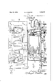
- a i F ig. 1 is a 'front elevational view of a preferred'embodiment of my improved sign
- Fig. 3 is an end view showing thewaythe sign may be mounted in a shop window
- Fig. 4 is a vertical sectional view, taken 3 along the line'4-45 of Fig. 2 looking in the direction jof th'elarioWs, and "F 1g: 5 is an enlarged v ew of the means. I;
- The;- improved sign'ofmy invention has been developed withxthe principal object in view of'f urnishing a stock sign carrying such. well known words as 'Radio, -D rugs,' Wafilesfl or the like, and intended'to be-ishown in the shop window; or on a sign display inthe front of theshop above thesidewalk. It was my purpose "also to furnislrstock signs of this character which could be produced for reasonablecdst and-shipped to a purchaser in such conditionthat the purchaser himself without expert help could installaii'd use the sign. iVVhi'le the sign of my invention is preeminentlyadapted forgsuch-usethe novel features employed may have anumber of utili ties in the general sign business whether used in the combination shown or not. 7
- invention-I Considering firstthe j general features of the "invention-I provide amounting panel of considerablestrength and made generally of reinforced she et' steel the back of which'car ries a 'ca'sing housing the transformeqand the front of which serves'as a background for theluminescent tube sign.
- the terminals of thetube run "into; the casing at the back of mounting thmp 'ntin'g panel andconnect to the transloo .
- the transformer is mountedwithina suita ble housing which appears in the drawings and high tension terminals are. providedat the ends thereof in the form'of vitreous mounting posts 17 and 18 through which terminal posts 19 and QlIPIOject and on which thumb ⁇ screws 22 and 23 are threaded for securing the 'high tensiontuhe leadsto the output side of the transformer.
- the transformer 13 is designed to operatcwith standard commercialalternating' *cur:
- rentandha source of current is connectedto theprimary side of the transformerby suitable'cable 24.
- Thejterminal 28 however,
- the socket 38 at one end ofthe cord ;24 is'of a three way type and adapted to engage with the plug 26; A plug 39 is connected to the;
- thejsign iproper at front of the mounting.- panel I show the. usual type of tubing 44 making up the word Radio and the tube being provided with electrodes 46 and 47 ofany suitable
- the se elec trodes have secured -thereto v high tension cables 48 and 49 adapted to be secured to the output terminals of the transformer 13.
- the tube is so constructed that the distance between the terminals 46 and 47 is standardized and will also be substantially in line with the high tension transformer terminals so that they can be readily connected thereto. This means that if the sign is long the tube will have to be doubled back substantially at 44a and 44b in order-to beextended through the 'standardly placed apertures in the mounting panel. Rubber insulating liners 51" are provided around these holes for the further protection and insulation of the entire sign.
- the tube 44in the form of mounting posts 52 having springs 53 secured at one end thereof and with U shape tube engagingmeans 54 at the outer end of the spring.
- the posts 52 have threaded portions 52a on which the springs 53 are adapted to be turned to increase or decrease the over all length of the mounting posts.
- machine screws 56 are employed threaded into the hollow end of the posts 52.
- the tube engaging portion .54ofthe mounting posts receives the tu be.44 and a transparent cement 57 is employed-to cementthe tube in position.
- the type of cement which I have used most satisfactorily in this connection is the cellulose nitrate composition known generally under the name of pyralin'.
- V is all. in a single plane and that is the letters center of gravity of the sign as a whole is of course below these holes andbysuspending the sign entirely from this position the sign may be inclined forwardly or backwardly depending upon which pair of holes the hooks 59 are engaged in.
- ⁇ Vhen a sign is used in a store window it is generally advisable to hang it as close to the window as possible. I arrange for this and in order to protect the tube from actual contact with the window 62 I provide a plurality of spacing posts 63 formed of suitable materialsuch as wood, four in number generally and arranged in the manner shown. These spacing posts are secured to the mounting panel in any suitable way as for example by screws 64.
- a neon sign a mounting panel, a transformer mounted on one side thereof, a luminescent tube, means for resiliently mounting said tube on the opposite side of the panel, terminal members for said tube, said panel having apertures through which the terminal members extend, the terminal members being supported only by the tube to permit movement thereof upon expansion and contraction of the tube, and a flexible conductor connecting the terminal members with the transformer.
- a mounting panel a luminescent tube, means for resiliently mounting said tube on the front side of the panel, a transformer mounted on the opposite side of the panel, said panel having a pair of apertures adjacent opposite ends of the transformer, a terminal member on each end of said tube, the ends of the tube being bent to project through said apertures, an insulating washer in said apertures surrounding the tube and spaced therefrom whereby the entire tube is resiliently mounted, andconductors for connecting the terminal members of the tubes to the output of the transformer.
- a metallic mounting panel a metallic casing secured to the back of saidpanel, a transformer mounted in said casing, said transformer having output terminals at its opposite ends, a grounded conductor connected to said panel whereby the panel and casing are mounted at ground potential, a luminescent tube resiliently mounted on said panel, the ends of said tube extend close proximity to said transformer termiback thereof, suspension means for suspend-' ing'the panel in a vertical position, and spacing posts extending from the front face of the panel for spacing the luminescent tube from a window and preventing contact therewith.
- a neon sign a mounting panel, a floating luminescent tube secured thereto, the ends of said tube being bent and extending through said panel but spaced therefrom, terminal'members on the ends of said tube, a transformer mounted on the back of said panel andhaving output terminals extending laterally therefrom into close proximity to the tube ends and flexible leads connecting the tube ends and transformer terminals.
- a mounting panel having apertures in its face, a floating luminescent tube securedv thereto and spaced therefrom, said tube being doubled back from the letter forming portion and having its ends bent to loosely extend through the apertures I ing into opposite endsof the casing and into
Landscapes
- Physics & Mathematics (AREA)
- General Physics & Mathematics (AREA)
- Engineering & Computer Science (AREA)
- Theoretical Computer Science (AREA)
- Illuminated Signs And Luminous Advertising (AREA)
Description
May 10, 1932. McMASTER v 1,858,052
' SIGN Filed July 18, 1929 2 Sheets-Sheet 1 N N I 7 c 7 & W3],
May 10, 1932- A. J. M MASTER 1,858,052
SIGN
Filed July 18, 1929 2 Sheets-Sheet 2 w Q A a N [Milli Patented May 10, 1932 EARCHIE J. cMAsTER, on. CHICAGO, innmois. AssIqnoR-mo' G M V 7 QFGI-IICAGQILLINOIS LABORATORIES, me,
' 'sien Application filed Ju'i is ,"1929; Seria1 No. 3 79,134.
Myinveiition relates in general to electric signs and more in particular to'the type' of electric sign employing luminescent tubesa and knownin the trade Neon-sign.
These signs are produced by forming glass tubes to the shape of the letters-or other dicia which will appear .on thesign exhausting the tubes introducing a'small quantity of a rare or inert gas which by m'eansof suitable electrodes may be madeto carry a current of; high pressureresulting in a glow in the tub-; ing. This tubing is mounted on a suitable M support'for either inside or outside use, and
the type of mounting employed is generally determined by thelocation in which'thesign is to'be u'sed.
There are many problemsencounterediii- M ths manufacture, installation anduse of signs of this character; these problems occurring principally on account; of the fragile characterof the glass" tubing, the use of a high voltage, etc. The character of the curi i rent employed introduces fire and injury hazards which are ofgreat importance when the I sign is to be used. for inside display as for example in a shop window;
Accordingly the principal'object of my 7 present invention ,is' to overcome all of theobjections heretofore encountered in the manufacture, installation and use of neon signs.
Another object is to provide a sign mounting of an improved character which will not imparta strain to the glass.
Another object is the production of a assembly which may be standardized for use" with substantially all classes of signs.
Another object is :the provision of'a sign mounting wherein all of the high tension wires are fully protected andfconcealedg'1" Another object is toproduce a'peon'sign;
which will pass allthe tests laid downfat the present time by Underwriters Laboratories for general electrical apparatus.
Another 'obj ect is the production'of a i eon sign which, can be mountedfor operation, by
the ordinary shop keeper without the ser v' i-formei *by two short-high; tension cables ices of an electrician or other expert..
1 Anotherobject the provision of aiieon Sign of a unitary character and adapted for generally by the term any usual type o'finside or outside display. Another object is the provision of; a neon sign assembly. which is arranged to be mounted'easily and adjusted to'position inaccordance with its elevation;
tion will be apparent from a consideration of'the detailed description taken with the accompanying drawings wherein a i F ig. 1 is a 'front elevational view of a preferred'embodiment of my improved sign;
. 5* Otherobjects and features of the inven Fig; 2-isa plan sectional view taken along y the line 2.2aof 1; I
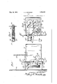
Fig. 3 is an end view showing thewaythe sign may be mounted in a shop window;
Fig. 4 isa vertical sectional view, taken 3 along the line'4-45 of Fig. 2 looking in the direction jof th'elarioWs, and "F 1g: 5 is an enlarged v ew of the means. I;
The;- improved sign'ofmy invention has been developed withxthe principal object in view of'f urnishing a stock sign carrying such. well known words as 'Radio, -D rugs,' Wafilesfl or the like, and intended'to be-ishown in the shop window; or on a sign display inthe front of theshop above thesidewalk. It was my purpose "also to furnislrstock signs of this character which could be produced for reasonablecdst and-shipped to a purchaser in such conditionthat the purchaser himself without expert help could installaii'd use the sign. iVVhi'le the sign of my invention is preeminentlyadapted forgsuch-usethe novel features employed may have anumber of utili ties in the general sign business whether used in the combination shown or not. 7
= Considering firstthe j general features of the "invention-I provide amounting panel of considerablestrength and made generally of reinforced she et' steel the back of which'car ries a 'ca'sing housing the transformeqand the front of which serves'as a background for theluminescent tube sign. The terminals of thetube run "into; the casing at the back of mounting thmp 'ntin'g panel andconnect to the transloo . tween the mounting panel and glass, as a shock absorbing means to prevent breakage of the glass by the imparting of undue strain thereto, and the glass tubing is secured to the mounting posts by transparent cement which does not interfere with the light re.- flecting character of any portion of the .;tube.
Referring now to the drawings and considering the details of the invention I provide a' mounting panellO having flange edges 10a for reinforcing purposes, this panel preferably being formed of sheet steel and finished in any suitable color and design. At the back by suitable fastening meanssuch as bolts 16.
The transformer is mountedwithina suita ble housing which appears in the drawings and high tension terminals are. providedat the ends thereof in the form'of vitreous mounting posts 17 and 18 through which terminal posts 19 and QlIPIOject and on which thumb {screws 22 and 23 are threaded for securing the 'high tensiontuhe leadsto the output side of the transformer. 1 The transformer 13 is designed to operatcwith standard commercialalternating' *cur:
9 design, for this purpose.
On the back of th mounting-panel aplug'.
rentandha source of current is connectedto theprimary side of the transformerby suitable'cable 24. I arrange-to ground the entire Isign frame however, to avoid any. possibility of accident andl employ'the'cable 24which is of course then made of special 26 is secured havingthree contacts 27, 28 and 29,th e contacts 27 and 28 being connected to conductors. 31 and 32 leading to primary terminals 33 and 34 respectively on the trans former housing. Thejterminal 28, however,
is connected to a conductor 36; which is.
grounded with one of the screws 37 (Fig. The socket 38=at one end ofthe cord ;24 is'of a three way type and adapted to engage with the plug 26; A plug 39 is connected to the;
opposite endof the cord-and has. contacts41 and .42 adapted to plug into the iusuahwall socket, :while a third conductor 43 isjtajken;
out from the rear of theplug and isadapted to be grounded by suitable means such for example as the usual fastening screw (not. shown) on the usual .outletplug escutcheon plate.(.-not shown). 1
Now referring to thejsign iproper at front of the mounting.- panel I show the. usual type of tubing 44 making up the word Radio and the tube being provided with electrodes 46 and 47 ofany suitable The se elec trodes have secured -thereto v high tension cables 48 and 49 adapted to be secured to the output terminals of the transformer 13. The tube is so constructed that the distance between the terminals 46 and 47 is standardized and will also be substantially in line with the high tension transformer terminals so that they can be readily connected thereto. This means that if the sign is long the tube will have to be doubled back substantially at 44a and 44b in order-to beextended through the 'standardly placed apertures in the mounting panel. Rubber insulating liners 51" are provided around these holes for the further protection and insulation of the entire sign.
1 I employ unusual mounting means for the tube 44in the form of mounting posts 52 having springs 53 secured at one end thereof and with U shape tube engagingmeans 54 at the outer end of the spring. The posts 52 have threaded portions 52a on which the springs 53 are adapted to be turned to increase or decrease the over all length of the mounting posts. For mounting the posts to the panel; machine screws 56 are employed threaded into the hollow end of the posts 52. The tube engaging portion .54ofthe mounting posts receives the tu be.44 and a transparent cement 57 is employed-to cementthe tube in position. The type of cement which I have used most satisfactorily in this connection is the cellulose nitrate composition known generally under the name of pyralin'. Heretofore it was customary to employ the portion of the tube connecting the letters for mounting purposesbecause wire or strips of metal were usually used to fasten'the tube and this would show as a black spot on the sign. This manner of fastening is desirable because there is really only one part of the tube which through this pyralin b and and free the tube The principal intended use for the. sign of my invention is to hang in suitable positions in retail shops, particularly in the window thereof. v In order tomount the signI use chains 58 onthe end of which are small hooks 59,,Thesechains are supported at suitable positions on the ceiling or the like and the hooks are fastened .in any of a plurality of holes 61 arranged inthe :casing '11. The.
V is all. in a single plane and that is the letters center of gravity of the sign as a whole is of course below these holes andbysuspending the sign entirely from this position the sign may be inclined forwardly or backwardly depending upon which pair of holes the hooks 59 are engaged in.
\Vhen a sign is used in a store window it is generally advisable to hang it as close to the window as possible. I arrange for this and in order to protect the tube from actual contact with the window 62 I provide a plurality of spacing posts 63 formed of suitable materialsuch as wood, four in number generally and arranged in the manner shown. These spacing posts are secured to the mounting panel in any suitable way as for example by screws 64.
The advantages of the various features and the manner in which the sign is used appear to be plain from the precedingdescription. In the claims I refer to neon signs for the sake of convenience but it is obvious that the features of the invention can be employed with any luminescent tube of this general character whether utilizing neon or not. The 7 various details described to bring out the novel features are illustrative only and the invention is limited only by the scope of the appended claims.
IVhat I claim as new and desire to protect by United States Letters Patent is:
1. In a neon sign, a mounting panel, a transformer mounted on one side thereof, a luminescent tube, means for resiliently mounting said tube on the opposite side of the panel, terminal members for said tube, said panel having apertures through which the terminal members extend, the terminal members being supported only by the tube to permit movement thereof upon expansion and contraction of the tube, and a flexible conductor connecting the terminal members with the transformer.
2. In a neon sign, a mounting panel, a luminescent tube, means for resiliently mounting said tube on the front side of the panel, a transformer mounted on the opposite side of the panel, said panel having a pair of apertures adjacent opposite ends of the transformer, a terminal member on each end of said tube, the ends of the tube being bent to project through said apertures, an insulating washer in said apertures surrounding the tube and spaced therefrom whereby the entire tube is resiliently mounted, andconductors for connecting the terminal members of the tubes to the output of the transformer.
3. In a neon sign, .a metallic mounting panel, a metallic casing secured to the back of saidpanel, a transformer mounted in said casing, said transformer having output terminals at its opposite ends, a grounded conductor connected to said panel whereby the panel and casing are mounted at ground potential, a luminescent tube resiliently mounted on said panel, the ends of said tube extend close proximity to said transformer termiback thereof, suspension means for suspend-' ing'the panel in a vertical position, and spacing posts extending from the front face of the panel for spacing the luminescent tube from a window and preventing contact therewith.
5. In a neon sign, a mounting panel, a floating luminescent tube secured thereto, the ends of said tube being bent and extending through said panel but spaced therefrom, terminal'members on the ends of said tube, a transformer mounted on the back of said panel andhaving output terminals extending laterally therefrom into close proximity to the tube ends and flexible leads connecting the tube ends and transformer terminals.
'6. In a neon sign, a mounting panel having apertures in its face,,a floating luminescent tube securedv thereto and spaced therefrom, said tube being doubled back from the letter forming portion and having its ends bent to loosely extend through the apertures I ing into opposite endsof the casing and into
Priority Applications (2)
| Application Number | Priority Date | Filing Date | Title |
|---|---|---|---|
| US379134A US1858052A (en) | 1929-07-18 | 1929-07-18 | Sign |
| US417996A US1858053A (en) | 1929-07-18 | 1930-01-02 | Support for luminescent tubes |
Applications Claiming Priority (1)
| Application Number | Priority Date | Filing Date | Title |
|---|---|---|---|
| US379134A US1858052A (en) | 1929-07-18 | 1929-07-18 | Sign |
Publications (1)
| Publication Number | Publication Date |
|---|---|
| US1858052A true US1858052A (en) | 1932-05-10 |
Family
ID=23495956
Family Applications (1)
| Application Number | Title | Priority Date | Filing Date |
|---|---|---|---|
| US379134A Expired - Lifetime US1858052A (en) | 1929-07-18 | 1929-07-18 | Sign |
Country Status (1)
| Country | Link |
|---|---|
| US (1) | US1858052A (en) |
-
1929
- 1929-07-18 US US379134A patent/US1858052A/en not_active Expired - Lifetime
Similar Documents
| Publication | Publication Date | Title |
|---|---|---|
| US2648152A (en) | Illuminated house number | |
| US1858052A (en) | Sign | |
| US2567740A (en) | Channel bracing and intersecting wiring trough system for switchboards | |
| US2018874A (en) | Indicator light | |
| US1928407A (en) | Luminous sign | |
| US1858053A (en) | Support for luminescent tubes | |
| US1943772A (en) | Luminous tube sign | |
| US1951502A (en) | Gaseous signal light | |
| US1798199A (en) | Advertising sign | |
| US1907295A (en) | Signal light | |
| US1986009A (en) | Composite luminescent tube panel system | |
| US1824204A (en) | Sign construction | |
| US1914074A (en) | Luminous tube sign | |
| US2274682A (en) | Luminous sign | |
| US3531881A (en) | Insignia-bearing panel assembly | |
| US1804525A (en) | Gas lamp socket and transformer | |
| US2157185A (en) | Electric sign | |
| US1964068A (en) | Neon tube housing | |
| US3401399A (en) | Device for projecting symbols on a light-sensitive recording carrier | |
| US1830414A (en) | Illuminated character for electric signs | |
| US1814379A (en) | Electric sign | |
| US1987575A (en) | By-pass for high tension electricity | |
| US1922524A (en) | Gas lamp construction | |
| US1873584A (en) | Illuminated sign construction | |
| US1658163A (en) | Electric sign |