US1858041A - Typewriting machine - Google Patents
Typewriting machine Download PDFInfo
- Publication number
- US1858041A US1858041A US71876A US7187625A US1858041A US 1858041 A US1858041 A US 1858041A US 71876 A US71876 A US 71876A US 7187625 A US7187625 A US 7187625A US 1858041 A US1858041 A US 1858041A
- Authority
- US
- United States
- Prior art keywords
- frame
- carriage
- platen
- shiftable
- plates
- Prior art date
- Legal status (The legal status is an assumption and is not a legal conclusion. Google has not performed a legal analysis and makes no representation as to the accuracy of the status listed.)
- Expired - Lifetime
Links
- 230000000717 retained effect Effects 0.000 description 2
- 241000356604 Beara Species 0.000 description 1
- 238000012550 audit Methods 0.000 description 1
- 238000006243 chemical reaction Methods 0.000 description 1
- 238000006073 displacement reaction Methods 0.000 description 1
- 230000000694 effects Effects 0.000 description 1
- 238000004519 manufacturing process Methods 0.000 description 1
- 230000001105 regulatory effect Effects 0.000 description 1
- 230000000284 resting effect Effects 0.000 description 1
- 210000000582 semen Anatomy 0.000 description 1
Images
Classifications
-
- B—PERFORMING OPERATIONS; TRANSPORTING
- B41—PRINTING; LINING MACHINES; TYPEWRITERS; STAMPS
- B41J—TYPEWRITERS; SELECTIVE PRINTING MECHANISMS, i.e. MECHANISMS PRINTING OTHERWISE THAN FROM A FORME; CORRECTION OF TYPOGRAPHICAL ERRORS
- B41J11/00—Devices or arrangements of selective printing mechanisms, e.g. ink-jet printers or thermal printers, for supporting or handling copy material in sheet or web form
- B41J11/22—Paper-carriage guides or races
Definitions
- This invention relates to typewriting machines, and particularly to means for adjust.- ing the Work platen audits supporting elements, so' that uniform impressions and alignment of the type'may be obtained along the whole printing line on said'platen'. Said means for adjustments are so designed that the necessary adjustmentsmaybe easily and positively made and secured "against disturbance. Easy accessibility and sensitiyene'ssof the adjusting means are other features o f this invention.
- the provisions 7 of this invention include means for adjusting theplaten parallel to the carriage-rails, means-for adjusting the car riage-rails for a running fit of the carriage thereon, means for-adjusting the shiftable carriage-frame, with the rails parallel to the typewriter base and also. in suchmanner'.
- the two carriage-rails are of the construe tion usual in typewriters Upon them issup ported a carriage having end plates between which the platen is revolubly mounted; said l'atesconnected by a grooved roller-bearing bar which comets with said rails to guide the ci riage.
- the bearing forone end of the platen is its features, as hereinfixed in one of the end plates, and the platen is adjusted forparallelism to the'carriagerails by means of a lever on theinner side of.
- Said lever has a'beara 'ing hole forthe platenandis actuated by a cam sli de, which is secured after adjustment by means of a clamp-screw.
- the head “of said screw projects through the end plate and is v easily accessible.
- Thecam-slide andlever are disposed to shift the bearing hole'in a direc tion parallel to the face of the type when printing.
- Theouter carriage-rails are adjusted to the inner bar, and the rollers by shifting one of said outer rails.
- said outer .rail has been adjusted it is clampedto the ledge upon which it is supported by a suitable number of screws.
- the outer carriage-rails are a part of the shiftable carriage-frame structure, and, in order to bring said rails parallel to.
- the adjustable side of said shiftable car-' riage-frame is supported at its lower edge by means of a notch, the sides of which fit the stud, but the top of said notch is clear of said stud.
- An adjustable bar spans the notch, so that the lower edge of said bar rests upon the stud and forms a bearing thereon. Said bar is pivoted and clamped to the side of the shiftable carriage-frame, and as said bar is shifted up or down, the side of said shiftable carriage-frame is lowered or raised.
- Each side of the shiftable carriage-frame is swung upon two armspivoted to an adjusta-ble plate mounted o'nthe inner sideof thetypewriter-frame.
- a suitable adjusting screw connection betweenthe typewriter side frame and the adjustable plate is provided at each side, and the plate itself is guided'in a ⁇ direction perpendicular to the printing line onthe platen.
- the shiftable carriage-frame is guidedin its case-shift movements, between the'heads of screws placed opposite each other and mounted in hubs which are a part of the ad'- justable plates previously mentioned.
- the leftjone is adjustable, so that the space in which the shiftable carriageframe is constrained to more may be closely regulated and-thereby insure even spacing of the letters by eliminating end play.
- the heads of these screws also take up the end -ln'usts of the shiftable carriage-frame, it being understood that the letterfeed mechanism and margin-stops are mounted on the shift-' of the typewriter, and showing herein described, which form a complete combination by means of which extreme flexibility of adjustment of the platen and its supportingelements is attained.
- adjusting means may, to advantage, be used alone, the others being omitted, and that such separate and independent use of one or more of said adjusting means is within the scope of this invention.
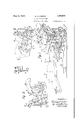
- Figure 1 is a cross-sectional, view of a portable-typewriter,- showing only such parts as are necessary to illustrate the invention.
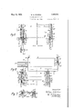
- Figure 2 is afragmentary sectional view, looking from thecenter toward the right side part of the shiftable carriageframe.
- Figure '3' is a fragmentarysectional View, looking from the center toward the left side of the typewriter, and showing one of the plates from which the shiftable carriage-' frame is swung.
- Figure 4 is a detail plan view of one of the means for adjusting the carriage-frame.
- F igure 5 is a section'al plan viewindicated byline 5'-'5 in Figures 1 and j
- Figure 6 is-a sectional front view indicated by line 6+6 in Figures 1 and 3.
- Figure 7 is a detail sectional plan view of the adjusting means for taking up the end thrust and end play of the carriage-frame. This view is indicated by line 7.7 of Figure6. i
- flO is a platen around which a work-sheet, not shown, may be fed.
- Said type-bar 11 islactuated by one of keys 13 by means'of suitable linkage, not shown.
- a platen-carriage 14 is actuated in aletter-feed movement by a spring-drum 14: an? escape'ment'mechanism and connections 1 V V
- Theplaten 10 is revolubly mounted in the carriage 14, which consists of an inner bar 15 and end plates 16.
- Said end plates have inwardly-bent tabs 16 with elongated screwholes, and are adjustably fastened to, and solidly supported upon, said inner bar.
- the spindle 17 of the'platen has a fixed "bearing in the left end plate,'and an adjustable bearingfor the right end ofthe spindle.
- Said adjustablebearing which is a feature of this invention, is in the form'of a lever 18 pivoted at-19 against the inner side of the right end'plate Sensitive adjustment of said lever is obtained by means of a plate 20,
- Said plate 20 is" guided in' a forward and semen rearward direction by closely fitting projection's'21 from the-inner side of the end plate,
- Said bearings consist of a rear rail 29, a front rail 30 and rollers 31, upon which the carriage 14 rides.
- the rear rail 29 is shiftably mounted upon a ledge 32 of across-bar 33, thus providing means for adjusting the space between the rails 29 and 30.
- the adjustment is secured by a suitable number of clamp screws 34, which pass through elongated holes in the ledge 32, and are threaded into the rear rail 29. Said screws 34 are easily accessible.”
- said platen carriage is mounted in'a shiftable carriageframe. consisting of end plates35 and'36; connected by means ofjthe carriage rail 30 and the cross-bar 33 and including an abutment 33 for the adjustable margin-stops] 33
- Said carriage-frame is swung upon'two upper arms 37, 38 and two lower arms 39, 40, one of each at each end ,of the ca'rriage frame.
- Said arms are arranged togive the platen a linear motion substantially parallel-to the face of the type whenprinting. Aswill be seen in the drawings, one end of each of said arms is pivoted to the carriage-frame, and the other ends are pivoted and fixed externally to the carriage-frame.
- the lower arms 39 and 40 are rigidly connected-by a crossbar 41. forming a frame whichis' pivotally supported by trunnion-screws 42 (see Figure 5), threaded into plates 43 and4'4, which also carry fixed pivots for the upper arms 37 and 38.
- Saidplates43 and 44 being adjustable in a direction perpendicular tothe face of the type when printing,constitute another feature of this invention.
- said plates 43 and 44 are guided by-the closelyfitting sides 45 of depressions machined in the typewriter side frames 46,47, andare easilyand sensitively'adjusted by means illustrated' in detail in Figure 4.
- Said means include a' plate 48'1'iveted to'each typewriter sideframe andha'ving a right-angle bend, slotted to engage a groove 49 in the head ofa n adjusting screw 50, which isthreaded'into tabs51, projecting from the carriage-frame. side plates 43-and 44.
- the type-bars are lim ited in their movement by hitting a stop-ring at 52 (see Figure For'this reason it is necessary to bring the printing line on the platen up to, and parallel to, the plane in which the faceof the type normally strikes;-
- the carriage-frame is pivoted to the lower arms SQ-and 40 upon studs-54 and 55 project-v ing fronrsaid'lower arm's.
- the notch 56 inthe right 's'ideof the carriage-frame engagesthe pivot stud 55, forming aclosedbearing thereon in conjunction with the hook-shaped extremity 57 of the member. 58.
- -*Said member 58 is adjustably clamped to'the'carriage-frame side plate'by a screw 59;-which passes through an inclined slot, 60 in thecarriage-frame side plate.
- the incli-v nation-of slot 60 to the sides of the notch 56 facilitatestheadjustment of the member 58 to 'thepivot55.
- a similar "bearing upon the pivot '54 is providedrfor the left-side of-the carriageframe (see Figure' l). .Instead, however, of the top of the notch bearing. upon the pivotthe edge of'a bar 61 is interposed and serves as one side ofthe bearing. Said bar is adjustable by means of a screw 62 threaded through a-block 63 projecting from the left side plate 35 of thecarriage-frame. The-ad'- justment is securedbymeans of a clampscrew64 passing throughan elongated hole 65 in the carriage-frame and threaded into the bar 61. The bar 61 is pivoted upon a stud 66 screwed into side frame 35.
- Shifting the bar 61 and the related hook-shaped member 58 displaces the bearing formed thereby, and has the effect of raising or lowering that side ofthe carriage-frame with respect to the pivot 54.
- the'carriage-rails are adjusted parallel to the base of the typewriter, sothat. said carriage-rails are not inclined to said base.
- a case-shift-key 71 and a lever 72 are provided on each side of the keyboard. Said levers 72 are fulcrumed on studs 72, so that depression of a key 71 causes an arm 76 to rise and engage the shiftable carriage-frame structure at the studs 54 or 55.
- the lower arms 39- are seen at Figure 3 to extend forward considerably beyond the pivots 54, and to rest upon adjustable stops which support the shift-frame and carriage in normal position.
- the upward movement is arrestedby engagement of the forward extensions with the upper adjustable stops 75.
- the forward lengthening of the arms 39 afiords a closer adjustment, so as to bring the capital letters into better alignment with LAO the lower-case letters on the work-sheet.
- the adjustable stops 75 are rendered accessible, since they are altogether in front of the shift-frame and clear thereof, and they 1 are easily adjusted.
- a typewriting machine the combination with a revoluble platen and a platencarriage consisting of end plates shiftably mounted upon a bar guided by rails, of means for relatively truing the platen for parallelism to said rails, said truing means ineluding a platen-adjusting lever at one end of the platen, a cam-slide upon said platencarriage for shifting said lever, means for,
- the means for shifting said end ing means including alever at one end of the platen-carriage, an adjacent cam-slide for adjusting said lever,- and a screw for securing said cam-slide for adjustment, the head of said screw projecting outside the platencarriage so that said caln-slide may be manipulated by said head when said screw is loosened.
- a typewriting machine the combination with a machine-frame, a revoluble plat-. en, type-bars of limited printing movement, and a platen-carriage mounted in a shiftable frame, of type-i1npression-controlling means consisting of shiftable members uponwhich said shiftable frame ismounted.
- said members being adjustably secured to the machineframe andv guided therein, and easily accessibleadjusting connections between said members and the machine-frame, whereby said members and consequently the shiftable frame and platen may be sensitively adjusted towardsand away from the printing point of the type-bars, and adjustable stops fixedupon each side of the machine-frame, independent- 1y of said shiftable members, to limit the upand-down throw of the shiftable frame.
- a typewriting machine the combination with a machine-frame, a revoluble platen, type-bars of limited printing movement, and a platen-carriage mounted in a shiftable frame, said shiftable frame being swingably mounted upon arms for case-shifting, of type-impression-controlling means consisting ofshiftable members upon which said arms are pivoted, said members being adjustably secured to the machine-frame and guided therein, and easily accessible adjusting screw connections between said members and the machine-frame, whereby said members and consequently the platen may be sensitively adjusted for type-impressions, and adjustable stops fixed upon each side of the machine-frame, independently of. said shiftable members, vto limit the up-and-down throw of the shiftable frame.
- type-bars means for limiting the printing strokes of the type-bars a platen, a platen-carriage, a shiftable-frame having rails guiding and. supporting said carriage, two upper side arms and two lower side arms whereon said shiftable frame is swung to move in a direction substantially parallel to the face of a type when printing, bracketplates at the sides of the machineframe, said lower arms hinged upon said bracket-plates, means whereby the upper arms are also pivoted upon said bracketplates, said machine-frame having means to guide said bracket-plates at about right angle to the printing position of the types, adjusting means for each bracket-plate, clamping screws passing through elongated holes in the typewriter-frame, and adjustable stops fixed upon each side of the machine-frame, independently of said bracket-plates, to'limit the up-and-down throw of the shiftable frame.
- type-bars means forlimiting the printing strokes of the type-bars, a platen, a platen-carriage, a shiftable frame having rails guiding and supporting said carriage, two upper side arms and two lower side arms whereon said shiftable frame is swung to move in a direction substantially parallel to the face of a type when printing, a cross-bar rigidly connecting the lower arms to form a swing-frame, bracket-plates at the sides of the machine-frame, said lower arms hinged upon said bracket-plates, means whereby the upper arms are also pivoted upon said bracket-plates, said machine-frame having means to guide said bracket-plates at about right angle to the printing position of the types, adjusting means for each bracket-plate, clamping screws passing through elongated holes in the typewriter-frame, and adjustable stops fixed upon each side of the machine-frame, independently of said bracket-plates, to limit the up-and-down throw of the shiftable frame.
- type-bars means for limiting the printing strokes of the type-bars, a platen, a platen-carriage, a shiftable frame having rails guiding and supporting said carriage, two upper side arms and two lower side arms whereon said shiftable frame is swung to move in a direction substantially parallel to the face of a type when printing, a cross-bar rigidly connecting the lower arms to form a swing-frame, bracket-plates at the sides of the machine-frame, said lower arms hinged upon said bracket-plates, means whereby the upper arms are also pivoted upon said bracket-plates, said machineframe having means to guide said bracketplates at about right angle to the printing position of the types, a plate riveted to each side of the typewriter-frame and having a part engaging a groove in a shift-frame adjusting screw mounted upon the machineframe and having an operating head projecting to position accessible from the rear of the machine, clamping screws passing through elongated holes in the typewriterframe, and, adjustable stops fixed upon each side of
Landscapes
- Common Mechanisms (AREA)
Description
, 1925 2. Sheets-Sheet 1 May 10, 1932. w. A. DOBSON TYPEWRITING MACHINE Filed Nov. 28
Patented May 10, 1932 UNITED; STAT-Es PAT N OFFICE WILLIAM A. DOBSON 0F BRIDGEPORT, CONNECTICUT; 'ASSIGNOR '1 mmnnwoon ELLIOTT FISHER COMPANY, 01 NEW YORK, N. Y.', .A CORPORATIQNOF DELAWARE lil rrrnwni'rine MACHINE Application nean vemuer as, 1925.. Serial No. 71,816. I V
This invention relates to typewriting machines, and particularly to means for adjust.- ing the Work platen audits supporting elements, so' that uniform impressions and alignment of the type'may be obtained along the whole printing line on said'platen'. Said means for adjustments are so designed that the necessary adjustmentsmaybe easily and positively made and secured "against disturbance. Easy accessibility and sensitiyene'ssof the adjusting means are other features o f this invention.
The invention and described and illustrated, are applied to a portable style typewriting machine having a shiftable platen operatively" connected to parallel to tl1e"carriage-rails,so it is provided case-shift keys. Q
The use of a typewriter as a portable machine renders its adjustments liable to displacement,and for this reason simple and easily'accessible means are provided' to e01? rect and maintain the adjustments herein described. j l j 1 The provisions 7 of this invention include means for adjusting theplaten parallel to the carriage-rails, means-for adjusting the car riage-rails for a running fit of the carriage thereon, means for-adjusting the shiftable carriage-frame, with the rails parallel to the typewriter base and also. in suchmanner'. as to control the type-impressions along the whole length of the platen; and means for taking up the end thrust and end playofthe carriage-fram'e I l The platen-axle; adjustment is e'fiected by meansof a lever'mounte'd on the side of'the platen-frameat one end of the platen. v The two carriage-rails are of the construe tion usual in typewriters Upon them issup ported a carriage having end plates between which the platen is revolubly mounted; said l'atesconnected by a grooved roller-bearing bar which comets with said rails to guide the ci riage. 1 f The bearing forone end of the platenis its features, as hereinfixed in one of the end plates, and the platen is adjusted forparallelism to the'carriagerails by means of a lever on theinner side of.
the other end plate. Said lever has a'beara 'ing hole forthe platenandis actuated by a cam sli de, which is secured after adjustment by means ofa clamp-screw. The head "of said screwprojects through the end plate and is v easily accessible. When said screw is loosened thecam-slide may be easily manipulated thereby. Thecam-slide andlever are disposed to shift the bearing hole'in a direc tion parallel to the face of the type when printing. p V
This adjustment inon e directiononly does not suflice in all cases to bring the platen Theouter carriage-rails are adjusted to the inner bar, and the rollers by shifting one of said outer rails. When said outer .rail has been adjusted it is clampedto the ledge upon which it is supported by a suitable number of screws. The outer carriage-rails are a part of the shiftable carriage-frame structure, and, in order to bring said rails parallel to. the
base of the typewriter, the shiftable carriageframe 'mustbe properly adjusted upon its supporting frame,
' For adjustingthe shiftable carriage-frame parallel to the base ofthe' typewriter, one
side of said' shiftable carriage-frame is at ranged to be raised or lowered with respect to the lower frame whereon it is swung. Upon one of the studs projecting from said frame, the adjustable side of the shiftable car-' riage-frame is supported at its lower edge by means of a notch, the sides of which fit the stud, but the top of said notch is clear of said stud. An adjustable bar spans the notch, so that the lower edge of said bar rests upon the stud and forms a bearing thereon. Said bar is pivoted and clamped to the side of the shiftable carriage-frame, and as said bar is shifted up or down, the side of said shiftable carriage-frame is lowered or raised. The adjustment is facilitated by means of a screw mounted in the shiftable carriage-frame and whose end abuts against the upper edge 'of the .adjustable bar. An adjustable hook-- shaped memberclamped to the'side ofthe shiftable carriage-frame closes the open end of the notch and completes the bearingaround the stud. The other side of the shiftable carriage-frame is similarly supported, but
there is no, adjustment, the top of the notch resting directly upon the stud.
Each side of the shiftable carriage-frame is swung upon two armspivoted to an adjusta-ble plate mounted o'nthe inner sideof thetypewriter-frame. A suitable adjusting screw connection betweenthe typewriter side frame and the adjustable plate ,is provided at each side, and the plate itself is guided'in a} direction perpendicular to the printing line onthe platen. By this means the jshiftable V carriage-frame is adjusted, so that the entire able carriage-frame.
printing line. on the platen coincides with the normal printing point of the type-bars; thus securing uniform impressions of the type along said line.. ,It will be understood that the printingmovement of the type-bars is limited'by the usual stop. This adjustment is secured by screws which clamp the adj ustable plates to the typewriter side frames, 7
The shiftable carriage-frame is guidedin its case-shift movements, between the'heads of screws placed opposite each other and mounted in hubs which are a part of the ad'- justable plates previously mentioned. Of said screws, the leftjone is adjustable, so that the space in which the shiftable carriageframe is constrained to more may be closely regulated and-thereby insure even spacing of the letters by eliminating end play. The heads of these screws also take up the end -ln'usts of the shiftable carriage-frame, it being understood that the letterfeed mechanism and margin-stops are mounted on the shift-' of the typewriter, and showing herein described, which form a complete combination by means of which extreme flexibility of adjustment of the platen and its supportingelements is attained.
It will be understood, however, that one or more of said adjusting means may, to advantage, be used alone, the others being omitted, and that such separate and independent use of one or more of said adjusting means is within the scope of this invention.
' Other features and advantages will hereinafter appear. In the accompanying drawings,
Figure 1 isa cross-sectional, view of a portable-typewriter,- showing only such parts as are necessary to illustrate the invention.
In this'view the carriage itself is partly crosssectioned.
Figure 2 is afragmentary sectional view, looking from thecenter toward the right side part of the shiftable carriageframe.
Figure '3'is a fragmentarysectional View, looking from the center toward the left side of the typewriter, and showing one of the plates from which the shiftable carriage-' frame is swung.
"Figure 4 is a detail plan view of one of the means for adjusting the carriage-frame.
F igure 5 is a section'al plan viewindicated byline 5'-'5 in Figures 1 and j Figure 6 is-a sectional front view indicated by line 6+6 in Figures 1 and 3. i
Figure 7 is a detail sectional plan view of the adjusting means for taking up the end thrust and end play of the carriage-frame. This view is indicated by line 7.7 of Figure6. i
In the typewriter to which this invention is appliedflO is a platen around which a work-sheet, not shown, may be fed. A typebar 11, swungabout a' fulcrum 12, prints through a ribbon, not shown, uponsaid worksheet. Said type-bar 11 islactuated by one of keys 13 by means'of suitable linkage, not shown. 7 A platen-carriage 14 is actuated in aletter-feed movement by a spring-drum 14: an? escape'ment'mechanism and connections 1 V V Theplaten 10 is revolubly mounted in the carriage 14, which consists of an inner bar 15 and end plates 16. Said end plates have inwardly-bent tabs 16 with elongated screwholes, and are adjustably fastened to, and solidly supported upon, said inner bar. The spindle 17 of the'platen has a fixed "bearing in the left end plate,'and an adjustable bearingfor the right end ofthe spindle. Said adjustablebearing, which is a feature of this invention, is in the form'of a lever 18 pivoted at-19 against the inner side of the right end'plate Sensitive adjustment of said lever is obtained by means of a plate 20,
slidably mounted adjacent said lever 18.
Said plate 20 is" guided in' a forward and semen rearward direction by closely fitting projection's'21 from the-inner side of the end plate,
and the slot 22 in the end plate, through which passes the easily accessible clam screw 23. A close fitting slot 24 engages the" stantially parallel to the face of the type when it prints. The hole 27 in the right end plate is enlarged to clear the spindle 17. By means of this adjustment, which is secured by the clamp-screw 23, and theshiftable position of the end plates upon the inner bar'15, the
platen may be adjusted parallel to the carriage-rails. This adjustment compensates for any irregularity inthe end plates, duethe manufacturing tolerances. v 7
Another feature of this invention 'isthe easily accessible 'means for taking up play between the carriage and its bearings. Said bearings consist of a rear rail 29, a front rail 30 and rollers 31, upon which the carriage 14 rides. The rear rail 29 is shiftably mounted upon a ledge 32 of across-bar 33, thus providing means for adjusting the space between the rails 29 and 30. The adjustment is secured by a suitable number of clamp screws 34, which pass through elongated holes in the ledge 32, and are threaded into the rear rail 29. Said screws 34 are easily accessible."
For shifting the platen-carriage 14 from lower-case to upper-case position, said platen carriage is mounted in'a shiftable carriageframe. consisting of end plates35 and'36; connected by means ofjthe carriage rail 30 and the cross-bar 33 and including an abutment 33 for the adjustable margin-stops] 33 Said carriage-frame is swung upon'two upper arms 37, 38 and two lower arms 39, 40, one of each at each end ,of the ca'rriage frame. Said arms are arranged togive the platen a linear motion substantially parallel-to the face of the type whenprinting. Aswill be seen in the drawings, one end of each of said arms is pivoted to the carriage-frame, and the other ends are pivoted and fixed externally to the carriage-frame. The lower arms 39 and 40 are rigidly connected-by a crossbar 41. forming a frame whichis' pivotally supported by trunnion-screws 42 (see Figure 5), threaded into plates 43 and4'4, which also carry fixed pivots for the upper arms 37 and 38. Saidplates43 and 44, being adjustable in a direction perpendicular tothe face of the type when printing,constitute another feature of this invention. For this purpose, said plates 43 and 44 are guided by-the closelyfitting sides 45 of depressions machined in the typewriter side frames 46,47, andare easilyand sensitively'adjusted by means illustrated' in detail in Figure 4. Said means include a' plate 48'1'iveted to'each typewriter sideframe andha'ving a right-angle bend, slotted to engage a groove 49 in the head ofa n adjusting screw 50, which isthreaded'into tabs51, projecting from the carriage-frame. side plates 43-and 44. The type-bars are lim ited in their movement by hitting a stop-ring at 52 (see Figure For'this reason it is necessary to bring the printing line on the platen up to, and parallel to, the plane in which the faceof the type normally strikes;-
By means of the last adjustment described, this is easily done, the adjusting screws 5O being readily accessible, and this adjustment is'secured by: clamp-screws 53, which pass through elongated holes 28 in the typewriter side frames.
' The carriage-frame is pivoted to the lower arms SQ-and 40 upon studs-54 and 55 project-v ing fronrsaid'lower arm's. The notch 56 inthe right 's'ideof the carriage-frame (see Figure 2) engagesthe pivot stud 55, forming aclosedbearing thereon in conjunction with the hook-shaped extremity 57 of the member. 58. -*Said member 58 is adjustably clamped to'the'carriage-frame side plate'by a screw 59;-which passes through an inclined slot, 60 in thecarriage-frame side plate. The incli-v nation-of slot 60 to the sides of the notch 56 facilitatestheadjustment of the member 58 to 'thepivot55. v r
A similar "bearing upon the pivot '54 is providedrfor the left-side of-the carriageframe (see Figure' l). .Instead, however, of the top of the notch bearing. upon the pivotthe edge of'a bar 61 is interposed and serves as one side ofthe bearing. Said bar is adjustable by means of a screw 62 threaded through a-block 63 projecting from the left side plate 35 of thecarriage-frame. The-ad'- justment is securedbymeans of a clampscrew64 passing throughan elongated hole 65 in the carriage-frame and threaded into the bar 61. The bar 61 is pivoted upon a stud 66 screwed into side frame 35. Shifting the bar 61 and the related hook-shaped member 58 displaces the bearing formed thereby, and has the effect of raising or lowering that side ofthe carriage-frame with respect to the pivot 54. By this means the'carriage-rails are adjusted parallel to the base of the typewriter, sothat. said carriage-rails are not inclined to said base.
- -.Another feature of this-invention is illustrated in detail in Figure 7 and is the adjustable abutting screw 67. .The reactions of the jolting impulses, due to the letter-feeding movement ofthe carriage, are taken up by the head of-this screw, thus avoiding strain of the carriage-frame. The adjustment is secured by. a lock-nut 68, for which a clearancehole 68 inthe side frame 46 is pro.- vided. Said screw 67 is threaded into a hub (i9 ofv the plate 43. Similarly on the right side the carriage-frame is retained and guided by theheadof a screw 70, which need not be adjustable. The screws 67 and 70 also take up-the reactionswdue to margini.
stopping, particularly screw 7 O, which takes upthe-sharpreaction when the carriage is returned against the right margin-stop. The adjustment ofthe screw 67 also takes up end play of the carriage-frame, thus insuring evenspacing of-the typing. The hubs 69 also serve as fixed pivots for the upper arms 37 and 38, said arms being retained by the heads of the screws 67 and 70. For manually shifting the-platen, a case-shift-key 71 and a lever 72 are provided on each side of the keyboard. Said levers 72 are fulcrumed on studs 72, so that depression of a key 71 causes an arm 76 to rise and engage the shiftable carriage-frame structure at the studs 54 or 55. The case-shift levers are retracted by springs 7 3 until stopped by projections 74 from the sides of said levers striking the edge of an opening in the side frame.- The upward and downward movements of the: carriage-shift-frame are limited by adjustable screw-stops 75 threaded into .suitable bosses in the right and left side frames; As will be seen in the drawings, said screw-stops limit the movement of the lower arms 39 and 40, and consequently the movementof the carriage-frame. The screw-stops are secured by lock-nuts 76 and it Will be noted that they are easily accessible.
The lower arms 39- are seen at Figure 3 to extend forward considerably beyond the pivots 54, and to rest upon adjustable stops which support the shift-frame and carriage in normal position. The upward movement is arrestedby engagement of the forward extensions with the upper adjustable stops 75. The forward lengthening of the arms 39 afiords a closer adjustment, so as to bring the capital letters into better alignment with LAO the lower-case letters on the work-sheet. At thesame time clearance is afforded, and the adjustable stops 75 are rendered accessible, since they are altogether in front of the shift-frame and clear thereof, and they 1 are easily adjusted.
Variations may be resorted to Within the scope of the invention, and portions of the improvements may be used without others.
"Having thus described my invention, I claim: I 1
1. In a typewriting machine, the combination with a revoluble platen, a platen-carriage, and rails for guiding said carriage'in its letter-feed movement, of adjustable means for relatively truing said platen for parallelism to said rails, said means including adj ustable devices for shifting and securing the bearing of one end of the platen, the other end of said platen being in a fixed bearing. 2. In a typewriting machine, the combination with a revoluble platen and a platencarriage consisting of end plates shiftably mounted upon a bar guided by rails, of means for relatively truing the platen for parallelism to said rails, said truing means ineluding a platen-adjusting lever at one end of the platen, a cam-slide upon said platencarriage for shifting said lever, means for,
securing the cam-slide after adjustment, and means for shifting and securing one or both end plates, the means for shifting said end ing means including alever at one end of the platen-carriage, an adjacent cam-slide for adjusting said lever,- and a screw for securing said cam-slide for adjustment, the head of said screw projecting outside the platencarriage so that said caln-slide may be manipulated by said head when said screw is loosened.
4. In a typewriting machine, the combination with a machine-frame, a revoluble plat-. en, type-bars of limited printing movement, and a platen-carriage mounted in a shiftable frame, of type-i1npression-controlling means consisting of shiftable members uponwhich said shiftable frame ismounted. said members being adjustably secured to the machineframe andv guided therein, and easily accessibleadjusting connections between said members and the machine-frame, whereby said members and consequently the shiftable frame and platen may be sensitively adjusted towardsand away from the printing point of the type-bars, and adjustable stops fixedupon each side of the machine-frame, independent- 1y of said shiftable members, to limit the upand-down throw of the shiftable frame.
5. In .a typewriting machine, the combination with a machine-frame, a revoluble platen, type-bars of limited printing movement, and a platen-carriage mounted in a shiftable frame, said shiftable frame being swingably mounted upon arms for case-shifting, of type-impression-controlling means consisting ofshiftable members upon which said arms are pivoted, said members being adjustably secured to the machine-frame and guided therein, and easily accessible adjusting screw connections between said members and the machine-frame, whereby said members and consequently the platen may be sensitively adjusted for type-impressions, and adjustable stops fixed upon each side of the machine-frame, independently of. said shiftable members, vto limit the up-and-down throw of the shiftable frame.
6, The combination of type-bars, means for limiting the printing strokes of the type-bars a platen, a platen-carriage, a shiftable-frame having rails guiding and. supporting said carriage, two upper side arms and two lower side arms whereon said shiftable frame is swung to move in a direction substantially parallel to the face of a type when printing, bracketplates at the sides of the machineframe, said lower arms hinged upon said bracket-plates, means whereby the upper arms are also pivoted upon said bracketplates, said machine-frame having means to guide said bracket-plates at about right angle to the printing position of the types, adjusting means for each bracket-plate, clamping screws passing through elongated holes in the typewriter-frame, and adjustable stops fixed upon each side of the machine-frame, independently of said bracket-plates, to'limit the up-and-down throw of the shiftable frame.
7. The combination of type-bars, means forlimiting the printing strokes of the type-bars, a platen, a platen-carriage, a shiftable frame having rails guiding and supporting said carriage, two upper side arms and two lower side arms whereon said shiftable frame is swung to move in a direction substantially parallel to the face of a type when printing, a cross-bar rigidly connecting the lower arms to form a swing-frame, bracket-plates at the sides of the machine-frame, said lower arms hinged upon said bracket-plates, means whereby the upper arms are also pivoted upon said bracket-plates, said machine-frame having means to guide said bracket-plates at about right angle to the printing position of the types, adjusting means for each bracket-plate, clamping screws passing through elongated holes in the typewriter-frame, and adjustable stops fixed upon each side of the machine-frame, independently of said bracket-plates, to limit the up-and-down throw of the shiftable frame.
8. The combination of type-bars, means for limiting the printing strokes of the type-bars, a platen, a platen-carriage, a shiftable frame having rails guiding and supporting said carriage, two upper side arms and two lower side arms whereon said shiftable frame is swung to move in a direction substantially parallel to the face of a type when printing, a cross-bar rigidly connecting the lower arms to form a swing-frame, bracket-plates at the sides of the machine-frame, said lower arms hinged upon said bracket-plates, means whereby the upper arms are also pivoted upon said bracket-plates, said machineframe having means to guide said bracketplates at about right angle to the printing position of the types, a plate riveted to each side of the typewriter-frame and having a part engaging a groove in a shift-frame adjusting screw mounted upon the machineframe and having an operating head projecting to position accessible from the rear of the machine, clamping screws passing through elongated holes in the typewriterframe, and, adjustable stops fixed upon each side of the machine-frame,independently of and limiting its throw.
WILLIAM A. DOBSON.
Priority Applications (1)
| Application Number | Priority Date | Filing Date | Title |
|---|---|---|---|
| US71876A US1858041A (en) | 1925-11-28 | 1925-11-28 | Typewriting machine |
Applications Claiming Priority (1)
| Application Number | Priority Date | Filing Date | Title |
|---|---|---|---|
| US71876A US1858041A (en) | 1925-11-28 | 1925-11-28 | Typewriting machine |
Publications (1)
| Publication Number | Publication Date |
|---|---|
| US1858041A true US1858041A (en) | 1932-05-10 |
Family
ID=22104159
Family Applications (1)
| Application Number | Title | Priority Date | Filing Date |
|---|---|---|---|
| US71876A Expired - Lifetime US1858041A (en) | 1925-11-28 | 1925-11-28 | Typewriting machine |
Country Status (1)
| Country | Link |
|---|---|
| US (1) | US1858041A (en) |
-
1925
- 1925-11-28 US US71876A patent/US1858041A/en not_active Expired - Lifetime
Similar Documents
| Publication | Publication Date | Title |
|---|---|---|
| US1858041A (en) | Typewriting machine | |
| US2178682A (en) | Typewriting machine | |
| US1655425A (en) | Typewriting machine | |
| US1082536A (en) | Type-writing machine. | |
| US1245220A (en) | Type-writing machine. | |
| US1787574A (en) | Carriage-shift mechanism for typewriting machines | |
| US1737723A (en) | Typewriting machine | |
| US2142246A (en) | Typewriting machine | |
| US1242244A (en) | Type-writing machine. | |
| US1164945A (en) | Type-writing machine. | |
| US754242A (en) | Type-writing machine. | |
| US1478235A (en) | Typewriting machine | |
| US1248346A (en) | Type-writing machine. | |
| US940395A (en) | Tabulating device for type-writers. | |
| US727216A (en) | Type-writing machine. | |
| US1181675A (en) | Type-writing machine. | |
| US833283A (en) | Type-writer construction. | |
| US1317482A (en) | Type-writing machine | |
| US1569052A (en) | Typewriting machine | |
| US952749A (en) | Type-writing machine. | |
| US1165941A (en) | Ribbon mechanism for type-writing machines. | |
| US1767278A (en) | Typewriting machine | |
| US713434A (en) | Type-writing machine. | |
| US1481793A (en) | Typewriting machine | |
| US1395503A (en) | Typewriting-machine |