US1858033A - Trimming machine - Google Patents
Trimming machine Download PDFInfo
- Publication number
- US1858033A US1858033A US414426A US41442629A US1858033A US 1858033 A US1858033 A US 1858033A US 414426 A US414426 A US 414426A US 41442629 A US41442629 A US 41442629A US 1858033 A US1858033 A US 1858033A
- Authority
- US
- United States
- Prior art keywords
- knife
- pedal
- book
- bar
- clamp
- Prior art date
- Legal status (The legal status is an assumption and is not a legal conclusion. Google has not performed a legal analysis and makes no representation as to the accuracy of the status listed.)
- Expired - Lifetime
Links
- 238000009966 trimming Methods 0.000 title description 25
- 210000005069 ears Anatomy 0.000 description 4
- 230000000994 depressogenic effect Effects 0.000 description 3
- 230000000694 effects Effects 0.000 description 2
- 230000035939 shock Effects 0.000 description 2
- 230000006835 compression Effects 0.000 description 1
- 238000007906 compression Methods 0.000 description 1
- 238000010276 construction Methods 0.000 description 1
- 239000012634 fragment Substances 0.000 description 1
- 238000000034 method Methods 0.000 description 1
- 238000009877 rendering Methods 0.000 description 1
- 230000000717 retained effect Effects 0.000 description 1
- 239000011435 rock Substances 0.000 description 1
- 125000006850 spacer group Chemical group 0.000 description 1
Images


Classifications
-
- B—PERFORMING OPERATIONS; TRANSPORTING
- B41—PRINTING; LINING MACHINES; TYPEWRITERS; STAMPS
- B41D—APPARATUS FOR THE MECHANICAL REPRODUCTION OF PRINTING SURFACES FOR STEREOTYPE PRINTING; SHAPING ELASTIC OR DEFORMABLE MATERIAL TO FORM PRINTING SURFACES
- B41D5/00—Working, treating, or handling stereotype plates
-
- Y—GENERAL TAGGING OF NEW TECHNOLOGICAL DEVELOPMENTS; GENERAL TAGGING OF CROSS-SECTIONAL TECHNOLOGIES SPANNING OVER SEVERAL SECTIONS OF THE IPC; TECHNICAL SUBJECTS COVERED BY FORMER USPC CROSS-REFERENCE ART COLLECTIONS [XRACs] AND DIGESTS
- Y10—TECHNICAL SUBJECTS COVERED BY FORMER USPC
- Y10T—TECHNICAL SUBJECTS COVERED BY FORMER US CLASSIFICATION
- Y10T83/00—Cutting
- Y10T83/566—Interrelated tool actuating means and means to actuate work immobilizer
- Y10T83/5669—Work clamp
- Y10T83/5715—With sequencing means
-
- Y—GENERAL TAGGING OF NEW TECHNOLOGICAL DEVELOPMENTS; GENERAL TAGGING OF CROSS-SECTIONAL TECHNOLOGIES SPANNING OVER SEVERAL SECTIONS OF THE IPC; TECHNICAL SUBJECTS COVERED BY FORMER USPC CROSS-REFERENCE ART COLLECTIONS [XRACs] AND DIGESTS
- Y10—TECHNICAL SUBJECTS COVERED BY FORMER USPC
- Y10T—TECHNICAL SUBJECTS COVERED BY FORMER US CLASSIFICATION
- Y10T83/00—Cutting
- Y10T83/566—Interrelated tool actuating means and means to actuate work immobilizer
- Y10T83/5669—Work clamp
- Y10T83/5787—Clamp driven by yieldable means
- Y10T83/5796—Drive means is resilient
-
- Y—GENERAL TAGGING OF NEW TECHNOLOGICAL DEVELOPMENTS; GENERAL TAGGING OF CROSS-SECTIONAL TECHNOLOGIES SPANNING OVER SEVERAL SECTIONS OF THE IPC; TECHNICAL SUBJECTS COVERED BY FORMER USPC CROSS-REFERENCE ART COLLECTIONS [XRACs] AND DIGESTS
- Y10—TECHNICAL SUBJECTS COVERED BY FORMER USPC
- Y10T—TECHNICAL SUBJECTS COVERED BY FORMER US CLASSIFICATION
- Y10T83/00—Cutting
- Y10T83/626—Operation of member controlled by means responsive to position of element remote from member [e.g., interlock]
- Y10T83/637—With means to initiate operation of member
-
- Y—GENERAL TAGGING OF NEW TECHNOLOGICAL DEVELOPMENTS; GENERAL TAGGING OF CROSS-SECTIONAL TECHNOLOGIES SPANNING OVER SEVERAL SECTIONS OF THE IPC; TECHNICAL SUBJECTS COVERED BY FORMER USPC CROSS-REFERENCE ART COLLECTIONS [XRACs] AND DIGESTS
- Y10—TECHNICAL SUBJECTS COVERED BY FORMER USPC
- Y10T—TECHNICAL SUBJECTS COVERED BY FORMER US CLASSIFICATION
- Y10T83/00—Cutting
- Y10T83/869—Means to drive or to guide tool
- Y10T83/8691—Unicyclic
-
- Y—GENERAL TAGGING OF NEW TECHNOLOGICAL DEVELOPMENTS; GENERAL TAGGING OF CROSS-SECTIONAL TECHNOLOGIES SPANNING OVER SEVERAL SECTIONS OF THE IPC; TECHNICAL SUBJECTS COVERED BY FORMER USPC CROSS-REFERENCE ART COLLECTIONS [XRACs] AND DIGESTS
- Y10—TECHNICAL SUBJECTS COVERED BY FORMER USPC
- Y10T—TECHNICAL SUBJECTS COVERED BY FORMER US CLASSIFICATION
- Y10T83/00—Cutting
- Y10T83/869—Means to drive or to guide tool
- Y10T83/887—Parallel draw-cut [e.g., translatory]
- Y10T83/8871—Link suspension
Definitions
- strips may be attached to a side edge of one or more leaves for attaching the leaves to a signature.
- a continuous strip employed for yattaching one trimmed signature to another in a series of books is severed between the books, and the ends of the strips project beyond the trimmed ends of the signatures and books.
- One of the. diculties involvedin trimming the ends of strips of the character described pertains to the adjustment of abook to the frame of a cutter so that the knife may pass across the end of the book in the proper path for trimming the end of the strip flush with the end of the book.
- a group of connected signatures may be trimmed closed or open, and a further object of the invention is to facilitate positioning of connected signatures in either closed or open condition for trimming the ends of signature-connecting strips.
- F 1g. l 1s a perspectlve view of a machine constructed in accordance withvour invention.
- Fig. 2 is a-front View partly in section of the machine.
- Fig. 3 is a side view of theV apparatus, parts of post flanges and wallsbeing broken away to better illustrate construction.
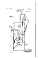
- Fig. 4 is a transverse section of operating mechanism on the line 4 4, Fig. 5.
- Fig. 5 is a section from front to back of operating mechanism on the line 5 5, Fig. 4. j
- Fig. 7 is a perspective view of the clutch members in disassembled position.
- Fig. 8 is an enlarged detail fragmentary section of a book guide, illustrating. means for adjustably supporting a knife-engaging wooden block.
- Fig. 9 is a fragmentary cross section showing a guide plate mounted with its front face in the plane of the front face of the knife.
- l designates a supporting frame including legs 2 and front and back walls 3 and 4 spaced from the floor to form a housing.
- the legs are angle members, one iiange of each merging with one of the walls 3 and 4, and other flanges such as 5 projecting laterally across the ends of the frame to a limited extent to leave the ends of the housing y open.
- Inwardly extending horizontal flanges 6 on thevupper ends of the walls form ledges or seats to -receive inwardly projecting hori- Zontal flanges 7 at the lower ends of walls p. trimming the stri ps'therein.
- the vertical edges of the plate 13 are connected with the edges of the plate 10 by side walls 14 to form an upper housing for purposes presently described of which the plates 10 and 13 are rear and front walls respectively.V y
- the lower housing is adapted to accommodate actuating mechanism and the upper housing forms a cover for book-retainin g and strip-cutting mechanism which will be particularly described.
- the case is adapted to be moved downwardly against a book adjusted on the table ⁇ as later described to'clamp the same/in posit-ion for
- the guides retain the clamp in a vertical path'spaced forwardly from the wall 1Y0 to permit a knife blade 19 to swing between the clamp andthe wall for trimming the projecting end ofthe strip.
- the clamp is actuated by a lever 2O having al yoke 21'on its front end pivotally mounted on a block 22 screwthreaded on the rod 15 whereby the. block be moved along the rod for varying the position of the path in which the clamp 'plate 16 moves, thus adapting the clamp to retain books of differentthicknesses.
- rlhe'rod may be rotated by a handle 23 for adjusting the position of the block 22 thereon.
- rlhe lever 20 projects forwardly through a vertically elongated slot 24 in the cover 12 and is pivotally mounted on ears Y25 of a rigid ⁇ bracket 26 fixed to the main support.
- a tubular'bar or sleeve 27 having its outer end pivoted tothe rear projecting end of the leveris operable by a pedal 28 through members present-ly described for moving the clamp downwardly toward the table.
- the pedal comprises a bar having a horizontally extending rear portion 29 pivoted to a depending ear-like bracket30iixed to the frame and-when depressed, the pedallopcrates downwardly on a bar 31 pivoted to the pedal at 32 and having an upper end pivotally connected to an arm 33keyed to a rock shaft 34 mounted in brackets 35 and 3 6 fixed to the rear wall 4.
- A.l spring '37 anchored to the upper edge Vflange, 6 of the front wall retracts the pedal and clamp.
- An arm 38 fixed to the shaft 34 projects oppositely from the arm 33, and a rod 39 pivoted to the arm 38 entends into the lower end ofthe tube 27 and is provided with a transverse pin 40 having opposite ends projecting outwardly through slots 41 in the tube wherebythe rod 39has limited movement longitudinally in the tube.
- a coil spring '42 sleeved on the rod 39 having opposite ends anchored respectively ing sufcient resistance to tend to stop the rod whenthe plate 16 is in clamping relation with the book. Further depression of the pedal is permitted, however, after the book is .,Clamped, and the pedal is adapted to effect operation of knife-actuating means when depressed beyond book-clamping position as presently described.
- the knife blade 19 comprises a relatively broad and long member having a cutting edge 44 extending vertically in rest position adjacent the clamp and is adapted to swing in an arcuate path back of the clamp transversely of the machine in a slot 45 in the table top 9 as indicated in Fig. 1.
- the blade is fixed to the advancing edge Vportions of a backing member 46.
- the backing member is supported and retained in the desired path of travel by links 47 and 48 having front ends pivotally connected respectively at 49 and 50 in a groove 51 formed in the rear edge of the backing member and rear ends pivoted on bolts 53 and '54 attached respectively to thevwall 10 and the rear wall 4 of the supporting frame.
- a depending ear 55 on the backing member 46 has a pivot pin 56 on which is mounted reciprocating rod or pitman 57 having its lower end pivoted by a pin 53 in the end of a crank 59 keyed to a shaft 6() mounted inl the lower housing as presently described.
- the rod 57 is adjustable as to length for 1 varying the path in which the knife swings.
- Fixed to the rear wall 4 of the lower housing adjacentV opposite side edges thereof are lugs 61 and 62 supporting a frame including side walls 63. and 64 parallel with the wall 4 and anintegral bottom 6.5.
- Bearings 68 and 69 in the sides 63 and 64 of the frame rotatably support the shaft 60.
- Bearings 70 in the sides support a shaft 7 2 in the same horizontal plane as the shaft 69, and spaced laterally therefrom as shown in Fig. 2.
- the shaft 72 is constantly rotated during use of the machine by a belt 73 running on a pulley 74 on the shaft 72 and operated by a motor 75 mounted on a plate 7 6 slidable on a shelf 77 attached to the bottom plate 65 of the frame.
- the motor plate is moved by a screw 7 8 for shifting-the motor to loosen or tighten the belt.
- the lower end of the latch extends through a rslot in the bottom 65 of the frame and is pivotally mounted on a pin 96 in a horizontal bar 97 having one end pivoted to an ear 98 depending from the bottom 65.
- the opposite end of the bar 97 is pivoted to a bolt 99 extending slidably through the bottom 65 and a spring 100 bearing oppositely against the bottom and the head of the bolt cushions downward movement of the latch as later described.
- the bar 93 has an elongatedslot 101 for slidable movement on a pin 102 mounted on the frame plate 90.
- Rods 103 and 104 having outer ends guided in perforate ears of brackets 105 and 106 on the plate l90 and opposite ends xed respectively in a lateral lug 107 onthe bar 93 and in the latch 84 are urged by springs 108 and 109 respectively to return the bar 93 to position for receiving the influence of the bell crank and returning the latch 84 to normal vertical position.
- the latch 84 when shifted laterally by the bar 93 and then returned by the spring 108 is stopped by a pin 110. s
- the clutch member 81 fixed to the constantly rotated gear includes a ring-like sleeve portion 111 forming a recess in the member to receive a flange 112 projecting from one face of the clutch member 80 and the ilange 112'is provided with recesses 113 to receive rollers 114.
- the clutch member 79 is keyed to the shaft 60, and has a boss 115 projecting through the member 80, land having a periphery provided with fiat relatively low portions 116 and intermediate high points 117.
- rlhe rollers 114 located in the recesses 113 are moved radially outwardly thereof into clutching frictional engagement with the ring when the member 80 rotates to cause the high points 117 to engagethe rollers, and bring about driving relation between the shaft 72 and thei shaft 60.
- a spring 118 having one end anchored to a screw 119 in the periphery of the member 79 and the other end anchored to a screw 120 in the outer'face of the member 80 tends to move the member 80 relative to the member 79.
- the bar 93 is located adjacent the clutch members 79 and 80, and in the Vpath ofthe teeth 86 and 87 oreither of them,rwhereby the teeth encounter and bearV upwardlyv ⁇ - against the bar whenmembers are near the end of a rotation, and release the bar from the latch 84, to permit the spring 109 to return the latch to normal position.
- the latch notch 85 is thereforel relocated in toothreceiving position before the clutch members yhave completed a rotation, and stop the members to prevent repetition of the clutching and knife-actuating operation.
- Meansfor locating a book to be operated upon by the knife include a side guide 121 having a depending bolt 122 slidable in a slotv A screw 124 movable in Y 123 in the table.
- the bottom 125 of the guide is adapted to be inserted in a ⁇ recess 126 in the table for retaining thekguide in fixed position with the vertical face 127 thereof aligned with a side edge of an opening 128 in the upper housing wall 10 provided toreceive ends cut from strips.
- the guide 121 ing vertical edge flange 129, and a clamp 130 pivotally mounted on the flange by a stud 131 retains a wooden block 132 against the flange in the vertical plane of the knife edge to receive the same.
- An adjusting screw 133 in an ear 134 onV the edge of the flange bears against the clamp to vary the inclination of the block according to the inclination of the knife edge due to reduction of upper for lower portions in the sharpening process.
- the wooden blockthus forms a backing member to support strip ends and receive the slicing strip of the knife edge; when the guide 121 is suitably located.
- the guide may be withdrawn, when opened books are to be trimmed having portions eX- tending in the area normally occupied by the guide.
- the housing wall 10 is spaced from they has a rearwardly project-y ies ⁇ table and spacing table by spacer blocks 135.
- Ears 136 on-the blocks have openings 137 to receive bolts for attaching a guide plate 138 thereto'havingv a front face lying in the vertical plane of the front face of the knife to cooperate ,with the knife to form a rear guide to receive the end edges of opposite portions of an opened book.
- An opening 139 is formed in the table top into which the projecting ends of strips may extend whenv a group of signatures is being j oggled Lto justify the end edges thereof, and a chute 140 below the opening is adapted toconcuct away fragments of paper and the like falling from the signatures being prepared foimounting in the machine.
- the suitable guides are located and adjusted to promote accurate feeding of the signatures, and the lever yoke is adj usted on the threaded rod 15, according to the thickness of the signatures fed.
- the extent of travel of the clamping rod 15 is constant, and theclamp 16 must therefore start at a lower position 'in Vorder to reach clamping position when a relatively thin signature or group of signatures is located on the table below the clamp;
- the clutch member 79 remains momentarily unmoved due to the factthat it is keyed tothe shaft 60.
- the member 80 is impelled by the spring 118 to rotate, and shifts the rollers to the high points on the member '79, thereby setting up clutching relation between the gear-connected member 81 andthe l,member 9.
- Driving connection is thus set up between the constantly rotating shaft 72 and the shaft 60, and the crank 59 is rotated to operate the knife-swinging bar 57'.
- the edge of the knife moves in an arc across the edges of the signature and confers a. slicing operation on the projecting ends of the strips.
- the latching bar 8 may move slightly vertically due to pivotal mountingthereof onthe pivoted bar 97, to yield to the shock of receiving and stopping' the clutch, the shock beingabsorbed by the spring '100, as suggested in Fig. .4.
- Theknife-operating member 57 may be shortened or llengthenedrto assure engagement of the knife jedge with the block 132.
- the knife swings a constant distance across the table. Due toreduction of the knife when sharpened, the cutting edge thereof mav not reach the block.
- rlhe member 57 may be shortened, thus setting the knife closer to the block in starting or rest position, so that it will movefurther toward the block when operated. j
- Y 1 In a trimming machine, a support, a memberfor clamping a book to the support, a knife, knife actuating means including a normally idle shaft and a constantly rotating shaft, means including: a pedal for operating the clamping member, a bar pivoted to the pedal, and means including ⁇ said bar'automatically :rendered eective upon operation of the pedal for eectingdriving connection between the shafts.
- a support for retaining a book in position to be trimmed
- means including a pedal and a crank connected with theV pedal and the clamp for operating the clamp, a knife, knife operating means vincluding a constantly moving shaft and an intermittently movable shaft, and meansresponsive to movement of the pedal for effectingk driving connection between the shafts.
- a book trimming machine including a support, a clamp for retaining a book in positionto be trimmed, and means including a pedal and a crank'connected with the pedal and the clamp for operating the clamp, a knife, knife operating means including a constantly moving shaft and an intermittently movable shaft, means including a spring-pressed clutch member for effecting driving connection between the shafts, and means operated by the pedal for rendering said clutch member effective.
- a book trimming machine including a support, a .clamp for retaining a book in position to be trimmed, means including a pedal, a crank, and a link connecting the pedal with the crank for operating.
- the clamp, a knife, knife operating means including a constantly moving shaft and an intermittently movable shaft, said link comprising a tubular bar, a rod slidable in the bar', and a spring on the rod bearing against the end of the bar, and means responsive to :novement of the pedal for effecting driving connection between the shafts.
- a support, a clamp, clamp guiding means on the support, clamp operating means includng a rod fixed tothe clamp, a lever having a yoke adjustable on the rod forl changing the path through which the clamp moves, a pedal, and a link connecting the pedal to the crank, said link comprising a tubular barV oivoted to the lever, a rod pivoted to the pedal and' slidable in the bar, and a coil spring sleeved on the rod and bearing oppositely against the pedal and the bar, a knife, knife operating means including normally lisengaged clutch members, said spring being; adapted to operate the clamp upon limited depression of the pedal, continued depression of the pedal tending ⁇ to compress the spring, and means effective upon compression 'if the spring for effecting driving connection between said clutch members.
- a machine of the character described for trimming strip ends from a book including a table, book-clamping means and cutting means including a knife.
- a guide supported by the table having a book-receiving face located' in the plane of the book-receiving face of the knife for cooperation with the knife for effecting location of the book for applying the knife to the strip.
- a book trimming machine including a support, a knife having a vertically extending cutting edge movable transversely of the support.
- knife supporting means including a pair of arms pivoted to the support, and means including an operating rod for moving the knife. said rod being adjustable to verv the path in which the knife moves.
- a trimming machine including a support. a knife having a, vertically extending cutting edge, and means for moving the knife including means for retaining the edge of the knife in vertical position, means including a block and a bracket supporting the block for receiving the edge of the knife at the outward limit of its travel, and means for adjusting the block to variations in the inclination of the edge of the knife.
- a trimming machine including a support having a slot, and a knife movable in the slot, a guide on the support above said slot having a book-receiving outer face aligned with the book-receiving outer face of the knife.
- a trimming machine including a support, a knife having a vertically extending cutting edge movable transversely of the support and an outer face forming a book l guide, a bracket on the support spaced 'transversely of the support from the path of the knife edge, and a guide plate removably ymounted on the bracket with the outer face of the plate in the plane of the outer face of the knife.
- a support having a slot
- ya knife having a vertically extending cutting edge movable in theV vincluding a table to support a book
- a knife having a vertically extending cutting edge having pivotal mounting on the frame to swing in an arcuate path adjacent one edge of the table
- a block movably mounted on the table in the path of the knife to receive the edge of the knife, and means for fixing the block in knife-receiving position.
Landscapes
- Engineering & Computer Science (AREA)
- Manufacturing & Machinery (AREA)
- Mechanical Engineering (AREA)
- Perforating, Stamping-Out Or Severing By Means Other Than Cutting (AREA)
Description
May 10, 1932- F. M. BRAcKr-:TT ET AL 1,858,033
May 10, 1932 F. M. BRACKETT ET AL 1,858,033
TRIMMING MACHINE Filed Dec. 1e, 1929 4 sheets-sheet 2l May 10, 1932' F. M. BRACKETT ET AL 1,858,033
TRIMMING MACHINE Filed Dec. 16, 1929 4 Sheets-Sheet 5 A TTORNEY May 10, 1932- F; M. BRACKTT ET AL 1,858,033
TRIMMING MACHINE 4 Sheets-Sheet 4 Filed Dec. 16, 1929 /N VENTO fred /Pl ffa/rz e0 /4// /a/MS.
.4 /TORNEY Patented May 10, 1932 UNITED STATES FRED lVI. BRACKETT AND LEO C. VTILLIAMS, OF TOPEKA, KASASASSIGNORS TO THE A vPATENT OFFICE BRACKETT STRIPPIN G MACHINE CO., OF TOPEKA, KANSAS, A COPARINERSHIP CON l SISTING OF EDWARD BRACKET'I AND FRED M. BRACKETT TRIMMING MACHINE Our invention relates to trimming machines and has for its principal object to trim the ends ofstr-ips projecting from upper or lower edges of signatures and the like.
In making magazines, pamphlets, books and the like, strips may be attached to a side edge of one or more leaves for attaching the leaves to a signature. A continuous strip employed for yattaching one trimmed signature to another in a series of books is severed between the books, and the ends of the strips project beyond the trimmed ends of the signatures and books. j Y
It is a difficult matter to trim ofi the ends of the strips flush with the ends-of the books and frequently the strips are left incompletely trimmed and form unsightly projections in the finished books. Y
Further objects of our invention are to facilitate the trimming of strip ends of the character described, to assure trimming the strip ends flush with the trimmed endsV of the books and to hold the books firmly in suitable position to receive the operation of the trimming mechanism.
One of the. diculties involvedin trimming the ends of strips of the character described, pertains to the adjustment of abook to the frame of a cutter so that the knife may pass across the end of the book in the proper path for trimming the end of the strip flush with the end of the book.
Further objects of our invention therefore are to facilitate adjustment of a book in a cutting frame to receive the'operation of a trimming knife, to automatically eifectthe operation of a knife when the book has been clamped in receiving position, and to assure proper operation of the several clamping and cutting elements for eifecting the cut.
A group of connected signatures may be trimmed closed or open, and a further object of the invention is to facilitate positioning of connected signatures in either closed or open condition for trimming the ends of signature-connecting strips. A v Y In accomplishing these and other objects of our invention, we have provided improved details of structure, the preferred forms of Awhich are illustrated in the accompanying drawings, wherein:
F 1g. l 1s a perspectlve view of a machine constructed in accordance withvour invention.
Fig. 2 is a-front View partly in section of the machine.
Fig. 3 is a side view of theV apparatus, parts of post flanges and wallsbeing broken away to better illustrate construction.
Fig. 4 is a transverse section of operating mechanism on the line 4 4, Fig. 5.
Fig. 5 is a section from front to back of operating mechanism on the line 5 5, Fig. 4. j
Fig. 6 Yis a fragmentary section on the line cwc, Fig. 5. y
Fig. 7 is a perspective view of the clutch members in disassembled position.
Fig. 8 is an enlarged detail fragmentary section of a book guide, illustrating. means for adjustably supporting a knife-engaging wooden block. Y
Fig. 9 is a fragmentary cross section showing a guide plate mounted with its front face in the plane of the front face of the knife. Referring in detail to the drawings: l designates a supporting frame including legs 2 and front and back walls 3 and 4 spaced from the floor to form a housing.
The legs are angle members, one iiange of each merging with one of the walls 3 and 4, and other flanges such as 5 projecting laterally across the ends of the frame to a limited extent to leave the ends of the housing y open.
Inwardly extending horizontal flanges 6 on thevupper ends of the walls form ledges or seats to -receive inwardly projecting hori- Zontal flanges 7 at the lower ends of walls p. trimming the stri ps'therein.
The vertical edges of the plate 13 are connected with the edges of the plate 10 by side walls 14 to form an upper housing for purposes presently described of which the plates 10 and 13 are rear and front walls respectively.V y
The lower housing is adapted to accommodate actuating mechanism and the upper housing forms a cover for book-retainin g and strip-cutting mechanism which will be particularly described.
Slidable in an opening in the cover 12 is a rod 15 fixed to a book-retaining clamp plate 16 mounted on the lower end of a rectangular case 17 slidably guided` between the front wall 13 and side guides 18 fixed to said wall.
The caseis adapted to be moved downwardly against a book adjusted on the table` as later described to'clamp the same/in posit-ion for The guides retain the clamp in a vertical path'spaced forwardly from the wall 1Y0 to permit a knife blade 19 to swing between the clamp andthe wall for trimming the projecting end ofthe strip.
The clamp is actuated by a lever 2O having al yoke 21'on its front end pivotally mounted on a block 22 screwthreaded on the rod 15 whereby the. block be moved along the rod for varying the position of the path in which the clamp 'plate 16 moves, thus adapting the clamp to retain books of differentthicknesses. rlhe'rod may be rotated by a handle 23 for adjusting the position of the block 22 thereon.
rlhe lever 20 projects forwardly through a vertically elongated slot 24 in the cover 12 and is pivotally mounted on ears Y25 of a rigid `bracket 26 fixed to the main support. A tubular'bar or sleeve 27 having its outer end pivoted tothe rear projecting end of the leveris operable by a pedal 28 through members present-ly described for moving the clamp downwardly toward the table.
The pedal comprises a bar having a horizontally extending rear portion 29 pivoted to a depending ear-like bracket30iixed to the frame and-when depressed, the pedallopcrates downwardly on a bar 31 pivoted to the pedal at 32 and having an upper end pivotally connected to an arm 33keyed to a rock shaft 34 mounted in brackets 35 and 3 6 fixed to the rear wall 4. A.l spring '37 anchored to the upper edge Vflange, 6 of the front wallretracts the pedal and clamp.
An arm 38 fixed to the shaft 34 projects oppositely from the arm 33, and a rod 39 pivoted to the arm 38 entends into the lower end ofthe tube 27 and is provided with a transverse pin 40 having opposite ends projecting outwardly through slots 41 in the tube wherebythe rod 39has limited movement longitudinally in the tube.
A coil spring '42 sleeved on the rod 39 having opposite ends anchored respectively ing sufcient resistance to tend to stop the rod whenthe plate 16 is in clamping relation with the book. Further depression of the pedal is permitted, however, after the book is .,Clamped, and the pedal is adapted to effect operation of knife-actuating means when depressed beyond book-clamping position as presently described.
' The knife blade 19 comprises a relatively broad and long member having a cutting edge 44 extending vertically in rest position adjacent the clamp and is adapted to swing in an arcuate path back of the clamp transversely of the machine in a slot 45 in the table top 9 as indicated in Fig. 1. The blade is fixed to the advancing edge Vportions of a backing member 46.
The backing member is supported and retained in the desired path of travel by links 47 and 48 having front ends pivotally connected respectively at 49 and 50 in a groove 51 formed in the rear edge of the backing member and rear ends pivoted on bolts 53 and '54 attached respectively to thevwall 10 and the rear wall 4 of the supporting frame.
A depending ear 55 on the backing member 46 has a pivot pin 56 on which is mounted reciprocating rod or pitman 57 having its lower end pivoted by a pin 53 in the end of a crank 59 keyed to a shaft 6() mounted inl the lower housing as presently described.
The rod 57is adjustable as to length for 1 varying the path in which the knife swings. Fixed to the rear wall 4 of the lower housing adjacentV opposite side edges thereof are lugs 61 and 62 supporting a frame including side walls 63. and 64 parallel with the wall 4 and anintegral bottom 6.5.
The shaft 72 is constantly rotated during use of the machine by a belt 73 running on a pulley 74 on the shaft 72 and operated by a motor 75 mounted on a plate 7 6 slidable on a shelf 77 attached to the bottom plate 65 of the frame. The motor plate is moved by a screw 7 8 for shifting-the motor to loosen or tighten the belt.
Intermittent driving yconnection of the shaft 72 with the shaft 60 is effected by clutch members 7 9, 80 and 81, and a large gear 82 keyedto the clutch member V81 which is freely rotatable on the shaft 60. The gear is lOO the cutter actuating mechanism is controlled by a latching bar 84 provided with a -notch 85 in which teeth 86 and 87 of the clutchA members 79 and 80 are normally engaged, anda latch-releasing lever 88 mounted on a pin 89 xed to a plate 90 bolted to the plate The lever 88 comprises a bell crank having an arm projecting in the vertical path of a finger 91 on the pedal bar'31, which moves the bell crank to cause its other arm 92 to engage the outer end of a horizontally reciprocating latch releasing bar 93 slidable in a slot 94 in the upper end portion of the latch 84 and having a notch 95 in its lower edge engaging the latch. y
The lower end of the latch extends through a rslot in the bottom 65 of the frame and is pivotally mounted on a pin 96 in a horizontal bar 97 having one end pivoted to an ear 98 depending from the bottom 65.
The opposite end of the bar 97 is pivoted to a bolt 99 extending slidably through the bottom 65 and a spring 100 bearing oppositely against the bottom and the head of the bolt cushions downward movement of the latch as later described.
The bar 93 has an elongatedslot 101 for slidable movement on a pin 102 mounted on the frame plate 90. Rods 103 and 104 having outer ends guided in perforate ears of brackets 105 and 106 on the plate l90 and opposite ends xed respectively in a lateral lug 107 onthe bar 93 and in the latch 84 are urged by springs 108 and 109 respectively to return the bar 93 to position for receiving the influence of the bell crank and returning the latch 84 to normal vertical position.
The latch 84 when shifted laterally by the bar 93 and then returned by the spring 108 is stopped by a pin 110. s
The clutch member 81 fixed to the constantly rotated gear includes a ring-like sleeve portion 111 forming a recess in the member to receive a flange 112 projecting from one face of the clutch member 80 and the ilange 112'is provided with recesses 113 to receive rollers 114. The clutch member 79 is keyed to the shaft 60, and has a boss 115 projecting through the member 80, land having a periphery provided with fiat relatively low portions 116 and intermediate high points 117.
The inner face of the member 79 .outside of the boss slides over the outer face of the member 8 0, and thev teeth 86 and 87 of the two members are adapted to engage inV the notch of the latch coincidently torestrain the ,K
members.
A spring 118 having one end anchored to a screw 119 in the periphery of the member 79 and the other end anchored to a screw 120 in the outer'face of the member 80 tends to move the member 80 relative to the member 79.
Then the latch 84 is shifted by operation of the pedal, and the clutch members 79 and 80 are released, the' spring 118 anchored by A the member 79 due to the inertia thereof,
causes the member 80 to advance and shift' the rollers into clutchingV relation withthe gear-supported ring 111. Rotative motion is thus transmittedto the clutch member 79 and shaft 60, to rotate the crank and cause l the knife to swing across the table.
The bar 93 is located adjacent the clutch members 79 and 80, and in the Vpath ofthe teeth 86 and 87 oreither of them,rwhereby the teeth encounter and bearV upwardlyv`- against the bar whenmembers are near the end of a rotation, and release the bar from the latch 84, to permit the spring 109 to return the latch to normal position. The latch notch 85 is thereforel relocated in toothreceiving position before the clutch members yhave completed a rotation, and stop the members to prevent repetition of the clutching and knife-actuating operation.
Meansfor locating a book to be operated upon by the knife include a side guide 121 having a depending bolt 122 slidable in a slotv A screw 124 movable in Y 123 in the table. the bottom 125 of the guide is adapted to be inserted in a `recess 126 in the table for retaining thekguide in fixed position with the vertical face 127 thereof aligned with a side edge of an opening 128 in the upper housing wall 10 provided toreceive ends cut from strips. Y
The guide 121 ing vertical edge flange 129, and a clamp 130 pivotally mounted on the flange by a stud 131 retains a wooden block 132 against the flange in the vertical plane of the knife edge to receive the same. An adjusting screw 133 in an ear 134 onV the edge of the flange bears against the clamp to vary the inclination of the block according to the inclination of the knife edge due to reduction of upper for lower portions in the sharpening process.
The wooden blockthus forms a backing member to support strip ends and receive the slicing strip of the knife edge; when the guide 121 is suitably located.
The guide may be withdrawn, when opened books are to be trimmed having portions eX- tending in the area normally occupied by the guide.
The housing wall 10 is spaced from they has a rearwardly project-y ies `table and spacing table by spacer blocks 135. Ears 136 on-the blocks have openings 137 to receive bolts for attaching a guide plate 138 thereto'havingv a front face lying in the vertical plane of the front face of the knife to cooperate ,with the knife to form a rear guide to receive the end edges of opposite portions of an opened book.
In F ig. 1 the macnineis shown with the guide `plate Vremoved from the ears 135t0 permit the guide 121 to be moved over the blocks into operating position.
An opening 139 is formed in the table top into which the projecting ends of strips may extend whenv a group of signatures is being j oggled Lto justify the end edges thereof, and a chute 140 below the opening is adapted toconcuct away fragments of paper and the like falling from the signatures being prepared foimounting in the machine.
In using a machine constructed as described, the suitable guides are located and adjusted to promote accurate feeding of the signatures, and the lever yoke is adj usted on the threaded rod 15, according to the thickness of the signatures fed. The extent of travel of the clamping rod 15 is constant, and theclamp 16 must therefore start at a lower position 'in Vorder to reach clamping position when a relatively thin signature or group of signatures is located on the table below the clamp;
A signature having been placed in correct position on the table, the pedal is depressed, and the spring l2 bearing against the end of the tubular 'bar 27 effects depression of the clamping rod'15 and the clamp plate 16 to engage the signature and latch the same to the table.l
Further depression of the pedal causes the lug on the pedal bar to engage thebell crankl lever and effectlateral shifting of the bar 93 to shift the latch 8a and release the clutch members. f
The clutch member 79 remains momentarily unmoved due to the factthat it is keyed tothe shaft 60. The member 80 is impelled by the spring 118 to rotate, and shifts the rollers to the high points on the member '79, thereby setting up clutching relation between the gear-connected member 81 andthe l,member 9. Driving connection is thus set up between the constantly rotating shaft 72 and the shaft 60, and the crank 59 is rotated to operate the knife-swinging bar 57'.
The edge of the knife moves in an arc across the edges of the signature and confers a. slicing operation on the projecting ends of the strips.
Before a cycle of swinging of the knife is completed, one Vor other of the clutch members k79 and 80 has rotated sufficiently to bring its tooth intowiping engagement with` the bottom edge ofthe bar 93, the tooth acting asav cam to lift the bar onits pivot pin 102, and effectrdease ofthe latch v84 1 therefrom.
.The latch ,isvv returned ,by theV spring 1.09l to clutch-latching position intime to receive andstop the clutch ,membersand suspend swinging .operation yof the knife :until the clutch members are again released by another operation of the pedal. .The latching bar 8 may move slightly vertically due to pivotal mountingthereof onthe pivoted bar 97, to yield to the shock of receiving and stopping' the clutch, the shock beingabsorbed by the spring '100, as suggested in Fig. .4. 'l`hebar93'is returned by the spring 108,130 normal position, and incidentally bears against the Vbell crank' lever to return the same to position` for `operation by the lug on.
the pedal bar.
. Theknife-operating member 57 may be shortened or llengthenedrto assure engagement of the knife jedge with the block 132. The knife swings a constant distance across the table. Due toreduction of the knife when sharpened, the cutting edge thereof mav not reach the block. rlhe member 57 may be shortened, thus setting the knife closer to the block in starting or rest position, so that it will movefurther toward the block when operated. j
YAWhat we claim and desire to secure by Letters Patent is: n
2. In ay book trimming machine, a support, a clamp for retaining a book in position to be trimmed, means including a pedal and a crank connected with theV pedal and the clamp for operating the clamp, a knife, knife operating means vincluding a constantly moving shaft and an intermittently movable shaft, and meansresponsive to movement of the pedal for effectingk driving connection between the shafts.
3. In a book trimming machine including a support, a clamp for retaining a book in positionto be trimmed, and means including a pedal and a crank'connected with the pedal and the clamp for operating the clamp, a knife, knife operating means including a constantly moving shaft and an intermittently movable shaft, means including a spring-pressed clutch member for effecting driving connection between the shafts, and means operated by the pedal for rendering said clutch member effective.
4. In a book trimming machine including a support, a .clamp for retaining a book in position to be trimmed, means including a pedal, a crank, and a link connecting the pedal with the crank for operating. the clamp, a knife, knife operating means including a constantly moving shaft and an intermittently movable shaft, said link comprising a tubular bar, a rod slidable in the bar', and a spring on the rod bearing against the end of the bar, and means responsive to :novement of the pedal for effecting driving connection between the shafts. c
5. In a machine of the character described. a support, a clamp, clamp guiding means on the support, clamp operating means includng a rod fixed tothe clamp, a lever having a yoke adjustable on the rod forl changing the path through which the clamp moves, a pedal, and a link connecting the pedal to the crank, said link comprising a tubular barV oivoted to the lever, a rod pivoted to the pedal and' slidable in the bar, and a coil spring sleeved on the rod and bearing oppositely against the pedal and the bar, a knife, knife operating means including normally lisengaged clutch members, said spring being; adapted to operate the clamp upon limited depression of the pedal, continued depression of the pedal tending` to compress the spring, and means effective upon compression 'if the spring for effecting driving connection between said clutch members.
6. In a machine of the character described for trimming strip ends from a book, including a table, book-clamping means and cutting means including a knife. a guide supported by the table having a book-receiving face located' in the plane of the book-receiving face of the knife for cooperation with the knife for effecting location of the book for applying the knife to the strip.
7. A book trimming machine including a support, a knife having a vertically extending cutting edge movable transversely of the support. knife supporting means including a pair of arms pivoted to the support, and means including an operating rod for moving the knife. said rod being adjustable to verv the path in which the knife moves.
8. In a trimming machine including a support. a knife having a, vertically extending cutting edge, and means for moving the knife including means for retaining the edge of the knife in vertical position, means including a block and a bracket supporting the block for receiving the edge of the knife at the outward limit of its travel, and means for adjusting the block to variations in the inclination of the edge of the knife.
9. In a trimming machine including a support having a slot, and a knife movable in the slot, a guide on the support above said slot having a book-receiving outer face aligned with the book-receiving outer face of the knife.
10. In a trimming machine including a support, a knife having a vertically extending cutting edge movable transversely of the support and an outer face forming a book l guide, a bracket on the support spaced 'transversely of the support from the path of the knife edge, and a guide plate removably ymounted on the bracket with the outer face of the plate in the plane of the outer face of the knife.
11. In a book trimming machine, a support having a slot, ya knife having a vertically extending cutting edge movable in theV vincluding a table to support a book, a knife having a vertically extending cutting edge having pivotal mounting on the frame to swing in an arcuate path adjacent one edge of the table, and a block movably mounted on the table in the path of the knife to receive the edge of the knife, and means for fixing the block in knife-receiving position.
In testimony whereof we affix our signatures.
FRED M. BRACKETT.V LEO C. WILLIAMS.
Priority Applications (1)
| Application Number | Priority Date | Filing Date | Title |
|---|---|---|---|
| US414426A US1858033A (en) | 1929-12-16 | 1929-12-16 | Trimming machine |
Applications Claiming Priority (1)
| Application Number | Priority Date | Filing Date | Title |
|---|---|---|---|
| US414426A US1858033A (en) | 1929-12-16 | 1929-12-16 | Trimming machine |
Publications (1)
| Publication Number | Publication Date |
|---|---|
| US1858033A true US1858033A (en) | 1932-05-10 |
Family
ID=23641403
Family Applications (1)
| Application Number | Title | Priority Date | Filing Date |
|---|---|---|---|
| US414426A Expired - Lifetime US1858033A (en) | 1929-12-16 | 1929-12-16 | Trimming machine |
Country Status (1)
| Country | Link |
|---|---|
| US (1) | US1858033A (en) |
Cited By (1)
| Publication number | Priority date | Publication date | Assignee | Title |
|---|---|---|---|---|
| US2492330A (en) * | 1948-03-05 | 1949-12-27 | James C Smith | Cutting machine |
-
1929
- 1929-12-16 US US414426A patent/US1858033A/en not_active Expired - Lifetime
Cited By (1)
| Publication number | Priority date | Publication date | Assignee | Title |
|---|---|---|---|---|
| US2492330A (en) * | 1948-03-05 | 1949-12-27 | James C Smith | Cutting machine |
Similar Documents
| Publication | Publication Date | Title |
|---|---|---|
| US4202232A (en) | Apparatus for trimming stacks of paper sheets or the like | |
| US1858033A (en) | Trimming machine | |
| US2944456A (en) | Automatic stitcher trimmer | |
| US2659402A (en) | Skinning machine for flat pork cuts | |
| US2024715A (en) | Apparatus for making button blanks from pearl stock | |
| US1273138A (en) | Slicing-machine. | |
| US1486851A (en) | Saw-filing machine | |
| US696784A (en) | Machine for making metal binding-strips. | |
| US274273A (en) | Paper-cutting machine | |
| US1566064A (en) | Bacon slicer | |
| US1646711A (en) | Meat-tendering device | |
| US1951389A (en) | Paper slitting and stacking device | |
| US1523786A (en) | Centering device for veneer lathes | |
| US1408166A (en) | Machine for duplicating keys | |
| US1539566A (en) | Curved-stereotype-plate-finishing machine | |
| US1330186A (en) | Clamp and guard for metal-shears | |
| US2092262A (en) | Fish-boning machine | |
| US2075793A (en) | Horseshoeing device | |
| US1572617A (en) | Paper-cutting machine | |
| US1610219A (en) | Stereotype-plate-finishing machine | |
| US1649992A (en) | Meat tenderer | |
| US1935976A (en) | Combined bread box and slicer | |
| US1417493A (en) | Lasting machine | |
| JPS583671Y2 (en) | Back plucking prevention device in book binding and cutting machine | |
| US2370705A (en) | Slicing machine |