US18577A - Bail for railways - Google Patents
Bail for railways Download PDFInfo
- Publication number
- US18577A US18577A US18577DA US18577A US 18577 A US18577 A US 18577A US 18577D A US18577D A US 18577DA US 18577 A US18577 A US 18577A
- Authority
- US
- United States
- Prior art keywords
- rail
- sills
- flange
- sill
- cross
- Prior art date
- Legal status (The legal status is an assumption and is not a legal conclusion. Google has not performed a legal analysis and makes no representation as to the accuracy of the status listed.)
- Expired - Lifetime
Links
Images
Classifications
-
- E—FIXED CONSTRUCTIONS
- E01—CONSTRUCTION OF ROADS, RAILWAYS, OR BRIDGES
- E01B—PERMANENT WAY; PERMANENT-WAY TOOLS; MACHINES FOR MAKING RAILWAYS OF ALL KINDS
- E01B5/00—Rails; Guard rails; Distance-keeping means for them
- E01B5/02—Rails
Definitions
- the rail which I use is about an inch in thickness and something over two inches in width, having flanges at its edges, say half an inch thick extending downwards, say one inch, giving the rail the form of an inverted gutter.
- the dimensions of these flanges and the space between them, are to be such that they will accurately t over the tongue heretofore mentioned along the sill, and the flange will ft the outer groove thereof and rest in the bottom of the groove, while the middle line of the rail shall rest upon the upper surface of the tongue on the sill, and the inner flange shall rest upon the bottom of the inner groove in the sill.
- the rails are to be held to their places by screw bolts passing down through them and the sills and also through the cross ties, the heads of the bolts resting in countersinks so that they will be flush with the top of the rail and .the lower ends thereof, being secured by nuts.
- These screw bolts not only serve the purpose of holding the parts in place as spikes would do, but in case of a tendency of any of the parts to work loose, and endanger the track, its integrity will immediately be restored by a turn of the nut.
- the ribs on the sills on both adjacent ends are removed for a few inches, and their place supplied by a piece of iron, of the size of the rib or'tongue, and extending across the joint for the rail to rest on.
- the cross-ties are made wider than at intermediate points, that they may conveniently receive two bolts, one on each side of the joint.
- c represents the cross-ties, s, the sills, r the rails, b the bolts, t, the tongue or rib of the sills, z', the iron support, f, the flanges of the rail and f', the enlarged groove on the inside of the track.
Landscapes
- Engineering & Computer Science (AREA)
- Mechanical Engineering (AREA)
- Architecture (AREA)
- Civil Engineering (AREA)
- Structural Engineering (AREA)
- Railway Tracks (AREA)
- Body Structure For Vehicles (AREA)
- Machines For Laying And Maintaining Railways (AREA)
Description
UNITED sTATEs PATENT oEEIoE.
TIMOTHY DWIGHT, 0F NEW HAVEN, CONNECTICUT.
RAIL FOR RAILWAYS.
Specification of Letters Patent No. 18,577, dated November 10, 1857'.
T0 all whom t may concern:
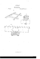
Be it known that I, TIMOTHY DWIGHT, of the city and county of New Haven and State of Connecticut, have invented a new and useful Improvement in Railroad-Tracks, and that the following is a full and clear description and representation thereof, reference being had to the annexed drawings, making part thereof, in whichw Figure 1 is an isometrical view. F ig. 2 is a longitudinal section showing the sill, rail, cross-tie &c. and Fig. 3 is a cross section of the same.
The manner in which I construct my railroad track is as follows, viz: After grading I lay down cross ties at about three feet apart; upon these I place stringers or sills of white oak or other very strong wood, six inches or more square in cross section, the sills being placed in notches prepared for them near the ends of the cross ties. In the upper side of the sills, about two inches apart I cut two longitudinal grooves the whole length of the track, these grooves should be about an inch in depth, and those nearest the outer edges of the sills should be about half an inch wide, and those on the inner side should be wide enough freely to admit the passage of the flange of the wheels intended for the road. The formation of these grooves will produce between them, along the middle of the upper side of the sill, a continuous tongue from end to end of the track. The ends of these sills where they meet are notched into each other directly over cross ties.
The rail which I use, is about an inch in thickness and something over two inches in width, having flanges at its edges, say half an inch thick extending downwards, say one inch, giving the rail the form of an inverted gutter. The dimensions of these flanges and the space between them, are to be such that they will accurately t over the tongue heretofore mentioned along the sill, and the flange will ft the outer groove thereof and rest in the bottom of the groove, while the middle line of the rail shall rest upon the upper surface of the tongue on the sill, and the inner flange shall rest upon the bottom of the inner groove in the sill. The rails are to be held to their places by screw bolts passing down through them and the sills and also through the cross ties, the heads of the bolts resting in countersinks so that they will be flush with the top of the rail and .the lower ends thereof, being secured by nuts. These screw bolts, not only serve the purpose of holding the parts in place as spikes would do, but in case of a tendency of any of the parts to work loose, and endanger the track, its integrity will immediately be restored by a turn of the nut.
At the ends of the rails, and also at the ends of the sills, the sills and rails breaking joints, the ribs on the sills on both adjacent ends are removed for a few inches, and their place supplied by a piece of iron, of the size of the rib or'tongue, and extending across the joint for the rail to rest on. At these joints the cross-ties are made wider than at intermediate points, that they may conveniently receive two bolts, one on each side of the joint.
In the accompanying drawings, c, represents the cross-ties, s, the sills, r the rails, b the bolts, t, the tongue or rib of the sills, z', the iron support, f, the flanges of the rail and f', the enlarged groove on the inside of the track. By thus making room in the sill for the flange of the wheel, this flange will work against the flange of the rail. One flange on the rail gainst which the flange of the wheel works, might answer the purpose, but I consider the form represented far better. By this construction' the strength and permanence of the T rail track may be at tained at vastly diminished expense.
Having thus fully described my rail-road track, what I claim therein as new and desire to secure by Letters Patent is,
The rail with its flange or fianges in combination with the sill adapted to fit the lower part of the rail as described; and these I also claim in combinations with the screw bolt and nut as described.
TIMOTHY DWIGHT.
Signed in presence of- ALMER AUSTIN, ELIJAH GILBERT.
Publications (1)
| Publication Number | Publication Date |
|---|---|
| US18577A true US18577A (en) | 1857-11-10 |
Family
ID=2082008
Family Applications (1)
| Application Number | Title | Priority Date | Filing Date |
|---|---|---|---|
| US18577D Expired - Lifetime US18577A (en) | Bail for railways |
Country Status (1)
| Country | Link |
|---|---|
| US (1) | US18577A (en) |
-
0
- US US18577D patent/US18577A/en not_active Expired - Lifetime
Similar Documents
| Publication | Publication Date | Title |
|---|---|---|
| DE2636853A1 (en) | RAILWAY CROSS TENSION | |
| US18577A (en) | Bail for railways | |
| US14868A (en) | Lock-joint for railroad-bars | |
| US26523A (en) | Bail fob stbeet-bailboads | |
| US25942A (en) | Bail fob bailboads | |
| US1594A (en) | William kits sell | |
| US147956A (en) | Improvement in railway-rails | |
| US530778A (en) | Timber railroad-tie | |
| US21241A (en) | Railroad-rail | |
| US51904A (en) | Improvement in construction of railways | |
| US21007A (en) | Improvement in compound rails for railroads | |
| Wright | American Street Railways: Their Construction, Equipment and Maintenance | |
| US999966A (en) | Railway-rail support. | |
| US1227689A (en) | Railroad-rail joint. | |
| US803611A (en) | Metallic railway-tie. | |
| US1277930A (en) | Railway-tie. | |
| US850373A (en) | Railway-track construction. | |
| US568619A (en) | Railway tie and clamp | |
| US317665A (en) | Built-up girder-rail | |
| US395304A (en) | Brotjgh | |
| US16490A (en) | Compound kail fob railroads | |
| US125304A (en) | Improvement in tram-ways for turnpikes | |
| US136227A (en) | Improvement in railroad crossings | |
| US1204904A (en) | Concrete-wood combination railroad-tie. | |
| US261737A (en) | Thomas p |