US1857720A - Rotary fluid compressor - Google Patents
Rotary fluid compressor Download PDFInfo
- Publication number
- US1857720A US1857720A US476388A US47638830A US1857720A US 1857720 A US1857720 A US 1857720A US 476388 A US476388 A US 476388A US 47638830 A US47638830 A US 47638830A US 1857720 A US1857720 A US 1857720A
- Authority
- US
- United States
- Prior art keywords
- support
- levers
- lever
- shifting
- toggle
- Prior art date
- Legal status (The legal status is an assumption and is not a legal conclusion. Google has not performed a legal analysis and makes no representation as to the accuracy of the status listed.)
- Expired - Lifetime
Links
- 239000012530 fluid Substances 0.000 title description 8
- 230000005484 gravity Effects 0.000 description 12
- 241000287181 Sturnus vulgaris Species 0.000 description 1
- 230000000694 effects Effects 0.000 description 1
Images


Classifications
-
- F—MECHANICAL ENGINEERING; LIGHTING; HEATING; WEAPONS; BLASTING
- F04—POSITIVE - DISPLACEMENT MACHINES FOR LIQUIDS; PUMPS FOR LIQUIDS OR ELASTIC FLUIDS
- F04B—POSITIVE-DISPLACEMENT MACHINES FOR LIQUIDS; PUMPS
- F04B27/00—Multi-cylinder pumps specially adapted for elastic fluids and characterised by number or arrangement of cylinders
- F04B27/04—Multi-cylinder pumps specially adapted for elastic fluids and characterised by number or arrangement of cylinders having cylinders in star- or fan-arrangement
- F04B27/06—Multi-cylinder pumps specially adapted for elastic fluids and characterised by number or arrangement of cylinders having cylinders in star- or fan-arrangement the cylinders being movable, e.g. rotary
-
- F—MECHANICAL ENGINEERING; LIGHTING; HEATING; WEAPONS; BLASTING
- F04—POSITIVE - DISPLACEMENT MACHINES FOR LIQUIDS; PUMPS FOR LIQUIDS OR ELASTIC FLUIDS
- F04B—POSITIVE-DISPLACEMENT MACHINES FOR LIQUIDS; PUMPS
- F04B27/00—Multi-cylinder pumps specially adapted for elastic fluids and characterised by number or arrangement of cylinders
- F04B27/02—Multi-cylinder pumps specially adapted for elastic fluids and characterised by number or arrangement of cylinders having cylinders arranged oppositely relative to main shaft
-
- F—MECHANICAL ENGINEERING; LIGHTING; HEATING; WEAPONS; BLASTING
- F04—POSITIVE - DISPLACEMENT MACHINES FOR LIQUIDS; PUMPS FOR LIQUIDS OR ELASTIC FLUIDS
- F04B—POSITIVE-DISPLACEMENT MACHINES FOR LIQUIDS; PUMPS
- F04B31/00—Free-piston pumps specially adapted for elastic fluids; Systems incorporating such pumps
-
- Y—GENERAL TAGGING OF NEW TECHNOLOGICAL DEVELOPMENTS; GENERAL TAGGING OF CROSS-SECTIONAL TECHNOLOGIES SPANNING OVER SEVERAL SECTIONS OF THE IPC; TECHNICAL SUBJECTS COVERED BY FORMER USPC CROSS-REFERENCE ART COLLECTIONS [XRACs] AND DIGESTS
- Y10—TECHNICAL SUBJECTS COVERED BY FORMER USPC
- Y10T—TECHNICAL SUBJECTS COVERED BY FORMER US CLASSIFICATION
- Y10T74/00—Machine element or mechanism
- Y10T74/18—Mechanical movements
- Y10T74/18056—Rotary to or from reciprocating or oscillating
- Y10T74/18232—Crank and lever
- Y10T74/1824—Slidable connections
Definitions
- My invention relates to pressors.
- An important objectof the invention is'to provide a machine of the above mentioned character having a high efficiency in operation.
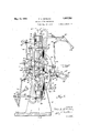
- FIG. 1 is a side elevation of the machine embodying my invention
- Figure 2 is an end elevation of the same
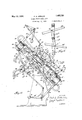
- Figure 3 is a vertical longitudinal section taken on line 33 of Figure 2, showing the rotating unit in the vertical position.
- Figure 4 is a similarview, showing the rotating unit disposed at an angle of about 45 from the vertical.
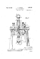
- Figure 5 is a transverse section taken on line 5-5 of Figure 3,
- FIG. 6 is a detailed longitudinal section through the connecting rod, 4
- Figure 7 is a side elevation of the rotary support or frame
- Figure 8 is a horizontal section taken on line 8-8 of Figure 5.
- the numeral IO designates a pair of standards mounted upon a suitable base 11 and provided at theirupper ends with bearings 12, for receiving the hori Zontal rotatable shaft sections 13 and 14.
- the machine embodies a rotatable unit, in-
- a pulley 19 may be rigidly mounted upon the shaft section 13 to rotate the unit and may be driven by any suitable means.
- a hollow annular drum 20 ismounted upon the shaft section 14 to rotate therewith, and is bolted or otherwise rigidly attached to the adjacent sleeve 18, as shown at 2l, and this drum is provided upon its outer side with an annular opening 22 in communication with a stationary annular drum 23,having a sliding gas-tight joint therewith, as shown at 24.
- An outlet pipe 25 is connected with the stationary drum 23 and may lead to any desired point.
- Each cylinder 15 is provided with an inwardly opening check valve-26 and an outwardly opening check valve 27, having connection with a pipe'28, connected with the rotary drum 20 and leading to the interior of the same. The air compressed within each cylinder 15 is thus fed to the rotary drum 20.
- plungers 29, Figure 5 Mounted to reciprocate within-the cylinder 15 are plungers 29, Figure 5, which are connected by a rigid straight line plunger rod 30, having an intermediate yoke portion 31', including spaced arms 32.
- This yoke portion I and associated elements operates between the flanges 17, and the plunger rod reciprocates during the rotation of the unit, for effecting the movement of the plungers.
- the numerals 39 and 39 designate shifting or centralizing levers, extendingtransversely of the arms or frame connecting the cylinders, and projecting beyond the: opposite sides of'the frame, as shown.
- the lever 39 is supported, by the pivot 40, carriedby a lug of bracket 41, formed upon the cylinder frame.
- the lever 39- has its right end, Figure 4, extending for a greater distance beyond the side of thecylinder frame than its left end, as shown. 7
- the lever39 extends transversely of the cylinderframe and is supported by a pivot 42, carried by a lug or bracket; 43 secured to the cylinder frame.
- the left end of the lever 39, Figure 4 extends for a greater distance beyond the side of the cylinder "frame than its right end.
- brace shifting lever 39 see particularly Figure 6,.
- the numerals 46 and 46 designate actuat- 7 ing levers, pivotally mounted upon the cylinder frame, as shown at 4?, near the cylinders.
- a link v49 is pivotally connected with the actuating lever 46, as shown at 50, and is pivotally connected with the short arm of the shift ng lever 39,
- a link 51 is :pivotally connected with the actuating lever 46, as shown at 52, and is pivotally connected with the short arm of the shifting lever 39, as shown at 53.
- actuating levers are operated by gravity and act upon the shifting levers 39 to swing their long arms in the same direction.
- Weight operated toggle joints 54 and 54 are connected with the shifting levers 39 and 39;
- lever 54 has pivotal connection, as shown at 56, with a link 57, which is pivoted to the long arm of the lever 39, as shown at 58.
- An L-shaped arm 59 is connected with the link 57 by the'same pivot or pin 56, and is con- 60, which brace is connected with the link 57, as shown at 61.
- the L-shaped arm 59 is with the link 57'.
- the L-shaped arm 59 carries a weight 62 at its outer end.
- the angular position that the Lshaped arm 59 has, with respect to the link 57 remains fixed.
- the toggle joint connected with the long arm of the shifting lever 39 is identical with the toggle joint, thus described, and embodies a lever 54, link 57, and L-shaped arm 59-. It is thought to be unnecessary to
- Means are provided for openingor breaking each toggle'joint, comprising a lever 63, pivoted between its ends to the cylinder frame, as shown at 64, and carrying a weight 65, at its inner end. Pivotallyconnected with the outer end of each lever 63 is a link 66, the inner end of which is longitudinally slotted, asshown at 67, and this slotted end operates within a strap 68, attached tothe lever 54 and to the lever 54'.
- a 'pin 69 extends through each lever 54 and 54 and operates within the slot 67.
- This supporting unit is preferably rotated at about 24 R. P. M.
- the supporting unit is shown in the vertical position, in Figure 3, with toggle joint 54", open and toggle oint 54 closed, the lower piston 29 being in the inner position.
- the lever 63, connected with the toggle joint 54 has its outer end moved upwardly by the weight 65, raising lever 54 whereby lever 54 and link 57 are drawn out of the straight line position to angular positions, thus breaking the toggle joint, and allowing the weight 62 to shift the toggle joint to the completely open position, shown in Figure 4.
- toggle joints 54 and 54 remain in this condition until the supporting unit is again turned past the vertical position, shown in Figure 3, at which time the toggle joint 54 will close wvette toggle joint 54 will open and the plungers again shifted to the opposite ends of the cylinders.
- the movement of the shifting levers 39 and 39 is also aided by the bell crank levers 34 and 34.
- a rotary support including reciprocatory elements, a rod connecting thereciprocatory elements, shifting levers pivotally mounted upon the support, a link connected with the rod and the shifting levers, weight carrying levers pivoted upon the support and connected with the shifting levers to move the same, and weight carrying toggle joints pivoted upon the support and connected with the shifting levers.
- a rotary support means'mounted upon the support near its ends, including reciprocatory elements, a rod connecting the reciprocatory elements, shifting levers extendingtransversely of the support and pivotally connected therewith and having long arms extending in opposite directions, means pivotally connecting such long arms with the 7 rod, weight carrying levers pivotally mounted upon-the support and extending upon opposite sides of the same and pivotally connected with the short arms of the shifting levers, toggle joints carrying weights and pivotally connected with the support and ex-' tending upon opposite sides of the same and pivotally connected with the long. arms of the shifting levers, and automatic means to break the toggle joints outwardly.
- a rotatable support means mounted upon the same near its ends, including reciprocatory elements, a plunger rod connecting reciprocatory elements, shifting levers pivotally mounted upon the support, each shifting lever having short and long arms. the long arms of the shifting levers extending in opposite directions, a gravity operated element mounted upon the support and connected with the short arm of each shifting lever, toggle joints pivotally mounted upon the support and connected with the long arms of said levers, Weights carried by the toggle joints, bell crank levers pivoted upon the support and having their outer arms facing toward the toggle joints, weights carried by said outer arms. links connecting the inner arms of the bell crank levers with the long arms of the shiftinglevers and means connecting the shiftin levers with the rod.
- a rotatable support means mounted upon the support. including reciprocatory elements. a rod connecting the reciprocatorv elements. shifting levers pivoted upon the support. each shifting lever having short and long arms. the lon arms extending in opposite directions. a link pivotallv connected with the shifting levers and rod, and gravity oper- 6.
- a rotatable support means mounted upon the support, including reciprocatory elements, a rod connecting the plungers, shifting levers pivoted upon the support, a link pivotally.
- a rotatable support including reciprocatory elements, shifting levers pivoted upon the support and serving to operate the reciprocatory elements, and gravity operated devices carried by ther'otatable support and connected with the shifting levers.
- a rotatable support including reciprocatory elements, means mounted thereon including reciprocatory elements, a shifting lever pivoted upon the support for operating the reciprocatory elements, and a gravity. operated device carried by the support and com 'nected with the shifting lever, said gravity operated device including a toggle joint.
- a rotatable support including reciprocatory elements, means mounted thereon including reciprocatory elements, and a gravity operated toggle joint carried by the support and operating the reciprocatory elements.
- a rotary support,means mounted thereon including a reciprocatory element, a lever pivoted upon the support and having a long arm connected with the reciprocatory element, and a gravity operated device for moving the lever, said device including a gravity operated toggle joint.
Landscapes
- Engineering & Computer Science (AREA)
- Mechanical Engineering (AREA)
- General Engineering & Computer Science (AREA)
- Press Drives And Press Lines (AREA)
Description
May 10, 1932. F. A. GERLING ROTARY FLUID COMPRESSOR Filed Aug. '19, 1930 SSheets-Sheet 1 INVENTOR. fkm A. 65m uva,
ATTORNEY May 10, 1932.
F A. GERLING ROTARY FLUID COMPRESSOR Filed Aug. 19, 1.930
5 Sheets-Sheet 2 INVENTOR. [H0 A. GERL/NG )E BY 4 414% ATTORNEY.
May 10, 1932. GERLING 1,857,720
ROTARY FLUID CONIPRESSOR Filed Aug. 19, 1930 5 Sheets-Sheet 3 IBM". 1 3 INVEZVTOR,
H [km A. GERL/NG,
/r 3/ W ATTORNEY.
May 10, 1932. F. A. GERLING 1,857,720
ROTARY FLUID COMPRESSOR Filed Aug. 19, 1950 s Sheets-Sheet 4 INVENTOR. 27850 A 65m nva .4 TTORNEY.
BY. W4
May 10,1932. A, RUN 1,857,720
ROTARY FLUID COMPRESSOR Filed Aug. 19, 1930 5 Sheets-Sheet 6 as I 27 a a N 1 N VENTOR. flaw/i. GERL/NG,
W4 Mai/ T ATTORNEY.
* untrue stares Patented May 10, 193 2 FRED A. GER/LING, OF BOISE, IDAHO ROTARY FLUID COMPRESSOR Applicationfiled August 19, 1930. Serial No. 476,388.
My invention relates to pressors.
An important objectof the invention is'to provide a machine of the above mentioned character having a high efficiency in operation.
In the accompanying drawings, forming a part of this specification, and in which like numerals are employed to designate like parts throughout the-same, v
Figure 1 is a side elevation of the machine embodying my invention,
Figure 2 is an end elevation of the same,
Figure 3 is a vertical longitudinal section taken on line 33 of Figure 2, showing the rotating unit in the vertical position.
Figure 4 is a similarview, showing the rotating unit disposed at an angle of about 45 from the vertical.
Figure 5 is a transverse section taken on line 5-5 of Figure 3,
Figure 6 is a detailed longitudinal section through the connecting rod, 4
Figure 7 is a side elevation of the rotary support or frame, and,
Figure 8 is a horizontal section taken on line 8-8 of Figure 5.
In the drawings, wherein for the purpose of illustration, is shown a: preferred embodiment of my invention, the numeral IO-designates a pair of standards mounted upon a suitable base 11 and provided at theirupper ends with bearings 12, for receiving the hori Zontal rotatable shaft sections 13 and 14.
rotary fluid com- The machine embodies a rotatable unit, in-
eluding a pair of cylinders 15, which are rigidly connected with arms 16, the intermediate portions of which are rigidly connected with flanges 17, formed upon sleeves 18. These sleeves are rotatable with the shaft sections 13 and 14.
A pulley 19 may be rigidly mounted upon the shaft section 13 to rotate the unit and may be driven by any suitable means. A hollow annular drum 20 ismounted upon the shaft section 14 to rotate therewith, and is bolted or otherwise rigidly attached to the adjacent sleeve 18, as shown at 2l, and this drum is provided upon its outer side with an annular opening 22 in communication with a stationary annular drum 23,having a sliding gas-tight joint therewith, as shown at 24. An outlet pipe 25=is connected with the stationary drum 23 and may lead to any desired point. 1 Each cylinder 15 is provided with an inwardly opening check valve-26 and an outwardly opening check valve 27, having connection with a pipe'28, connected with the rotary drum 20 and leading to the interior of the same. The air compressed within each cylinder 15 is thus fed to the rotary drum 20.
Mounted to reciprocate within-the cylinder 15 are plungers 29, Figure 5, which are connected by a rigid straight line plunger rod 30, having an intermediate yoke portion 31', including spaced arms 32. This yoke portion I and associated elements operates between the flanges 17, and the plunger rod reciprocates during the rotation of the unit, for effecting the movement of the plungers.
Rigidly connected with the cylinders 15, and preferably formed integral therewith, are supporting arms 33,,disposed at a right angle to the axes of the cylinders and facing in opposite directions with relation to each other. Bell crank levers 34 and 34' are pivotally mounted upon the outer end of the arms 33, as shown at 35, and these bell crank levers carry weights 36, at their free ends. :3
7 These bell crank levers have pivotal connection at'their opposite freeen'd, as shown at 37, With links 38 and 38". 1 I The numerals 39 and 39 designate shifting or centralizing levers, extendingtransversely of the arms or frame connecting the cylinders, and projecting beyond the: opposite sides of'the frame, as shown. The lever 39 is supported, by the pivot 40, carriedby a lug of bracket 41, formed upon the cylinder frame. The lever 39- has its right end, Figure 4, extending for a greater distance beyond the side of thecylinder frame than its left end, as shown. 7 The lever39 extends transversely of the cylinderframe and is supported by a pivot 42, carried by a lug or bracket; 43 secured to the cylinder frame. The left end of the lever 39, Figure 4, extends for a greater distance beyond the side of the cylinder "frame than its right end. The
'nected with a brace shifting lever 39, see particularly Figure 6,.
arm of the shifting lever 39, assho'wn at 45.
The numerals 46 and 46 designate actuat- 7 ing levers, pivotally mounted upon the cylinder frame, as shown at 4?, near the cylinders.
These actuatin levers carr wei hts'48 u 30H their outer ends. A link v49 is pivotally connected with the actuating lever 46, as shown at 50, and is pivotally connected with the short arm of the shift ng lever 39,
as shown at 51. In a corresponding manner, a link 51 is :pivotally connected with the actuating lever 46, as shown at 52, and is pivotally connected with the short arm of the shifting lever 39, as shown at 53. These actuating levers are operated by gravity and act upon the shifting levers 39 to swing their long arms in the same direction.
Weight operated toggle joints 54 and 54 are connected with the shifting levers 39 and 39; The toggle joint connected with the shifting lever ner end of which is pivoted upon the cylinder frame, as shown at 55. lever 54 has pivotal connection, as shown at 56, with a link 57, which is pivoted to the long arm of the lever 39, as shown at 58. An L-shaped arm 59 is connected with the link 57 by the'same pivot or pin 56, and is con- 60, which brace is connected with the link 57, as shown at 61. The L-shaped arm 59 is with the link 57'. The L-shaped arm 59 carries a weight 62 at its outer end. The angular position that the Lshaped arm 59 has, with respect to the link 57, remains fixed. The toggle joint connected with the long arm of the shifting lever 39 is identical with the toggle joint, thus described, and embodies a lever 54, link 57, and L-shaped arm 59-. It is thought to be unnecessary to further describe this identical toggle joint.
Means are provided for openingor breaking each toggle'joint, comprising a lever 63, pivoted between its ends to the cylinder frame, as shown at 64, and carrying a weight 65, at its inner end. Pivotallyconnected with the outer end of each lever 63 is a link 66, the inner end of which is longitudinally slotted, asshown at 67, and this slotted end operates within a strap 68, attached tothe lever 54 and to the lever 54'. A 'pin 69 extends through each lever 54 and 54 and operates within the slot 67.
The operation of the machine is as follows:
39 embodies a lever 54, the in-- The outer end of the in effect rigidly connected.
invention,
The supporting ders and cylinder clockwise in the direction of ures 3 and 4. This supporting unit is preferably rotated at about 24 R. P. M. The supporting unit is shown in the vertical position, in Figure 3, with toggle joint 54", open and toggle oint 54 closed, the lower piston 29 being in the inner position. When the supporting unit is turned to the left past the vertical position, at an angle of about 45 from tne vertical, the lever 63, connected with the toggle joint 54 has its outer end moved upwardly by the weight 65, raising lever 54 whereby lever 54 and link 57 are drawn out of the straight line position to angular positions, thus breaking the toggle joint, and allowing the weight 62 to shift the toggle joint to the completely open position, shown in Figure 4. The opening of the toggle oint draws the long arm of the shifting lever 39 upwardly, aided by the action of the weight 48, due to gravity. When the toggle joint 54 thus opens or breaks, the toggle 54 closes, the link frame is rotated counterthe arrow, Fig- 57" acting upon the long arm of the shifting lever 39, moving it upwardly, and this movement of the shifting lever 39 is aided by the gravity operated weight 48, connected with its short arm. It isthusseen that the long arms of the shifting levers 39 and 39 are both moved upwardly, in the same direction, thereby shifting the plungers 29 to the opposite ends of the cylinders. The toggle joints 54 and 54 remain in this condition until the supporting unit is again turned past the vertical position, shown in Figure 3, at which time the toggle joint 54 will close wiile toggle joint 54 will open and the plungers again shifted to the opposite ends of the cylinders. The movement of the shifting levers 39 and 39 is also aided by the bell crank levers 34 and 34.
it is to be understood that the form of my herewith shown and described, is to be taken-as a preferred example of the same, and that various changes in the shape, size and arrangement of parts, may be resorted to, without departing from the spirit of my invention, or the. scope of the subjoined claims.
' Having thus claim 2- 1. in a device of the character described, a rotary support, means mounted thereon, including reciprocatory elements, a rod connecting thereciprocatory elements, shifting levers pivotally mounted upon the support, a link connected with the rod and the shifting levers, weight carrying levers pivoted upon the support and connected with the shifting levers to move the same, and weight carrying toggle joints pivoted upon the support and connected with the shifting levers.
2. In a device of the character described,
described my invention, a I
unit, including the cylinwhich movement is also 7 a rotary support, means mounted thereon, including reciprocatoryelements, arod connecting the reciprocatory elements, shifting levers pivoted upon the support, means connecting the shifting levers with the rod, weight carrying levers pivoted upon the support and connected with the shifting levers to move the same, weight carrying toggle joints pivoted upon the support and connected with the shifting levers and Weight carrying elements pivoted upon the support and connected with the toggle joints to break the same outwardly. 1
3. In a device of the character described, a rotary support, means'mounted upon the support near its ends, including reciprocatory elements, a rod connecting the reciprocatory elements, shifting levers extendingtransversely of the support and pivotally connected therewith and having long arms extending in opposite directions, means pivotally connecting such long arms with the 7 rod, weight carrying levers pivotally mounted upon-the support and extending upon opposite sides of the same and pivotally connected with the short arms of the shifting levers, toggle joints carrying weights and pivotally connected with the support and ex-' tending upon opposite sides of the same and pivotally connected with the long. arms of the shifting levers, and automatic means to break the toggle joints outwardly.
4. In a device of the character described, a rotatable support, means mounted upon the same near its ends, including reciprocatory elements, a plunger rod connecting reciprocatory elements, shifting levers pivotally mounted upon the support, each shifting lever having short and long arms. the long arms of the shifting levers extending in opposite directions, a gravity operated element mounted upon the support and connected with the short arm of each shifting lever, toggle joints pivotally mounted upon the support and connected with the long arms of said levers, Weights carried by the toggle joints, bell crank levers pivoted upon the support and having their outer arms facing toward the toggle joints, weights carried by said outer arms. links connecting the inner arms of the bell crank levers with the long arms of the shiftinglevers and means connecting the shiftin levers with the rod.
5. In a device of the character described. a rotatable support, means mounted upon the support. including reciprocatory elements. a rod connecting the reciprocatorv elements. shifting levers pivoted upon the support. each shifting lever having short and long arms. the lon arms extending in opposite directions. a link pivotallv connected with the shifting levers and rod, and gravity oper- 6. In a device of the character described,
a rotatable support, means mounted upon the support, including reciprocatory elements, a rod connecting the plungers, shifting levers pivoted upon the support, a link pivotally.
connected with the rod andshifting levers, and gravity operated. devices mounted upon the support and connected with the shifting levers to move the same. 1 v
7. In a device of the character described, a rotatable support, means mounted thereon including reciprocatory elements, shifting levers pivoted upon the support and serving to operate the reciprocatory elements, and gravity operated devices carried by ther'otatable support and connected with the shifting levers. u
8. In a device of the character-described, a rotatable support, including reciprocatory elements, means mounted thereon including reciprocatory elements, a shifting lever pivoted upon the support for operating the reciprocatory elements, and a gravity. operated device carried by the support and com 'nected with the shifting lever, said gravity operated device including a toggle joint.
9. In a device of the character described, a rotatable support, including reciprocatory elements, means mounted thereon including reciprocatory elements, and a gravity operated toggle joint carried by the support and operating the reciprocatory elements.
10.- In a device of thecharacter described, a rotary support,means mounted thereon including a reciprocatory element, a lever pivoted upon the support and having a long arm connected with the reciprocatory element, and a gravity operated device for moving the lever, said device including a gravity operated toggle joint.
In testimony whereof I affix my signature.
FRED A. GERLING.
Priority Applications (1)
| Application Number | Priority Date | Filing Date | Title |
|---|---|---|---|
| US476388A US1857720A (en) | 1930-08-19 | 1930-08-19 | Rotary fluid compressor |
Applications Claiming Priority (1)
| Application Number | Priority Date | Filing Date | Title |
|---|---|---|---|
| US476388A US1857720A (en) | 1930-08-19 | 1930-08-19 | Rotary fluid compressor |
Publications (1)
| Publication Number | Publication Date |
|---|---|
| US1857720A true US1857720A (en) | 1932-05-10 |
Family
ID=23891627
Family Applications (1)
| Application Number | Title | Priority Date | Filing Date |
|---|---|---|---|
| US476388A Expired - Lifetime US1857720A (en) | 1930-08-19 | 1930-08-19 | Rotary fluid compressor |
Country Status (1)
| Country | Link |
|---|---|
| US (1) | US1857720A (en) |
Cited By (4)
| Publication number | Priority date | Publication date | Assignee | Title |
|---|---|---|---|---|
| US4449894A (en) * | 1979-05-08 | 1984-05-22 | The United States Of America As Represented By The Administrator Of The National Aeronautics And Space Administration | Centrifugal-reciprocating compressor |
| US5484268A (en) * | 1988-11-14 | 1996-01-16 | Impact Mst Incorporated | Positive displacement centrifugal pump |
| US20060239832A1 (en) * | 2005-04-21 | 2006-10-26 | Guy Uriel | Compressed air power generating systems using a rotary gravity compressor |
| CN103267005A (en) * | 2013-06-19 | 2013-08-28 | 上海理工大学 | Reciprocating centrifugal compressor |
-
1930
- 1930-08-19 US US476388A patent/US1857720A/en not_active Expired - Lifetime
Cited By (5)
| Publication number | Priority date | Publication date | Assignee | Title |
|---|---|---|---|---|
| US4449894A (en) * | 1979-05-08 | 1984-05-22 | The United States Of America As Represented By The Administrator Of The National Aeronautics And Space Administration | Centrifugal-reciprocating compressor |
| US5484268A (en) * | 1988-11-14 | 1996-01-16 | Impact Mst Incorporated | Positive displacement centrifugal pump |
| US20060239832A1 (en) * | 2005-04-21 | 2006-10-26 | Guy Uriel | Compressed air power generating systems using a rotary gravity compressor |
| CN103267005A (en) * | 2013-06-19 | 2013-08-28 | 上海理工大学 | Reciprocating centrifugal compressor |
| CN103267005B (en) * | 2013-06-19 | 2016-06-15 | 上海理工大学 | A kind of back and forth radial compressor |
Similar Documents
| Publication | Publication Date | Title |
|---|---|---|
| US1857720A (en) | Rotary fluid compressor | |
| US2630986A (en) | Wing control for aircraft | |
| US2075819A (en) | Full-swing crane | |
| US1615140A (en) | Pump or motor | |
| US2240010A (en) | Vulcanizer | |
| US3209842A (en) | Apparatus for rotating a shaft with fluid pressure cylinders | |
| US2184200A (en) | Counterrotating counterbalance | |
| US2152762A (en) | Straight lift pumping apparatus | |
| US1382309A (en) | Straightening-machine | |
| US1615284A (en) | Shoveling machine | |
| US493928A (en) | Edward heyde | |
| US1609250A (en) | Pull rod pump jack | |
| US2523444A (en) | Pumping unit | |
| US1953903A (en) | Pumping jack | |
| US2722850A (en) | Power reducer for pumping wells | |
| US2057851A (en) | Sprinkler | |
| US92508A (en) | Improved excavating-machine | |
| US2244812A (en) | Well pump operating apparatus | |
| US349597A (en) | lidback | |
| US1729664A (en) | Pump jack | |
| US1435462A (en) | Revolving compressor | |
| US1395954A (en) | Ventilating signal appliance for mines | |
| US1761330A (en) | Long-stroke pumping mechanism | |
| US538068A (en) | denney | |
| US2048119A (en) | Straight line pumping jack |