US1857714A - Carding device for artificial teeth - Google Patents
Carding device for artificial teeth Download PDFInfo
- Publication number
- US1857714A US1857714A US499383A US49938330A US1857714A US 1857714 A US1857714 A US 1857714A US 499383 A US499383 A US 499383A US 49938330 A US49938330 A US 49938330A US 1857714 A US1857714 A US 1857714A
- Authority
- US
- United States
- Prior art keywords
- tooth
- card
- teeth
- lugs
- artificial teeth
- Prior art date
- Legal status (The legal status is an assumption and is not a legal conclusion. Google has not performed a legal analysis and makes no representation as to the accuracy of the status listed.)
- Expired - Lifetime
Links
Images

Classifications
-
- A—HUMAN NECESSITIES
- A61—MEDICAL OR VETERINARY SCIENCE; HYGIENE
- A61C—DENTISTRY; APPARATUS OR METHODS FOR ORAL OR DENTAL HYGIENE
- A61C19/00—Dental auxiliary appliances
- A61C19/10—Supports for artificial teeth for transport or for comparison of the colour
Definitions
- the object of my invention is to provide a mount or card device for artificial teeth, which is substantially rigid in constructionand will not easily bend or break.
- a further object of my invention is to provide such a mount which will notsoil the teeth.
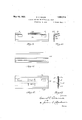
- Figure MS a longitudinal sectional View of the front member with the tooth holding elemy invention is topro-- ment attached, and said elementbeing shown in full and dotted lines in applied and partly applied positions.
- FIG. 6 is a vertical sectional view of Figure 1, with a tooth in place thereon.
- Figure 8 is a. vertical transverse sectional shownin Figure 7.'
- Figure 9. is a'front elevation ofmy mount Figure 10lis an end elevation Figure I Figure 11 is a front elevation of the mount shown in Figure 8.
- v J Figure 12 is a front elevation showinganother embodiment of my invention.
- the reference numeral 15 designates.
- This element which shall hereinafter designatethetooth card, is. crimped lengthwise to form'a groove 18.
- This groove may be formed by crimping, em bossing or many. other desired manners.
- the lug strip 21 is crimped at predetermined points throughout its length, to form lugs 22.
- lugs 22 For purp oses of illustration I have shown but two of these lugs, but it will be understood that any desired number may be formed in the strip.
- the strip 21 is laid in the groove 18 of the tooth card and the lugs 22 are forced through the slots 20 in the front wall of the groove 18, by any suitable means, as clearly shown in Figure 5. It will be noted, as shown in Figure 5, these lugs 22 after being passed through the slots .20, assume a more or less bulbous shape with a restricted neck 23 at and near the plane of the outer face of the wall 19 of-the groove. This shape maybe termed dovetail for'the want of a better term.
- the tooth card is mounted in the grooves formed by the flanges 1 6, and thus firmly secured to the back plate 15, as shown in Figure 2, thelugs being in position to receive and hold teeth on the mount, as shown in Figures 1 and 6.
- an important feature of. my invention consists in providing a lug strip which is formed from cardboard or like sheet fibrous material, from which the lugs are projected by a crimping or other offsetting action, such material having a certain degree ofresiliency so that it normally maintains its shape, adapting each lug to yield and contract underpressure'and to resume its normal or bulbous shape after the pressure is removed;
- FIGS. 12 and 13 show still another embodiment'in which the metal backing 15 has a plurality of grooves 24 formed in it, in
- a tooth card embodying my invention may take any form and be shaped flat or with one or more angles, to accommodate a particular type of tooth.
- the card may also be formed with openings A through which may be displayed a suitable designation as to the mould and shade number of the tooth displayed, as provided in the Moyer Patent No..1,721,526, of July'23, 1927, and such designation being printed-on a strip B.
- the tooth supporting lugs '22 are characterized by the fact that the lugs being made of a somewhat resilient non-metallic material which is softer and more yieldingthan the porcelain of the tooth they offer less resistance than the porcelain of the tooth and that, therefore, if one pulls the tooth transversely or at any other angle to the longitudinalaxis of the lug, the lug readily distorts and permits the tooth to be removed without any danger of spa'l'ling the tooth.
- the teeth have a hole and slot'complementary to the lug.
- A. carding device for artificial teeth comprising an oblong rectangular backing plate having flanges along its longitudinal edges, a correspondingly shaped card covering the faceof said plate.and-heldinentending transversely thereof, and a tooth re taining strip of wood fibreeXtend-ing longitudinally between the backing plate and card and doubled. at intervals to provide dove- 110 doubled at intervals to provide dovetailed yielding tooth receiving and supporting lugs tailed yielding tooth receiving and supporting lugs projecting through said slots beyond the face of the card.
- a carding device for artificial teeth comprising a backing, a card secured to the backing, the card and backing being bent to provide tooth engaging surfaces arranged at an angle to each other, one of said surfaces of the card having slots therein, and a tooth retaining strip between said surface and the back doubled at intervals to provide yielding tooth receiving and supporting lugs pro- 1ecting through said slots beyond the face of the card.
Description
2 Sheets-Sheet 1 Filed Dec. 1, 1950 May 10, 1932.
v 6 m M 5 W 5 E a a HW vN wMMRvuRv vuw/ ,UNITED STATES PATENT. OFF-Ion, I
.Patented May 10, I932 DAVID E. VAN OZECOLUMBUS, OHIO, AssIGNon 'ro THE ooLcMBUs 13mm:- MANU- "FACTURING COMPANY, or oo UMnUs, onro, n CORPORATION CABDING- DEVICE iron. ARTIFICIAL TEETH.
Application filed December 1, 1930. Serial No. 499,3 83. I
I Heretofore artificial teeth have been mounted on a card'or. the like, formed of cardboard, metal or Wood in. combination With wax or other penetrable material, or having a coating of such material thereon, the teeth being pressed into the wax and being held therebyon the card. This method of mounting the teeth is not satisfactory in warm weather, the wax becomes too soft. and easily or mounting teeth consists of amount of cardboard, Wood ormetal, having split metal pins.- 1 i *Another method consists of amount havingspring metal flanges. Theselast twov methods are unsatisfactory because persons often in removing the teeth from themount pull the teeth transversely of the mount in removing them, instead of in the plane of the mount, which results in. chipping the teeth 1.1; when they are thus removed.
The object of my invention is to provide a mount or card device for artificial teeth, which is substantially rigid in constructionand will not easily bend or break.
A further object of my invention is to provide such a mount which will notsoil the teeth. V A further'object of vide amount for teeth which will eliminate :i chipping of-- the teeth when the teeth are .re-:
Figure MS a longitudinal sectional View of the front member with the tooth holding elemy invention is topro-- ment attached, and said elementbeing shown in full and dotted lines in applied and partly applied positions.
I Figure 6. is a vertical sectional view of Figure 1, with a tooth in place thereon.
View of a holding device embodying my invention, adapted to hold anothertype of tooth.
' Figure 8 is a. vertical transverse sectional shownin Figure 7.' I
Figure 9.is a'front elevation ofmy mount Figure 10lis an end elevation Figure I Figure 11 is a front elevation of the mount shown inFigure 8. v J Figure 12 is a front elevation showinganother embodiment of my invention.
' F1gure-13 is-an end elevation of Figure 1.2. i
The reference numeral 15 designates. the
back plate of my improved carding device for artificial teeth, whichfmay be made of any suitable substantially stiff material, such, for instance, as metal, that willnot easilylbend or break. This backing ,is provided at its upper and loweredgesvvith rebent'edges 16 View of another embodiment of my invention.
disposed on its face side and spaced there- Y from to form grooves inwhich a strip of cardboard 17 or other-rsuitable materialwisi held to the back15. This element, which shall hereinafter designatethetooth card, is. crimped lengthwise to form'a groove 18. This groove may be formed by crimping, em bossing or many. other desired manners. The
1 front wall 19' of the groove jislpr'ovided with thedesired number of slots 20, extending .ver-' .tically, asf-clearly shown inFigure In Figure 4 I have illustrated, in top plan, a lug strip, or'ribbon 21, which comprises a comparativelynarrow strip of non-metallic material (preferably cardboard orv like paper.
vor fairly soft fibrous ;material) .v'vhichis'of such thickness. and width that it lies snugly within the groove 18 and .isisubstantially" flush with the P ne of the rear face of: the 976 will be avoided.
' tooth.
tooth card, as clearly shown in Figure 2. The lug strip 21 is crimped at predetermined points throughout its length, to form lugs 22. For purp oses of illustration I have shown but two of these lugs, but it will be understood that any desired number may be formed in the strip. The strip 21 is laid in the groove 18 of the tooth card and the lugs 22 are forced through the slots 20 in the front wall of the groove 18, by any suitable means, as clearly shown in Figure 5. It will be noted, as shown in Figure 5, these lugs 22 after being passed through the slots .20, assume a more or less bulbous shape with a restricted neck 23 at and near the plane of the outer face of the wall 19 of-the groove. This shape maybe termed dovetail for'the want of a better term. After the lugs are passed through the slots, the tooth card is mounted in the grooves formed by the flanges 1 6, and thus firmly secured to the back plate 15, as shown in Figure 2, thelugs being in position to receive and hold teeth on the mount, as shown in Figures 1 and 6.
" It will thus be understood that an important feature of. my invention consists in providing a lug strip which is formed from cardboard or like sheet fibrous material, from which the lugs are projected by a crimping or other offsetting action, such material having a certain degree ofresiliency so that it normally maintains its shape, adapting each lug to yield and contract underpressure'and to resume its normal or bulbous shape after the pressure is removed; By this means it will be evident that the lug will yield when the tooth supported thereby isflpulled transversely away from' it, instead of sliding it off the lug, and thereby permit the tooth tobe idetached,..and, as the cardboard or similar fibrous material used: is comparatively soft,
and much softer than the porcelain of which the tooth ismade, all liability of the edges of the teeth being chipped when the are removed Moreover, the described type oflug stripmay be easily and cheaply made andapplied for use with great facility. I-n Figures 7 and 10 thedetails of structure of the several parts, such as the plate 15 tooth card 17 having the groove 18, lug strip 21 lugs 22 are substantially the same as hereinbefore described, with the exception that the mount as a whole is bent at anangle to suit a particular and well known type of The same is true as to the mount shown in Figures 8 and 11, in which I have designated the metal backing with 15 having three bends. The toothcard 15 shown in these figures, is of the same construction as heretofore described, except that it is shaped to r the backing;-
I Figures 12 and 13 show still another embodiment'in which the metal backing 15 has a plurality of grooves 24 formed in it, in
which the lug strip 21 is seated with the lugs card 17 It will, of course, be understood that a tooth card embodying my invention may take any form and be shaped flat or with one or more angles, to accommodate a particular type of tooth. The card may also be formed with openings A through which may be displayed a suitable designation as to the mould and shade number of the tooth displayed, as provided in the Moyer Patent No..1,721,526, of July'23, 1927, and such designation being printed-on a strip B.
As will be understood from the above the tooth supporting lugs '22 are characterized by the fact that the lugs being made of a somewhat resilient non-metallic material which is softer and more yieldingthan the porcelain of the tooth they offer less resistance than the porcelain of the tooth and that, therefore, if one pulls the tooth transversely or at any other angle to the longitudinalaxis of the lug, the lug readily distorts and permits the tooth to be removed without any danger of spa'l'ling the tooth. As far as I know I am the first to provide such a tooth supporting lug. The teeth have a hole and slot'complementary to the lug.
It is to be understood that my inventions-is adapted for use with any size of'card that may be used in association with shippi-ng boxes for teeth, whereby the teeth are held firmly in position during VVhat I claim is: j LA carding device for artificial teeth comprising an oblong rectangular backing shipment.
plate having flanges alon its longitudinal edges, a correspondingly s aped card covering-the face of said plate-and held in engagement therewith by said flanges, said cardbeing formed at intervals with slots extending transversely thereof, and a'tooth retainingstrip of wood fiber extending longitudinally between the backing-plateand card and projecting through said slots beyond the face ofthecad. a
2. A. carding device for artificial teeth comprising an oblong rectangular backing plate having flanges along its longitudinal edges, a correspondingly shaped card covering the faceof said plate.and-heldinentending transversely thereof, and a tooth re taining strip of wood fibreeXtend-ing longitudinally between the backing plate and card and doubled. at intervals to provide dove- 110 doubled at intervals to provide dovetailed yielding tooth receiving and supporting lugs tailed yielding tooth receiving and supporting lugs projecting through said slots beyond the face of the card.
3. A carding device for artificial teeth comprising a backing, a card secured to the backing, the card and backing being bent to provide tooth engaging surfaces arranged at an angle to each other, one of said surfaces of the card having slots therein, and a tooth retaining strip between said surface and the back doubled at intervals to provide yielding tooth receiving and supporting lugs pro- 1ecting through said slots beyond the face of the card. I
In testimony whereof I afiix my signature.
DAVID E. EVANS.
Priority Applications (1)
| Application Number | Priority Date | Filing Date | Title |
|---|---|---|---|
| US499383A US1857714A (en) | 1930-12-01 | 1930-12-01 | Carding device for artificial teeth |
Applications Claiming Priority (1)
| Application Number | Priority Date | Filing Date | Title |
|---|---|---|---|
| US499383A US1857714A (en) | 1930-12-01 | 1930-12-01 | Carding device for artificial teeth |
Publications (1)
| Publication Number | Publication Date |
|---|---|
| US1857714A true US1857714A (en) | 1932-05-10 |
Family
ID=23985064
Family Applications (1)
| Application Number | Title | Priority Date | Filing Date |
|---|---|---|---|
| US499383A Expired - Lifetime US1857714A (en) | 1930-12-01 | 1930-12-01 | Carding device for artificial teeth |
Country Status (1)
| Country | Link |
|---|---|
| US (1) | US1857714A (en) |
Cited By (1)
| Publication number | Priority date | Publication date | Assignee | Title |
|---|---|---|---|---|
| US4306860A (en) * | 1979-11-22 | 1981-12-22 | Dentsply Research & Development Corp. | Mount for artificial teeth |
-
1930
- 1930-12-01 US US499383A patent/US1857714A/en not_active Expired - Lifetime
Cited By (1)
| Publication number | Priority date | Publication date | Assignee | Title |
|---|---|---|---|---|
| US4306860A (en) * | 1979-11-22 | 1981-12-22 | Dentsply Research & Development Corp. | Mount for artificial teeth |
Similar Documents
| Publication | Publication Date | Title |
|---|---|---|
| US5066154A (en) | Pencil support for security hat | |
| HU212101B (en) | A mounting member for face tiles | |
| CA1118398A (en) | Mounting device for plates | |
| US2182523A (en) | Structure element and connector | |
| US1857714A (en) | Carding device for artificial teeth | |
| GB2154778A (en) | Ticket holder | |
| US5109619A (en) | Picture frame retainer | |
| US3438448A (en) | Disc scraper | |
| KR20170131582A (en) | Canvas mounting device | |
| US3935656A (en) | Picture frame system | |
| US1807630A (en) | mcfarlin | |
| US2269087A (en) | Plant marker | |
| US1857713A (en) | Carding device for artificial teeth | |
| GB1570334A (en) | Display board assemblies | |
| DE7610378U1 (en) | Flush-mounted box for individual arrangement or for stringing together to form multiple sockets | |
| US1924096A (en) | Filing rack | |
| US2469210A (en) | Card support and display | |
| DE3831919A1 (en) | Plate for holding artificial teeth | |
| US1688418A (en) | Saw card | |
| CN110607863A (en) | Decorative surface hanging piece | |
| US1964331A (en) | Attaching metai trim to building | |
| US2517009A (en) | Metal badge | |
| CH477191A (en) | Frameless glazing for interchangeable pictures | |
| DE938809C (en) | Device for fastening the mirrors of a polygon mirror | |
| DE29922165U1 (en) | Junction box arrangement for fiber optic cables |