US1857713A - Carding device for artificial teeth - Google Patents
Carding device for artificial teeth Download PDFInfo
- Publication number
- US1857713A US1857713A US489675A US48967530A US1857713A US 1857713 A US1857713 A US 1857713A US 489675 A US489675 A US 489675A US 48967530 A US48967530 A US 48967530A US 1857713 A US1857713 A US 1857713A
- Authority
- US
- United States
- Prior art keywords
- tooth
- card
- teeth
- groove
- lugs
- Prior art date
- Legal status (The legal status is an assumption and is not a legal conclusion. Google has not performed a legal analysis and makes no representation as to the accuracy of the status listed.)
- Expired - Lifetime
Links
- 238000009960 carding Methods 0.000 title description 6
- 239000000463 material Substances 0.000 description 8
- 230000014759 maintenance of location Effects 0.000 description 7
- 239000002184 metal Substances 0.000 description 6
- 239000007769 metal material Substances 0.000 description 4
- 238000000034 method Methods 0.000 description 4
- 239000011111 cardboard Substances 0.000 description 3
- 239000002689 soil Substances 0.000 description 2
- 239000002023 wood Substances 0.000 description 2
- GVBNSPFBYXGREE-UHFFFAOYSA-N (10-acetyloxy-8,8-dimethyl-2-oxo-9,10-dihydropyrano[2,3-f]chromen-9-yl) 2-methylbutanoate Chemical compound C1=CC(=O)OC2=C1C=CC1=C2C(OC(C)=O)C(OC(=O)C(C)CC)C(C)(C)O1 GVBNSPFBYXGREE-UHFFFAOYSA-N 0.000 description 1
- 241000507564 Aplanes Species 0.000 description 1
- BFPSDSIWYFKGBC-UHFFFAOYSA-N chlorotrianisene Chemical compound C1=CC(OC)=CC=C1C(Cl)=C(C=1C=CC(OC)=CC=1)C1=CC=C(OC)C=C1 BFPSDSIWYFKGBC-UHFFFAOYSA-N 0.000 description 1
- 239000011248 coating agent Substances 0.000 description 1
- 238000000576 coating method Methods 0.000 description 1
- 230000008602 contraction Effects 0.000 description 1
- 239000002657 fibrous material Substances 0.000 description 1
- 238000003780 insertion Methods 0.000 description 1
- 230000037431 insertion Effects 0.000 description 1
- 238000004901 spalling Methods 0.000 description 1
Images

Classifications
-
- A—HUMAN NECESSITIES
- A61—MEDICAL OR VETERINARY SCIENCE; HYGIENE
- A61C—DENTISTRY; APPARATUS OR METHODS FOR ORAL OR DENTAL HYGIENE
- A61C19/00—Dental auxiliary appliances
- A61C19/10—Supports for artificial teeth for transport or for comparison of the colour
Definitions
- Another "method employed for supporting ⁇ or mounting teeth consists of a mount of wood or metal, having split metal
- Another method consists of a mount having spring metal flangesor lugs. These last two methods are unsatisfactory because parties 'in removing the teeth from the mount lpull the teeth transversely of the flanges or'lugs in removing them, instead of sliding them off in the-plane of the long'axis of the-flange's or lugs which results in the metal fianges'or lugs chipping the teeth when they are thus .removedk jThe object. of my inventior'i is toprovide.
- a mount or card device for' artificial teeth which is substantially rigid inconstruction and will not easily bend or-break.
- a further object of my invention is'to proan mountrwhich will not soil the A further object of my-invention is to provide. a mount for teeth which wilLeliminate I l theteeth areremoved from the mount,
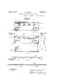
- Figure 1 isza front elevation of my-im- "proved; mount card for' artificial teeth.
- Figure 2 is a view of the blank for the mount with the retention: device attached: 2-;
- Figure 2a is an end elevation of Figure throughthe mount on the line 5, Figure' Ql,
- Figure '4 isa top' plan viewof the retention member detached;
- v Figure 5 is a" true “sectional view on the line 5-55 Figure 2;
- Figure 6 is a rear elevation of the mount.
- view of Figure 7 is a transverse sectional the mount partiallyfolded.
- igure'8 is a sectional view on. the line 8+8 Figure 1 I -PAT NTYOF w avin E iEvA s, or COiiUMBUS, oni nsslenon TO THE coLUi/iBUs DENTAL mum l
- Figure 9 is a view similar to Figure- 8 with a'toothmounted on the mount card.
- the reference letter 'A designates the blank *of my improved tooth 'mountwhich is designated to be bent upon itself on the dotted 'formed'w-itha bossC on its outer or obverse face anda ⁇ resultant depression or groove D n lts nnerorreverse face.
- the tooth retention strip 14 is formed from a suitable non-metallic material which is crimpedat predetermined intervals throughout its length to form lugs 15;
- the strip 14 is laid in the groove D in the rear face of the blank Afl'and the lugs' l5' are forcedby a suit This shape may, for want of a better term; be
- the card is now in condition to receive, for dis- Y play, artificial teeth.
- the artificial tooth 18 has a retention opening corresponding, more or less, to the cross section of the lugs and they are slid on the lugs as shown in Figure 9.
- this retention opening are thin and, if the tooth is removed from a lug of rigid type by pulling it transversely off the lug, instead of sliding it kmgitudinally off the lug, such edges are generally chipped or otherwise injured, thus seriously damaging 5 and that, therefor-git one shouldpn-ll a tooth from thecard transversely or at any other angle to the longitudinal axis of the lag, the 'sidesgot the hulhoiis head of the lngmnd the head contact will neadilyjyield with a reducson of its width soas'zto permit thetooth to be removed from the lug without any danger of spalling' or chipping the tooth.
- each lug comprising an engaging head and restricted was heoe'inbefom described, 'is substantially Usha ped, and the parts of the lug on opposite sides of its longitudinal center, therefore,'ffomi yielcl-in gwor resilient ianvs cormected :at theirouter ends by the crossed part not the head;
- the groove D and bossC serve two purnii-rst, the groove holds the strip 14., and, second, the boss C raises the level of.
- a card of sheet material having a portion thereof displaced from its plane to provide a longitudinally extending boss at one side thereof and a corresponding groove at the opposite side thereof, the walls of the boss being provided at intervals with slots, and a tooth retaining strip of non-metallic material seated in said groove and doubled at intervals to provide yielding tooth receiving and supporting lugs projecting through said slots beyond the face of the boss.
- Aicarding device for artificial teeth comprising a card of sheet material having a portion thereof displaced from its plane to "provide a longitudinally err-tending boss at one side thereof and a corresponding groove at the opposite side thereof, the walls of the boss being provided at intervals with slots,-
- the head portion beingof 4 Awarding device for artificial teeth oomprism-gym card of sheet material doubled itself toprovide a pair of corresponding leaves integrally connected at one one of said leaves having a portion displaced from its plane to provide; a longitudinally extending looss projecting beyond the outer face thereof and :a corresponding groove in the inner Tace'thereof, said boss being provided with slits at intervals, at cliplengaging the free edges of the leaves to hold the same in folded condition, and a card retaining strip of non-metallic flexible'material seated "in-the groove and doubled upon itself'to pro-' vide'tooth holding lugs projecting outwar ly through the slots in the boss beyondthe plane of said boss, the outer face of the'boss lying in aplane beyond the plane of the clip.
- lhn' a carding device for supporting land displaying artificial-teeth, a tooth :cazrd'havmg a groove extending lengthwise thereof .zandslots extending from'said gi'ooae thnough the outer ifiaoe of the card, and tooth supporting lugs of fibrous material extending from 7 said groove through said slots, and projecting beyond the outer face of the said card.
- a tooth card having a groove in said card extending longitudinally thereof, and.
Landscapes
- Health & Medical Sciences (AREA)
- Oral & Maxillofacial Surgery (AREA)
- Dentistry (AREA)
- Epidemiology (AREA)
- Life Sciences & Earth Sciences (AREA)
- Animal Behavior & Ethology (AREA)
- General Health & Medical Sciences (AREA)
- Public Health (AREA)
- Veterinary Medicine (AREA)
- Adornments (AREA)
Description
May 10, 1932. D. EiEVANS 1,857,713
' 'CARDING DE VIICE FOR ARTIFICIAL TEETH Filed Oct. 18, 1950 2 Sheets-Sheet l Cr luv-enter a Gttorneg May 10, 1932. D. E. EVANS v 1,857,713
CARDING DEVICE FOR ARTIFICIAL TEETH Filed Oct. '18, 1930 2 Sheets-Sheet 2 J g as. I
Bn'ventor Mg-M attorney vide such cardboard;
pins. v
chipping of the teeth when Patented May 10, 1932 .FACTURING COMPANY, OF COLUMBUS, OHIO, A CORPORATION CARDIN? 1 R II ALTE' TH Application filed October '18, 1930.1 Serial 1T0. 439,675.
Heretofore artificial teeth have been mounted on a card'or thelike, formed of cardboard, metal or Wood in combination with wax or other penetrable materia-Lor having a'coating of such material thereon,-the'teeth being pressed into the wax and being held thereby on the card. This method of mounting the teeth is not satisfactory in warm Weather, the Wax'beeomes too soft and easily soils :the teeth, and, coldweather, it"-be comes too hard and the teeth do notproperly adhere. g
1 Another "method employed for supporting }or mounting teeth consists of a mount of wood or metal, having split metal Another method consists of a mount having spring metal flangesor lugs. These last two methods are unsatisfactory because parties 'in removing the teeth from the mount lpull the teeth transversely of the flanges or'lugs in removing them, instead of sliding them off in the-plane of the long'axis of the-flange's or lugs which results in the metal fianges'or lugs chipping the teeth when they are thus .removedk jThe object. of my inventior'i is toprovide.
a mount or card device for' artificial teeth, which is substantially rigid inconstruction and will not easily bend or-break. H
A further object of my invention is'to proan mountrwhich will not soil the A further object of my-invention is to provide. a mount for teeth which wilLeliminate I l theteeth areremoved from the mount,
Figure 1 isza front elevation of my-im- "proved; mount card for' artificial teeth.
-:Figure 2 is a view of the blank for the mount with the retention: device attached: 2-;
Figure 2a is an end elevation of Figure throughthe mount on the line 5, Figure' Ql,
with the retention'device removed. 7
Figure '4 isa top' plan viewof the retention member detached; v Figure 5 is a" true "sectional view on the line 5-55 Figure 2;
Figure 6 is a rear elevation of the mount. view of Figure 7 is a transverse sectional the mount partiallyfolded.
igure'8 is a sectional view on. the line 8+8 Figure 1 I -PAT NTYOF w avin E iEvA s, or COiiUMBUS, oni nsslenon TO THE coLUi/iBUs DENTAL mum l Figure 9 is a view similar to Figure- 8 with a'toothmounted on the mount card. i
11 The reference letter 'A designates the blank *of my improved tooth 'mountwhich is designated to be bent upon itself on the dotted 'formed'w-itha bossC on its outer or obverse face anda} resultant depression or groove D n lts nnerorreverse face. The blank 1s pro- -1i neB,-as-clearly seen in Figures 7 8; and'9, is v vided with openings ll 'hereinafter referred to. Near the upper edge .of the blank slots 12 are p'unchedthrough the blank inthe' boss C, which slots open through1the outer face jof' theboss'and intersect the groove 1), While the-side edges of the blank near the bottom are notched-asatl3'i- The tooth retention strip 14 is formed from a suitable non-metallic material which is crimpedat predetermined intervals throughout its length to form lugs 15; The strip 14 is laid in the groove D in the rear face of the blank Afl'and the lugs' l5' are forcedby a suit This shape may, for want of a better term; be
contraction under pressure. After the lugs are posltloned 1n the slots as shown-in Figure 5,tl1eblank*is then folded on the line B and able instrumentthro-ughathe slots 12, as clearly--'shownrin Figurer5'. It willbe notedj as shown in Figure 5, thattheselugs laafter being passed throughthe s1ots12,-assume the form ofa head, amore or less bulbous shape, carried by arestricted neck or stem 16";
the two halves of the blank brought into contact and are held in that position by a cap or clamp 17 of any suitable material. The card is now in condition to receive, for dis- Y play, artificial teeth. The artificial tooth 18 has a retention opening corresponding, more or less, to the cross section of the lugs and they are slid on the lugs as shown in Figure 9. The marginal edges of this retention opening are thin and, if the tooth is removed from a lug of rigid type by pulling it transversely off the lug, instead of sliding it kmgitudinally off the lug, such edges are generally chipped or otherwise injured, thus seriously damaging 5 and that, therefor-git one shouldpn-ll a tooth from thecard transversely or at any other angle to the longitudinal axis of the lag, the 'sidesgot the hulhoiis head of the lngmnd the head contact will neadilyjyield with a reducson of its width soas'zto permit thetooth to be removed from the lug without any danger of spalling' or chipping the tooth. As shown, each lug, comprising an engaging head and restricted was heoe'inbefom described, 'is substantially Usha ped, and the parts of the lug on opposite sides of its longitudinal center, therefore,'ffomi yielcl-in gwor resilient ianvs cormected :at theirouter ends by the crossed part not the head; By forming the lug strip and each lag of a yielding non anetallic naterial, .a tooth fitted on 'the lug, if removed by pulling :it transversely off the lug,
instead of sliding it longitudinally of the lug,
will be damaged, as the iaws of I-the lug will yield under pressure and thus contract the head, vallloivingthe tooth to be released without chipping or otherwise injuring the ana-rginal edges of its retention sllot. As far %as I .lcnow I am the first to provide such a yielding tooth supporting lug.
The thickness of he lug strip Mspaces the 1' W0 folded portionsot 't'h-e rhl-an-lr just :suliici cut to penmit o-i? the ready insertion fairdiwithdrawval or the imdicia oari'l :19;and thenotches 1-3 "expose the'ends of the card'19 justxeirough to enable one to grasp its ends "forremoval.
The groove D and bossC serve two purnii-rst, the groove holds the strip 14., and, second, the boss C raises the level of. the
F supporting surfaces of the lugs, ie., projects such surf-aces outwardly,beyond the plane of the card to such .adegnee that the tooth will pass orer the metal cap 151' without friction.
What I'claimis: f 1. A carding device for artificial teeth jaws. c
' from! in cross-section.
comprising a card of sheet material having a portion thereof displaced from its plane to provide a longitudinally extending boss at one side thereof and a corresponding groove at the opposite side thereof, the walls of the boss being provided at intervals with slots, and a tooth retaining strip of non-metallic material seated in said groove and doubled at intervals to provide yielding tooth receiving and supporting lugs projecting through said slots beyond the face of the boss.
2. Aicarding device for artificial teeth comprising a card of sheet material having a portion thereof displaced from its plane to "provide a longitudinally err-tending boss at one side thereof and a corresponding groove at the opposite side thereof, the walls of the boss being provided at intervals with slots,-
and a tooth retaining strip of non-metallic material seated in said groove and doubled at intervals to provide yielding tooth receiving and supporting lugs projecting through mid slots, beyond the face of the boss, each comprising a stem portion forming yielding'jaws and a lhe'adportion connecting said X 3; A carding device for artificial teeth prisingia card of sheet material having a por- 7 tion thereof displaced from its plane to proyide a longitudinally extending boss at one thereof and a corresponding groove at the opposite side thereof, the walls of; the
,hoss being provided at intervals with slots,
and awtooth retaining strip of non-metallic material, seated said vgroove and doubled at intervals to provide yielding tooth receiving and supporting hugs projecting flirouglh said slots beyond the face-of the boss, each el-ug aoomspirising a stem portion forming yielding jaws and a head-portion :ing
said-jaws, the head portion beingof 4 Awarding device for artificial teeth oomprism-gym card of sheet material doubled itself toprovide a pair of corresponding leaves integrally connected at one one of said leaves having a portion displaced from its plane to provide; a longitudinally extending looss projecting beyond the outer face thereof and :a corresponding groove in the inner Tace'thereof, said boss being provided with slits at intervals, at cliplengaging the free edges of the leaves to hold the same in folded condition, and a card retaining strip of non-metallic flexible'material seated "in-the groove and doubled upon itself'to pro-' vide'tooth holding lugs projecting outwar ly through the slots in the boss beyondthe plane of said boss, the outer face of the'boss lying in aplane beyond the plane of the clip.
. 5, lhn' a carding device for supporting land displaying artificial-teeth, a tooth :cazrd'havmg a groove extending lengthwise thereof .zandslots extending from'said gi'ooae thnough the outer ifiaoe of the card, and tooth supporting lugs of fibrous material extending from 7 said groove through said slots, and projecting beyond the outer face of the said card. 6. In a carding device for supporting and displaying artificial teeth, a tooth card having a groove in said card extending longitudinally thereof, and. slots extending from said groove through the outer face of said card, a lug strip of cardboard or like fibrous 10 material seated in said groove, and tooth su porting lugs formed by erimpingsaid strip and projected through said slots and beyond the outer face of said card.
In testimony whereof I aifix my signature. DAVID E. EVANS.
Priority Applications (1)
| Application Number | Priority Date | Filing Date | Title |
|---|---|---|---|
| US489675A US1857713A (en) | 1930-10-18 | 1930-10-18 | Carding device for artificial teeth |
Applications Claiming Priority (1)
| Application Number | Priority Date | Filing Date | Title |
|---|---|---|---|
| US489675A US1857713A (en) | 1930-10-18 | 1930-10-18 | Carding device for artificial teeth |
Publications (1)
| Publication Number | Publication Date |
|---|---|
| US1857713A true US1857713A (en) | 1932-05-10 |
Family
ID=23944815
Family Applications (1)
| Application Number | Title | Priority Date | Filing Date |
|---|---|---|---|
| US489675A Expired - Lifetime US1857713A (en) | 1930-10-18 | 1930-10-18 | Carding device for artificial teeth |
Country Status (1)
| Country | Link |
|---|---|
| US (1) | US1857713A (en) |
-
1930
- 1930-10-18 US US489675A patent/US1857713A/en not_active Expired - Lifetime
Similar Documents
| Publication | Publication Date | Title |
|---|---|---|
| US4376628A (en) | Device for treating teeth | |
| JPH02214885A (en) | Artificial tooth mounting apparatus | |
| US1857713A (en) | Carding device for artificial teeth | |
| DE633468C (en) | Designation mark for insulated electrical lines | |
| US3015888A (en) | Artificial tooth structure and plate therefor | |
| US11136799B2 (en) | Door stop | |
| US4509268A (en) | Dental curet sharpening guide | |
| US4642050A (en) | Alignment cap for mounting artificial teeth on working models | |
| WO2008017089A1 (en) | Device for exact and reproducible transfer of dental retention elements | |
| US2269087A (en) | Plant marker | |
| US2469210A (en) | Card support and display | |
| US1857714A (en) | Carding device for artificial teeth | |
| US2352545A (en) | Impression tray | |
| DE3831919A1 (en) | Plate for holding artificial teeth | |
| US3148767A (en) | Brush holder | |
| US1865112A (en) | Hook and eye holder | |
| US2686379A (en) | Sealing means | |
| US1422880A (en) | Mechanical connector | |
| DE806432C (en) | Holding device for small letter files | |
| US1283100A (en) | Picture-frame. | |
| US1878221A (en) | Lug strap holder | |
| US1078829A (en) | Die for forming dental backings. | |
| US1390353A (en) | Artificial tooth | |
| US1700943A (en) | Window advertising display | |
| US1696016A (en) | Index |