US1857564A - Floor surfacing machine - Google Patents
Floor surfacing machine Download PDFInfo
- Publication number
- US1857564A US1857564A US278011A US27801128A US1857564A US 1857564 A US1857564 A US 1857564A US 278011 A US278011 A US 278011A US 27801128 A US27801128 A US 27801128A US 1857564 A US1857564 A US 1857564A
- Authority
- US
- United States
- Prior art keywords
- bar
- machine
- shaft
- surfacing
- floor
- Prior art date
- Legal status (The legal status is an assumption and is not a legal conclusion. Google has not performed a legal analysis and makes no representation as to the accuracy of the status listed.)
- Expired - Lifetime
Links
- 230000033001 locomotion Effects 0.000 description 20
- 230000007246 mechanism Effects 0.000 description 16
- 230000000694 effects Effects 0.000 description 5
- 229920001800 Shellac Polymers 0.000 description 2
- 230000015572 biosynthetic process Effects 0.000 description 2
- 230000003028 elevating effect Effects 0.000 description 2
- ZLGIYFNHBLSMPS-ATJNOEHPSA-N shellac Chemical compound OCCCCCC(O)C(O)CCCCCCCC(O)=O.C1C23[C@H](C(O)=O)CCC2[C@](C)(CO)[C@@H]1C(C(O)=O)=C[C@@H]3O ZLGIYFNHBLSMPS-ATJNOEHPSA-N 0.000 description 2
- 229940113147 shellac Drugs 0.000 description 2
- 235000013874 shellac Nutrition 0.000 description 2
- 239000004208 shellac Substances 0.000 description 2
- 239000002966 varnish Substances 0.000 description 2
- RUPBZQFQVRMKDG-UHFFFAOYSA-M Didecyldimethylammonium chloride Chemical compound [Cl-].CCCCCCCCCC[N+](C)(C)CCCCCCCCCC RUPBZQFQVRMKDG-UHFFFAOYSA-M 0.000 description 1
- 244000137852 Petrea volubilis Species 0.000 description 1
- 208000036366 Sensation of pressure Diseases 0.000 description 1
- 239000011248 coating agent Substances 0.000 description 1
- 238000000576 coating method Methods 0.000 description 1
- 238000010276 construction Methods 0.000 description 1
- 230000009977 dual effect Effects 0.000 description 1
- 238000010438 heat treatment Methods 0.000 description 1
- 239000000463 material Substances 0.000 description 1
- 230000007935 neutral effect Effects 0.000 description 1
- 230000002093 peripheral effect Effects 0.000 description 1
- 230000008092 positive effect Effects 0.000 description 1
- 230000002787 reinforcement Effects 0.000 description 1
- 239000011435 rock Substances 0.000 description 1
- 238000006748 scratching Methods 0.000 description 1
- 230000002393 scratching effect Effects 0.000 description 1
Images


Classifications
-
- B—PERFORMING OPERATIONS; TRANSPORTING
- B24—GRINDING; POLISHING
- B24B—MACHINES, DEVICES, OR PROCESSES FOR GRINDING OR POLISHING; DRESSING OR CONDITIONING OF ABRADING SURFACES; FEEDING OF GRINDING, POLISHING, OR LAPPING AGENTS
- B24B7/00—Machines or devices designed for grinding plane surfaces on work, including polishing plane glass surfaces; Accessories therefor
- B24B7/10—Single-purpose machines or devices
- B24B7/18—Single-purpose machines or devices for grinding floorings, walls, ceilings or the like
Definitions
- This invention relates to floor surfacing machinery'and provides anarticle of thisnature which is effective and rapid in operation anclwhich resultsJin a finished surface free fromscratchesand spotssince all the coating, such as varnish and shellac, is entirely r moved from eld fioors.
- the invention provides a machine which, when adj usted', requires-but little attention. as it is automatic in reversing whenreaching the end of'its travel in each direction.
- Fhe invention further provides means for lifting the a tractor and surfacing mechanism clear ofthe floor when the side of the room hasbeen reached and maintaining such parts in elevated position until adjustment has been made to adapt the'machineto a continuance of thework.
- Theinvention provides surfacing mechanism operating at a right angle to the path of travelof themach-ine and simultaneously receiving a reciprocator y movement to -obviate ghe formation of scratches in the finished surace.
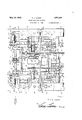
- Figure I is a top plan View ofthe floor surfacing'machine embodyingthe invention, the npper run of a surfacing belt beingv broken away.
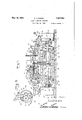
- Figure '2 is a side View of the' machine partly in section, showing itin position upon a floor.
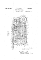
- Figure 3 is a. view similar to Figure 2, of thereverse side of the machine.
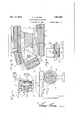
- FIG. 5 is a fragmentary sectionalfview illustrating in detail the tractormechanism
- FIG. 1 is an enlarged detail sectional 1928.
- FIG. 7 is an enlarged fragmentary sectional view of a portion oft-he elevating mechanism forlifting the tractor and surfacing unechanism.
- Figure 8i is a fragmentary sectional view of the surfacing mechanism:
- Figure 9 is a detail sectional view'on the line 9-9'0f Figure 8, looking in the direction ofthea-rrows.
- Figure 10 isa top plan viewof the means foradjusting the surfacing heltif
- a Figure 11 is aside view y 1 FigureIQ'is an endvi'ew ofthe same. 5
- the numeral 1 denote's' a platform.-which may be of any determinate structure'depending upon the design and capacity ofthe machine.
- the motorr; shifting and clutchv mechanisms aremounted upon the platform and the propelling'and surfacing mechanisms are disposed'approximately below; the platform,*pow'er beingtransmittedthereto from v the motor by suitablegearing and connections.
- a side bar-or frame 2- is located at g each side of the machine some distance-below so the-platform 1.
- Ties- 3 ' connect theframes 2 and support struts' lwhich aresecuredthereto, a nd to-thepla'tform 1L
- the frames 2 are p of like'construction and each has itsends of' circular outline.
- Parallel grooves or chans5 nels 5 areformed'in thetopsybottomsj and ends of each of theframes 2 and receive peripheral portions of rollers 6';
- endless chains one for each groove or channel 5 of each ofthe frames 2.
- Each of these endless chains comprises links 11' which are connected by pins upon 7 which the rollersdare mounted; Blocks 12 are fastenedtd the outer sides ofthe-links l1 and 'constituteshoes whichmake con-tact with the surface of the floor to be dressed or leveled. To prevent slipping and insure positive traction the outer surfaces of the blocks or shoes 12 are roughened in any convenient manner, as by having sand paper 1.3 applied thereto.
- the flat faces of the pulleys 8 correspond in length to blocks 14 which are secured to the inner sides of the links 11 and make contact with the faces of the pulleys when traveling around the same.
- the shafts 9,0ne at each end of theframe 2 are journaled at their ends in the said frames. One of the shafts is positively driven through power applained more fully hereinafter.
- a suitable'motor 17 is mounted upon the platform 1 and power is taken therefrom to operate the working parts. It is preferred toutilize an electric motor, and its shaft is suitably geared to a main shaft 18 which is disposed intermediate the endless tractors and parallel therewith. Sprocket wheels 19 and 20 are fast to the shaft 18 so as to rotate therewith.
- Bevel gears 21 and 22 are mounted loosely on the shaft 18 and each is provided upon its inner side with a half clutch to cooperate with a clutch member23 splined to the shaft 18 and shiftableby means of a lever 24, these gears and clutch members being located between the sprockets 20 and the end of the machine.
- a bevel gear 25 is in mesh with the bevel gears 21 and 22, and is fast to a transverse shaft 26.
- a sprocket gear 27 fast to the shaft 26 is connected by means of a sprocket chain 28 with the sprocket gear 10 fast to the shaft 9. In this manner the endless tractors are driven for propelling the machine over the surface to be dressed.
- a shaft 29 is mounted in the bracket 16 at one side of the machine and extends across the machine with its ends projecting beyond the ends of the frames 2.
- a sprocket gear 30 is fast to the shaft 29 and asprocket chain 31 connects the sprocket gear 30 with a sprocket gear 32 fast to a short shaft 33 mounted in'the brackets 15.
- a sprocket chain 34 connects the sprocket gear 19 with. a sprocket gear 35 fast to the shaft 33. In this manner power is transmitted from the main shaft 18 to the shaft 29.
- a short shaft 36 is located at the opposite side of the machine'and is mounted in the which gear is operatively connected by a sprocket chain 410 with the sprocket wheel 37.
- a spur gear 41 at each end of the shaft 39 is in mesh with a spur gear 42 mounted in the lower end of a lever 43.
- Small wheels or rollers 44 are disposed at the sides of the spur gear 42 and are of slightly larger diameter to prevent contact of the spur gears with the surface of the floor when the levers are rocked to cause the rollers to bear thereon.
- Levers 45 similar to the levers 43 are located at the opposite end' of the'machi'ne and support small wheels 46 corresponding to the rollers 44.
- Bars 47 form parts of connecting means between the levers 43 and 45 and each bar is pivotally con nected at one end to the respective lever 43.
- a bar 48 pivoted intermediate its ends has its upper end connected to the bar 47 and its lower end connected by means of a link 49 to the lever 45. Movement of the bar 47 in one direction effects a simultaneous movement of the levers 43 and 45 to lower the respective wheels 44 and 46 so as to elevate the machine and permit it to travel sidewise on said wheels. Movement of the bar 47 in the o posite direction elevates the wheels 44 an 46 to permit a lowering of the machine to bring the surfacing and tractor mechanisms in con-' tact with the surface to be leveled andfinished.
- a shaft 50 mounted in suitable bearings provided uponthe platform 1 has the bars 48 fast thereto with the result that the four levers 43 and 45 receive a simultaneous movement.
- a transverse bar 55 slidable in bearings providedtherefor at the upper ends of standards or posts on the platform is provided upon its top side with ratchet teeth 56 to be engaged by the pawl 52 and upon its lower side with cog teeth 57. This bar 55 projects beyond the side ofthe machine, as shown in Figure 4, and in actual practice will project a distance equal to the width of the machine.
- a gear wheel 58 loose on the shaft 18 has its teeth in mesh with the cog teeth 57 of the bar 55, and is hollow to receive a coil spring 59 which is fast at one end to any convenient fixed point and at its opposite end to the gear wheel.
- This gear wheel is provided upon one side with a half clutch to coact with a clutch member 60-splined to the'shaft 18.
- a lever 61 coacts with the clutch member 60 to effect engagement thereof with the gear wheel
- An arm 51 projects upwardly 58'-3Ild .0311$61tl16i gear wheelto rotate with the shaft 18:. in onedirection for tensioning thespring, 59, and to release the gear wheel to admit; of a reverse movement thereof by the actioniof the spring 59 after the; gear wheel hasbeen released.
- a bar ,coextensive in length with the sec'- tional bar and slidably mounted in-the same bearings 62 is yieldably connected to the lever 24 cooperating with the clutch member 23.
- the bar 65 is longitudinally slotted at 165 to receive a block connected to the lever 24 and springs at opposite si'desof the block as; shown in Fig. 2, whereby to insure positive action of the clutch-member 23 when, in
- the bar 65 is moved manually longitudinally in either direction to clutch one or the other of the bevel gears 21 and 22 to the shaft .18 according to the de sired direction of travel of the machine.
- a trip 66 is carried by the bar 55 and is adjustably connected to a side thereof in alinement with and. outwardly from the pawl 53!
- the opposing; ends of the. trip 66 and pawl 53 are correspondingly bev l d ith the result that whenthe beveled end of the trip rides upon the beveled end of the pawl the latter is rocked and, disengaged from the catch 54.
- the lifter 67 consists of a fiat spring and is backedby' a reinforcement which sustains the initial stress incident to the pawl riding upon the lifterwhen clearing the tooth 56 with which it is in engagement.
- the pawl 53 is set slightly in advance of the pawl 52 and when in engagement with the catch 54 relieves the pawl 52 of all stress and admits of the pawl 52 being held clear of theteeth 56 by the spring-action of the lifter 67.
- a stop 68 mounted upon the bar 55 is adapted to engage theupper end of the lever 61 and move it and the clutch member 60 to release the gear wheel 58'When the bar 55 reverses its movement.
- Agroove'or channel is formed in thetop side of the bar. 55,. and the bottom wallthereof is formed with teeth:70.
- a bar: 71 is; loosely tted. Within this groove or channel and its.
- the bar 71 normally has its top side'in the plane of the teeth 56 of the bar 55, and is. slidable in the bearings in whichithe bar 55 is mounted.
- the bar 71 projects beyond the ends of the bar 55 andis provided at one; endwith astop 72 and at its opposite :endiwith a stop 73.
- An, open coil? spring 74' mounted upon the projecting end of the bar 71 and confined between the mounted. This constitutes a temporary lock ing means to secure the bar55 until: such time as the gear wheel58isi clutched, to the shaft 18 to impart movementto thebar55, whereupon the bar 71 returns to 'normal'position' under the action of, the spring 74.
- This latter movement of the bar-71 is limited'by the stop 7 2. at the end thereof remote from the stop or head 73.
- Pulleys 75 and 76 are located at opposite ends of the machine and at opposite-sides thereof and support endless belts 77 which are coated upon their outer surfaces with an abrading material of a nature'to eifect leveling and finishing of a. floorto be surfaced;
- the pulleys 7 5 and 76 at the respective ends of the machine are in" line.
- The, pulleys 75 are fast to opposite "ends of the'shaft 29 and are positively driven.
- the pulleys-7 6 are loosely mounted uponshort shafts 78 whichare' mounted in brackets 79 pivoted upon axles 80 mounted in; brackets 81'.
- the brackets 81 forma ofthe main frame and the axles 80' have their outer ends suitably shaped'to be pivoted to the outer endsxthereof as indicated at 82.
- Thea-Xles 80 and brackets 79. are" adjusted angularly by means of set screws 83 which are swiveled in the frame or the bracket 81 and are threadedthrough theinner ends ofthe'respective axles 80 so as to turn the axles and-thebrackets 79 about the pivot 82 and also servetohold the axles in therequiredadjusted position.
- the brackets 7 9 being mounted upon the axles 80 move therewith andin consequence the shafts. 78 may be: angularly adjusted to parallel the shaft 29. whereby to bring the outer, elements of the pulleys75'and 7.6: into .2
- the brackets 79 areadapted to swing at their lower ends to move the shafts 78 towards and awayfrom the shaft 29, whereby to properly tension the endless belt 77
- Set screws84s are threadedthrough the lower eX- tremity of the respective brackets 79 and bearing against the side of the respectively adjacent brackets 81 for adjusting the lower ends of the brackets 79 toward or from the shaft 29 and maintaining them in the required adjusted position.
- the brackets 79 have a two-fold adjustment, the one about the pivot 82 and 3 the other aboutthe axles 80, and this admits of the pulleys 76 having a corresponding dual adjustment.
- 'Arms 85 project from the respective ties?
- Short cross bars 91 are secured to the bars 86 and 87 and project inwardly therefrom and are pivotally connected at their inner ends as shown most clearly in Figure 8 of the drawings.
- the cross bars 91 and links 90 maintain the pres sure bars 87 in given position and relieve the pins 89 and springs 88 of any tendency to bind.
- These feet 92 automatically turn on their pivots to swing out of the way and'assume a trailing position, when the machine is moved in either direction, to permit the belts to meet the floor surface.
- the abrasive or surfacing belts 77 receive a simultaneous lateral movement which prevents the formation of scratches in the finished surface. Thisis effected by a lateral movement of the pulleys 75 and 76, the pulleys 75 being fast to the ends of the shaft 29 and moving therewith while pulleys 76 are loose on the shaft 78 and move thereon.
- a shaft 93 paralleling the belt 77 is mounted in bearings connected with the platform 1 and extends approximately from one side of the machine to the opposite side.
- An arm 94 projects upwardly from the shaft'93 and terminates in a fork which coacts with a cam 95 fast to the shaft 18.
- the cam 95 consists of a wheel formed in its periphery witha cam groove of a shape to impart from the respective shafts, the arrangement being such as to cause the shafts 93 to rock in unison;
- Similar arms 102 depend from the outer ends of the shafts 93 and98 and their lower ends are connected. by means of links 103 with the hubs of pulleys 76. In this manner a simultaneous movement is imparted to the pulleys 76 on their respective shafts 78.
- the depending arms 96 and 102 are of equal length and in consequence the surfacing belts 77 and their supporting pulleys 75 and 76 receive a like lateral movement which is at a right angle to the path of travel of the belts.
- the belts 77 are driven at a speed to prevent the heating of varnish and shellac surfaces and insure a removal of the old finish without gumming and choking the belts and impairin their efficiency.
- the belts travel in the same direction at a uniform rate of speed and at the same time have a lateral reciprocatory. movement imparted thereto which pre vents scratching and insures a smooth finish to the floor or other surface under treatment.
- the machine advances in a path at a right angle to the travel of the finishing belt 77. lVhen the machine reaches the limit of itstravel in each direction it is automatically reversedby'the means and in the manner herein specified.
- the machine In use, the machine is placed in one corner of a room, the motor started and the clutch 28 set to cause the tractors and surfacing belts to operate. The machine will then travel along one wall to the opposite side of the room, then along the side adistance equal to the width of the machine, and then back b0 the starting wall, continuing to follow a zigzag path until the entire floor has been treated. As shown in Figures 1 and 98 and 2, the clutch sleeve 23 is engaged with the gear 21 and the tractors are consequently being driven in such direction that the machine will travel to the left in Figure 2.
- the bar will come in contact therewith and will be pushed inward, thereby disengaging the gear 21 and engaging the gear 22 to effect reverse travel of themachine.
- the bar 64 is pushed inwardly simultaneously with the bar 65, thereby rocking the lever 61 and closing the clutch 60 which is always open when the machine is traveling on the trac-- tors.
- the clutch 60 is closed, the wheel 58 will be made active and will draw the bar 55 inward, rocking the arm 51 through the pawl 52 and transmitting the movement through the bars 47 and links 49 tothe levers 48 and 45 which are thereupon rocked.
- a floor surfacing machine comprising a frame, a power driven shaft thereon, tractor means mounted on the frame and operatively connected with the power shaft for propelling the machine, means mounted on the frame and operable by impact with a fixed object to reverse the direction of travel of the tractor means, and surfacing mechanism carried by the frame and deriving move ment from the power driven shaft.
- a surfacing machine comprising a frame, a power driven shaft thereon, tractor means carried by the frame and operated by said shaft for propelling the machine over the surface, cooperating reversing gears and a clutch interposed between the tractor means and the power driven shaft, a bar slidably mounted on the frame and projecting beyoncl the same, (connections between said bar and the clutch whereby upon aimpactzofthe end of the bar :a'gainst ta ifi'xed object the direction of travel will be reversed, andsurfacing mechanism icarried :by ithe frame and deriving power fnom'the ':positi-vel-y zrlrivenshaft and operating in :adirection transverse to the direction of travel of the :tractor means.
- a floor surfacingmachine comprisinga frame, tractor and -.su-rfacing mechanisms mounted thereon, liftingzelementgimeansfor lowering "the lifting elements into contact with the :surface rto elevate the traetor and surfacing .mecha nisms, locking means for..se-
- a frame, tractor and surfacing 1 mechanisms thereon lifting elements, a bar for operating the lifting elements, a pawl carried by the operating bar and adapted to coact with a clutch for holding the lifting elements in operative position, and a spring actuated member operated by the bar to tension the spring which, when released, returns said bar to a given position.
- afioor surfacing machine a frame, tractor and surfacing mechanisms thereon, lifting elements, a pivoted bar for operating mounted upon the pivoted her, one of the pawls being engageable with the toothed" to return it to normal'posit-ion after the parts have been. released. 7 r
- a floor surfacing machine the come binationof a frame, tractor and surfacing mechanisms thereon, lifting elements, a pivoted bar connected with the lifting elements to effect operation thereof, pawls mounted upon the pivoted bar, a toothed bar coacting with one of said pawls to move the lifting elements into operative position, a catch for engaging the other pawl to hold the lifting elements in loweredjposition, a spring gear wheel tensioned by movement of the toothed bar in one direction to return it to normal position when released, a lifter for disengaging the pawl from the toothed bar, and a trip carried'by the toothedbar for-disengaging the pawl from the said catch.
- a floor surfacing machine the cornbination of a frame, tractor and surfacing mechanisms thereon, lifting elements, a pivoted bar connected with the lifting elements to effect operation thereof, pawls mounted upon the pivoted bar, a toothed bar coacting with one of said pawls to move the lifting elements into operative position, a catch for engaging the other pawl to hold the lifting elements in lowered position a spring gear wheel tensioned by movement of the toothed bar in one direction to return it to normal position when released, a lifter for disengaging the awl from the toothed bar, and a trlpearriedhy the toothed bar for disengaging the pawl from thesaid catch, a bar mounted upon the toothedbar, coacting teeth between the two bars, a spring normally urging the bar in one direction'and a stop for limiting the movement of the said bar.
Landscapes
- Engineering & Computer Science (AREA)
- Mechanical Engineering (AREA)
- Soil Working Implements (AREA)
Description
May 10, 19 2. OLSQN 1,857,564
FLOOR SURFACING MACHINE Filed May 15. 1928 6 Sheets-Sheet l H I] n ue-m fez El. El 15 EITL May 10, 1932.
c. J. OLSON FLOOR SURFACING MACHINE I Filed May 15. 1928 6 Sheets-Sheet 2 m WWW J m-ue m tom EWIEHEIUTL Gwynne/15 J 4 May 10, 1932. c, J; QLSQN 1,857,564
FLOOR S-IURFACING' MACHINE Filed May 15. 1928 6 Sheets-Sheet. 3
' Gbtomma l May 10, 1-932. c. J. OLSON: 1 8 7,
FLOOR SURFACING MACHINE Filed May '15. 1928 e Sheets-Sheet 4 May 10, 1932.
c. .1. OLSON FLOOR SURFACING MACHINE Filed May 15; 1928 6 Sheets-Sheet 5 ghrumll'oz g EJ. [115 can y 1932. c. J. OLSON 1,857,564
FLOOR SURFAG I NG MACHINE Filed May 15. 1928 6 Sheets-Sheet 6 figjlll Patented May 10, 1932 UNITED STA I ermnnnsa. OLSON, or mnsxneonmicnieen. I
' FLoon snnrnome mecnlnin Application filed May 15,
This invention relates to floor surfacing machinery'and provides anarticle of thisnature which is effective and rapid in operation anclwhich resultsJin a finished surface free fromscratchesand spotssince all the coating, such as varnish and shellac, is entirely r moved from eld fioors. p
The invention provides a machine which, when adj usted', requires-but little attention. as it is automatic in reversing whenreaching the end of'its travel in each direction.
Fhe invention further provides means for lifting the a tractor and surfacing mechanism clear ofthe floor when the side of the room hasbeen reached and maintaining such parts in elevated position until adjustment has been made to adapt the'machineto a continuance of thework. r
Theinvention provides surfacing mechanism operating at a right angle to the path of travelof themach-ine and simultaneously receiving a reciprocator y movement to -obviate ghe formation of scratches in the finished surace.
While the drawings illustrate a preferred embodiment of" the invention, it is to be 1mderstooclthat' in adapting the 'meansto meet specific needs and requirements, the design may be varied and changes'in theminor details of constructionmay be resorted towith in the scope of the inventionas claimed, with-v out departing from'the' spirit thereof. i
For a full understandingofthe invention and the merits thereof, reference is to be had to the following description and" the drawings hereto attached, in which,-- I
Figure Iis a top plan View ofthe floor surfacing'machine embodyingthe invention, the npper run of a surfacing belt beingv broken away.
Figure '2 is a side View of the' machine partly in section, showing itin position upon a floor.
Figure 3 is a. view similar toFigure 2, of thereverse side of the machine.
Figure leis anend view of the machine.
Figure 5 is a fragmentary sectionalfview illustrating in detail the tractormechanism;
Figure 6 is an enlarged detail sectional 1928. Serial no; 278,011.
viewof an end'portion of the tractor m'cha ll'lSIfl. I Figure .7 is an enlarged fragmentary sectional view of a portion oft-he elevating mechanism forlifting the tractor and surfacing unechanism. V r
Figure 8i's a fragmentary sectional view of the surfacing mechanism: Figure 9 is a detail sectional view'on the line 9-9'0f Figure 8, looking in the direction ofthea-rrows.
' Figure 10 isa top plan viewof the means foradjusting the surfacing heltif A Figure 11 is aside view y 1 FigureIQ'is an endvi'ew ofthe same. 5
7 Corresponding and like partsare. referred to in the following description and designated in the several views of the drawings by likereferencecharacters.
' The numeral 1 denote's' a platform.-which may be of any determinate structure'depending upon the design and capacity ofthe machine. The motorr; shifting and clutchv mechanisms aremounted upon the platform and the propelling'and surfacing mechanisms are disposed'approximately below; the platform,*pow'er beingtransmittedthereto from v the motor by suitablegearing and connections. A side bar-or frame 2- is located at g each side of the machine some distance-below so the-platform 1. Ties- 3 'connect theframes 2 and support struts' lwhich aresecuredthereto, a nd to-thepla'tform 1L The frames 2 are p of like'construction and each has itsends of' circular outline. Parallel grooves or chans5 nels 5 areformed'in thetopsybottomsj and ends of each of theframes 2 and receive peripheral portions of rollers 6'; A mortise Tisformed in eachendofthe framesQzintermediate the grooves-or channelsf5' to'receive a polygonal pulley 8 oftriangular outline which is keyed to a shaft 9 and-upon one shaft 9'is mounted a-gear element 10. f
There; are provided endless chains, one for each groove or channel 5 of each ofthe frames 2. Each of these endless chainscomprises links 11' which are connected by pins upon 7 which the rollersdare mounted; Blocks 12 are fastenedtd the outer sides ofthe-links l1 and 'constituteshoes whichmake con-tact with the surface of the floor to be dressed or leveled. To prevent slipping and insure positive traction the outer surfaces of the blocks or shoes 12 are roughened in any convenient manner, as by having sand paper 1.3 applied thereto. The flat faces of the pulleys 8 correspond in length to blocks 14 which are secured to the inner sides of the links 11 and make contact with the faces of the pulleys when traveling around the same. The shafts 9,0ne at each end of theframe 2, are journaled at their ends in the said frames. One of the shafts is positively driven through power applained more fully hereinafter.
A suitable'motor 17 is mounted upon the platform 1 and power is taken therefrom to operate the working parts. It is preferred toutilize an electric motor, and its shaft is suitably geared to a main shaft 18 which is disposed intermediate the endless tractors and parallel therewith. Sprocket wheels 19 and 20 are fast to the shaft 18 so as to rotate therewith. Bevel gears 21 and 22 are mounted loosely on the shaft 18 and each is provided upon its inner side with a half clutch to cooperate with a clutch member23 splined to the shaft 18 and shiftableby means of a lever 24, these gears and clutch members being located between the sprockets 20 and the end of the machine. A bevel gear 25 is in mesh with the bevel gears 21 and 22, and is fast to a transverse shaft 26. A sprocket gear 27 fast to the shaft 26 is connected by means of a sprocket chain 28 with the sprocket gear 10 fast to the shaft 9. In this manner the endless tractors are driven for propelling the machine over the surface to be dressed. y A shaft 29 is mounted in the bracket 16 at one side of the machine and extends across the machine with its ends projecting beyond the ends of the frames 2. A sprocket gear 30 is fast to the shaft 29 and asprocket chain 31 connects the sprocket gear 30 with a sprocket gear 32 fast to a short shaft 33 mounted in'the brackets 15. V
A sprocket chain 34 connects the sprocket gear 19 with. a sprocket gear 35 fast to the shaft 33. In this manner power is transmitted from the main shaft 18 to the shaft 29. A short shaft 36 is located at the opposite side of the machine'and is mounted in the which gear is operatively connected by a sprocket chain 410 with the sprocket wheel 37. Through the instrumentalities just described motion is imparted to the shaft 39 from the main shaft 18. A spur gear 41 at each end of the shaft 39 is in mesh with a spur gear 42 mounted in the lower end of a lever 43. Small wheels or rollers 44 are disposed at the sides of the spur gear 42 and are of slightly larger diameter to prevent contact of the spur gears with the surface of the floor when the levers are rocked to cause the rollers to bear thereon. Levers 45 similar to the levers 43 are located at the opposite end' of the'machi'ne and support small wheels 46 corresponding to the rollers 44. Bars 47 form parts of connecting means between the levers 43 and 45 and each bar is pivotally con nected at one end to the respective lever 43.
A bar 48 pivoted intermediate its ends has its upper end connected to the bar 47 and its lower end connected by means of a link 49 to the lever 45. Movement of the bar 47 in one direction effects a simultaneous movement of the levers 43 and 45 to lower the respective wheels 44 and 46 so as to elevate the machine and permit it to travel sidewise on said wheels. Movement of the bar 47 in the o posite direction elevates the wheels 44 an 46 to permit a lowering of the machine to bring the surfacing and tractor mechanisms in con-' tact with the surface to be leveled andfinished. A shaft 50 mounted in suitable bearings provided uponthe platform 1 has the bars 48 fast thereto with the result that the four levers 43 and 45 receive a simultaneous movement. from the shaft 50 and'is provided at its upper end with pawls 52 and 53 which are pivotally connected thereto on its opposite sides. A catch 54, which is supported in a fixed position above the platform, is adapted to be engaged by andcoact with the pawl 53 to hold the arm 51 in the adjusted position when the wheels 44 and 46, are lowered to elevate the 'machine. A transverse bar 55 slidable in bearings providedtherefor at the upper ends of standards or posts on the platform is provided upon its top side with ratchet teeth 56 to be engaged by the pawl 52 and upon its lower side with cog teeth 57. This bar 55 projects beyond the side ofthe machine, as shown in Figure 4, and in actual practice will project a distance equal to the width of the machine.
A gear wheel 58 loose on the shaft 18 has its teeth in mesh with the cog teeth 57 of the bar 55, and is hollow to receive a coil spring 59 which is fast at one end to any convenient fixed point and at its opposite end to the gear wheel. This gear wheel is provided upon one side with a half clutch to coact with a clutch member 60-splined to the'shaft 18. A lever 61 coacts with the clutch member 60 to effect engagement thereof with the gear wheel An arm 51 projects upwardly 58'-3Ild .0311$61tl16i gear wheelto rotate with the shaft 18:. in onedirection for tensioning thespring, 59, and to release the gear wheel to admit; of a reverse movement thereof by the actioniof the spring 59 after the; gear wheel hasbeen released. The lever 6lis fulcrumed a. short distance from. its lowerxend andis pivotally connected to a bar which-is slidably mounted in bearings 62 and. includes sections 63 and. 64 the inner end of the section 63 being'ofl'set and pivotally connected to the lower end of the lever 61while the innor eILClFOf the section 64'is pivoted to the lever. 61 above. its fulcrum; As aresult of thisarrangementthe sections 63'and 64 comprising: the bar move in opposite directions.
A bar: ,coextensive in length with the sec'- tional bar and slidably mounted in-the same bearings 62 is yieldably connected to the lever 24 cooperating with the clutch member 23. a
The bar 65 is longitudinally slotted at 165 to receive a block connected to the lever 24 and springs at opposite si'desof the block as; shown in Fig. 2, whereby to insure positive action of the clutch-member 23 when, in
starting the machine the bar 65 is moved manually longitudinally in either direction to clutch one or the other of the bevel gears 21 and 22 to the shaft .18 according to the de sired direction of travel of the machine. The
continuous and sectional barsare of a length to project beyond the ends of the machine to strike the wall or other object at theends of floor or surface to be finished and be thereby shifted, whereby to reverse the travel of the machine. A trip 66 is carried by the bar 55 and is adjustably connected to a side thereof in alinement with and. outwardly from the pawl 53! The opposing; ends of the. trip 66 and pawl 53 are correspondingly bev l d ith the result that whenthe beveled end of the trip rides upon the beveled end of the pawl the latter is rocked and, disengaged from the catch 54. A lifter 67 disposed in the path of the pawl 52-disengages the same from the teeth 56c-f the-bar 55 and this takes placexa moment after thepawl 53 reaches av position to en gage the catch 54, thereby holding the arm 51 in the. adjusted positionwith the wheels 44 and 46 in'contact with the surface and the machine elevated. The lifter 67 consists of a fiat spring and is backedby' a reinforcement which sustains the initial stress incident to the pawl riding upon the lifterwhen clearing the tooth 56 with which it is in engagement.
The pawl 53 is set slightly in advance of the pawl 52 and when in engagement with the catch 54 relieves the pawl 52 of all stress and admits of the pawl 52 being held clear of theteeth 56 by the spring-action of the lifter 67. "A stop 68 mounted upon the bar 55 is adapted to engage theupper end of the lever 61 and move it and the clutch member 60 to release the gear wheel 58'When the bar 55 reverses its movement. A stop 69 at the iaaeaena; of. the bares, by contact. with the adjacent bearingilimits'sits movement in one direction against-the tension of the, spring 59.: Agroove'or channel is formed in thetop side of the bar. 55,. and the bottom wallthereof is formed with teeth:70. A bar: 71 is; loosely tted. Within this groove or channel and its.
bottom side is correspondingly toothed ,to match the teeth 70. The bar 71 normally has its top side'in the plane of the teeth 56 of the bar 55, and is. slidable in the bearings in whichithe bar 55 is mounted. The bar 71 projects beyond the ends of the bar 55 andis provided at one; endwith astop 72 and at its opposite :endiwith a stop 73. An, open coil? spring 74' mounted upon the projecting end of the bar 71 and confined between the mounted. This constitutes a temporary lock ing means to secure the bar55 until: such time as the gear wheel58isi clutched, to the shaft 18 to impart movementto thebar55, whereupon the bar 71 returns to 'normal'position' under the action of, the spring 74. This latter movement of the bar-71 is limited'by the stop 7 2. at the end thereof remote from the stop or head 73.
The pulleys 7 5 and 76 at the respective ends of the machine are in" line. The, pulleys 75 are fast to opposite "ends of the'shaft 29 and are positively driven.. The pulleys-7 6 are loosely mounted uponshort shafts 78 whichare' mounted in brackets 79 pivoted upon axles 80 mounted in; brackets 81'.
The brackets 81 forma ofthe main frame and the axles 80' have their outer ends suitably shaped'to be pivoted to the outer endsxthereof as indicated at 82. Thea-Xles 80 and brackets 79. are" adjusted angularly by means of set screws 83 which are swiveled in the frame or the bracket 81 and are threadedthrough theinner ends ofthe'respective axles 80 so as to turn the axles and-thebrackets 79 about the pivot 82 and also servetohold the axles in therequiredadjusted position.
The brackets 7 9 being mounted upon the axles 80 move therewith andin consequence the shafts. 78 may be: angularly adjusted to parallel the shaft 29. whereby to bring the outer, elements of the pulleys75'and 7.6: into .2
position to properly support the endless belt 77. The brackets 79 areadapted to swing at their lower ends to move the shafts 78 towards and awayfrom the shaft 29, whereby to properly tension the endless belt 77 Set screws84s are threadedthrough the lower eX- tremity of the respective brackets 79 and bearing against the side of the respectively adjacent brackets 81 for adjusting the lower ends of the brackets 79 toward or from the shaft 29 and maintaining them in the required adjusted position. It will be understood that the brackets 79 have a two-fold adjustment, the one about the pivot 82 and 3 the other aboutthe axles 80, and this admits of the pulleys 76 having a corresponding dual adjustment. 'Arms 85 project from the respective ties? at opposite ends of the ma chine and carry bars 86 which are located intermediate the top and bottom runs of the respective endless belts 77 Pressure bars 87 are located below the bars 86 and are yieldably connected thereto. The pressure bars 87 extend between. the pulleys and 76 and normally exert a pressure upon the lower runs of the belts 77 to maintain them in level contact with the surface operated upon. Springs 88 are interposed between the bars 86 and 87 and are mounted upon pins 89. The bars 87 and the tension of the springs 88 may be adjusted by nuts threaded upon the pins 89. Links 90 disposed between the bars 86 and 87 are connected at their ends to lugs projecting from said bars. See Figure 1. Short cross bars 91 are secured to the bars 86 and 87 and project inwardly therefrom and are pivotally connected at their inner ends as shown most clearly in Figure 8 of the drawings. The cross bars 91 and links 90 maintain the pres sure bars 87 in given position and relieve the pins 89 and springs 88 of any tendency to bind. When the machine is brought into position for use, it will rest on the tractor 4 shoes 12 and on small bars or feet 92 which are pivoted to a convenient part of the framework, as the lower cross bars 91, to depend therefrom to the floor so that there willbe a slight space between the floor and the bar 87 to which the springs 88 will yield so that the belts 77 may be easily changed. These feet 92 automatically turn on their pivots to swing out of the way and'assume a trailing position, when the machine is moved in either direction, to permit the belts to meet the floor surface.
The abrasive or surfacing belts 77 receive a simultaneous lateral movement which prevents the formation of scratches in the finished surface. Thisis effected by a lateral movement of the pulleys 75 and 76, the pulleys 75 being fast to the ends of the shaft 29 and moving therewith while pulleys 76 are loose on the shaft 78 and move thereon.
v A shaft 93 paralleling the belt 77 is mounted in bearings connected with the platform 1 and extends approximately from one side of the machine to the opposite side. An arm 94 projects upwardly from the shaft'93 and terminates in a fork which coacts with a cam 95 fast to the shaft 18. As shown, the cam 95 consists of a wheel formed in its periphery witha cam groove of a shape to impart from the respective shafts, the arrangement being such as to cause the shafts 93 to rock in unison;
In the practical operation of the machine the belts 77 are driven at a speed to prevent the heating of varnish and shellac surfaces and insure a removal of the old finish without gumming and choking the belts and impairin their efficiency. The belts travel in the same direction at a uniform rate of speed and at the same time have a lateral reciprocatory. movement imparted thereto which pre vents scratching and insures a smooth finish to the floor or other surface under treatment. The machine advances in a path at a right angle to the travel of the finishing belt 77. lVhen the machine reaches the limit of itstravel in each direction it is automatically reversedby'the means and in the manner herein specified.
In use, the machine is placed in one corner of a room, the motor started and the clutch 28 set to cause the tractors and surfacing belts to operate. The machine will then travel along one wall to the opposite side of the room, then along the side adistance equal to the width of the machine, and then back b0 the starting wall, continuing to follow a zigzag path until the entire floor has been treated. As shown in Figures 1 and 98 and 2, the clutch sleeve 23 is engaged with the gear 21 and the tractors are consequently being driven in such direction that the machine will travel to the left in Figure 2. As the machine reaches the left wall or other fixed object at the left side of the room, the bar will come in contact therewith and will be pushed inward, thereby disengaging the gear 21 and engaging the gear 22 to effect reverse travel of themachine. The bar 64 is pushed inwardly simultaneously with the bar 65, thereby rocking the lever 61 and closing the clutch 60 which is always open when the machine is traveling on the trac-- tors. When the clutch 60 is closed, the wheel 58 will be made active and will draw the bar 55 inward, rocking the arm 51 through the pawl 52 and transmitting the movement through the bars 47 and links 49 tothe levers 48 and 45 which are thereupon rocked. The axles of the gears 41 and 42 are thus brought into vertical alinement on a line at a right angle to the floor and the rollers 44 and 46 made to bear upon the fioor, thus elevating the machine sufliciently to make the tractors neutral. The rollers 44 and 46 will now hear the weight of the machine and as the rollers 44 are rotated the machine will travel in a direction at a right angle to its previous) out block 68 opens the clutch 60, whereupon the bar 55 returns to its initial position under the influence of the spring 59, the rollers 44 and 46 are raised,.and the machine drops to be supported by the tractors and thereupon makes a return trip to the starting side of the room. The action of the bar 55 is so timed that the rollers 44 and 46 will move the machine a distance equal to its own width between the closing and opening of the clutch 60.
Having thus described the invention, I claim:
1. A floor surfacing machine comprising a frame, a power driven shaft thereon, tractor means mounted on the frame and operatively connected with the power shaft for propelling the machine, means mounted on the frame and operable by impact with a fixed object to reverse the direction of travel of the tractor means, and surfacing mechanism carried by the frame and deriving move ment from the power driven shaft.
2. A surfacing machine comprising a frame, a power driven shaft thereon, tractor means carried by the frame and operated by said shaft for propelling the machine over the surface, cooperating reversing gears and a clutch interposed between the tractor means and the power driven shaft, a bar slidably mounted on the frame and projecting beyoncl the same, (connections between said bar and the clutch whereby upon aimpactzofthe end of the bar :a'gainst ta ifi'xed object the direction of travel will be reversed, andsurfacing mechanism icarried :by ithe frame and deriving power fnom'the ':positi-vel-y zrlrivenshaft and operating in :adirection transverse to the direction of travel of the :tractor means. 7 I :3. Ina floor surfacing anaehine including an enclless surfacing .belt, a :fixed'ioaa' disposed between the :runs :of surfacing :bett,a, pressure bar incontact with the active irun. of the surfacing 'belt, :links disposed ibetween and connected -tothe two ibars, cross bars hinged together and also disposed ibetween and secured to the two :bars .to maintain the pressure bar in determinate position, and: springnieans betweenithetwo bars for yieldably holding :the pressure z'barlin contact with theactive run of thezsurfacing'belt; I
4. A floor surfacingmachinecomprisinga frame, tractor and -.su-rfacing mechanisms mounted thereon, liftingzelementgimeansfor lowering "the lifting elements into contact with the :surface rto elevate the traetor and surfacing .mecha nisms, locking means for..se-
cnring the lifting elements in lowered 'posi; tion, and :means actuated by impact with ta fixed object for tripping theilockingmeanslto admit of automatic returnof the parts to normal position.
In .a floor surfacing machinefa frame, tractor, and surfacing =:Inech.anisms ther'eon, lifting elements, aneains forilovue'ring the liftingaelements to elevate the iframe and tract-orcandsurfacing mechanisms, means for re turning the lifting elements to normal 'posi# tion, and other elements for engaging the surface and holding ithe frame in elevated position after the lifting elements have returned to normal position. i
6. In a floor surfacing machine, the combination of a frame, tractor and surfacing 1 mechanisms thereon, lifting elements, a bar for operating the lifting elements, a pawl carried by the operating bar and adapted to coact with a clutch for holding the lifting elements in operative position, and a spring actuated member operated by the bar to tension the spring which, when released, returns said bar to a given position.
7. In afioor surfacing machine, a frame, tractor and surfacing mechanisms thereon, lifting elements, a pivoted bar for operating mounted upon the pivoted her, one of the pawls being engageable with the toothed" to return it to normal'posit-ion after the parts have been. released. 7 r
78. In a floor surfacing machine, the come binationof a frame, tractor and surfacing mechanisms thereon, lifting elements, a pivoted bar connected with the lifting elements to effect operation thereof, pawls mounted upon the pivoted bar, a toothed bar coacting with one of said pawls to move the lifting elements into operative position, a catch for engaging the other pawl to hold the lifting elements in loweredjposition, a spring gear wheel tensioned by movement of the toothed bar in one direction to return it to normal position when released, a lifter for disengaging the pawl from the toothed bar, and a trip carried'by the toothedbar for-disengaging the pawl from the said catch.
- 9; 'In a floor surfacing machine, the cornbination of a frame, tractor and surfacing mechanisms thereon, lifting elements, a pivoted bar connected with the lifting elements to effect operation thereof, pawls mounted upon the pivoted bar, a toothed bar coacting with one of said pawls to move the lifting elements into operative position, a catch for engaging the other pawl to hold the lifting elements in lowered position a spring gear wheel tensioned by movement of the toothed bar in one direction to return it to normal position when released, a lifter for disengaging the awl from the toothed bar, and a trlpearriedhy the toothed bar for disengaging the pawl from thesaid catch, a bar mounted upon the toothedbar, coacting teeth between the two bars, a spring normally urging the bar in one direction'and a stop for limiting the movement of the said bar.
.In testimony whereof I afiix my signature.
CHARLES J. OLSON. [L.s.]
Priority Applications (1)
| Application Number | Priority Date | Filing Date | Title |
|---|---|---|---|
| US278011A US1857564A (en) | 1928-05-15 | 1928-05-15 | Floor surfacing machine |
Applications Claiming Priority (1)
| Application Number | Priority Date | Filing Date | Title |
|---|---|---|---|
| US278011A US1857564A (en) | 1928-05-15 | 1928-05-15 | Floor surfacing machine |
Publications (1)
| Publication Number | Publication Date |
|---|---|
| US1857564A true US1857564A (en) | 1932-05-10 |
Family
ID=23063316
Family Applications (1)
| Application Number | Title | Priority Date | Filing Date |
|---|---|---|---|
| US278011A Expired - Lifetime US1857564A (en) | 1928-05-15 | 1928-05-15 | Floor surfacing machine |
Country Status (1)
| Country | Link |
|---|---|
| US (1) | US1857564A (en) |
Cited By (2)
| Publication number | Priority date | Publication date | Assignee | Title |
|---|---|---|---|---|
| US2480325A (en) * | 1946-06-11 | 1949-08-30 | Hadwiger Oscar | Bowling alley sander |
| US2598053A (en) * | 1948-09-27 | 1952-05-27 | Brunswick Balke Collender Co | Sanding machine |
-
1928
- 1928-05-15 US US278011A patent/US1857564A/en not_active Expired - Lifetime
Cited By (2)
| Publication number | Priority date | Publication date | Assignee | Title |
|---|---|---|---|---|
| US2480325A (en) * | 1946-06-11 | 1949-08-30 | Hadwiger Oscar | Bowling alley sander |
| US2598053A (en) * | 1948-09-27 | 1952-05-27 | Brunswick Balke Collender Co | Sanding machine |
Similar Documents
| Publication | Publication Date | Title |
|---|---|---|
| US1857564A (en) | Floor surfacing machine | |
| US1284093A (en) | Rolling-machine. | |
| US1605568A (en) | Mill-roll stand | |
| US1981499A (en) | Clamp | |
| US1457025A (en) | Lumber carrier | |
| US1758534A (en) | Glass-polishing machine | |
| US1396627A (en) | Haulage apparatus | |
| US1573998A (en) | Stone gatherer | |
| US1313686A (en) | Machine for | |
| US2015495A (en) | Polishing machine | |
| US847418A (en) | Apparatus for rewinding fabrics. | |
| US350A (en) | Machine | |
| US1951060A (en) | Machine for rolling rugs | |
| US1543350A (en) | Collar-ironing machine | |
| US1133243A (en) | Gang-drill. | |
| US1236764A (en) | Match-machine. | |
| US1905825A (en) | Machine for honing and polishing crank shafts | |
| US1536369A (en) | Leather-graining machine | |
| US1486288A (en) | Woodworking machine | |
| US1387836A (en) | Cloth-sponging machine | |
| US1802597A (en) | Glazing machine | |
| US1720816A (en) | Display rack | |
| US319603A (en) | Half to mer win mckaig | |
| US1158289A (en) | Barrel feeding and arresting device. | |
| US1767420A (en) | Car-cushion-cleaning machine |