US1857535A - Evaporating apparatus - Google Patents
Evaporating apparatus Download PDFInfo
- Publication number
- US1857535A US1857535A US452946A US45294630A US1857535A US 1857535 A US1857535 A US 1857535A US 452946 A US452946 A US 452946A US 45294630 A US45294630 A US 45294630A US 1857535 A US1857535 A US 1857535A
- Authority
- US
- United States
- Prior art keywords
- liquid
- water
- webs
- plates
- jacket
- Prior art date
- Legal status (The legal status is an assumption and is not a legal conclusion. Google has not performed a legal analysis and makes no representation as to the accuracy of the status listed.)
- Expired - Lifetime
Links
- 238000001704 evaporation Methods 0.000 title description 6
- XLYOFNOQVPJJNP-UHFFFAOYSA-N water Substances O XLYOFNOQVPJJNP-UHFFFAOYSA-N 0.000 description 26
- 239000007788 liquid Substances 0.000 description 23
- 150000003839 salts Chemical class 0.000 description 5
- 239000007789 gas Substances 0.000 description 4
- 238000002485 combustion reaction Methods 0.000 description 2
- 238000000034 method Methods 0.000 description 2
- 241000271566 Aves Species 0.000 description 1
- 208000027418 Wounds and injury Diseases 0.000 description 1
- 230000015572 biosynthetic process Effects 0.000 description 1
- 238000010276 construction Methods 0.000 description 1
- 238000011109 contamination Methods 0.000 description 1
- 230000006378 damage Effects 0.000 description 1
- 239000012530 fluid Substances 0.000 description 1
- 230000005484 gravity Effects 0.000 description 1
- 238000010438 heat treatment Methods 0.000 description 1
- 208000014674 injury Diseases 0.000 description 1
- 238000004519 manufacturing process Methods 0.000 description 1
- 238000005086 pumping Methods 0.000 description 1
- 239000002918 waste heat Substances 0.000 description 1
Images
Classifications
-
- B—PERFORMING OPERATIONS; TRANSPORTING
- B01—PHYSICAL OR CHEMICAL PROCESSES OR APPARATUS IN GENERAL
- B01D—SEPARATION
- B01D1/00—Evaporating
Definitions
- This invention relates, to an 'evaporating formation and lying'in spacedfrelation to apparatus and method ofusing the same, and each other.
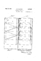
- the web13'comprises alternate 1 it has, for its object, to provide an'evaporatrittle plate sections 15, 16, 17 and plane'sec- 1 ing apparatus of marked efiiciency, capable tions 18, 19 and 20,"connected by the. vertical of use in many fields of industry, but,particuportions 21, 22, 23, 24 and 25.
- the weblA larly adapted and intended for use in di'scomprises the alternate riflie'plate sections posing of the saltwater that is broughtto 26, 27, and 28, and plane sections 29-, 30, conthe surface ofthe' ground, in the production nected by the vertlcal portions .31, 32 and of oil-and gas from wells. 33f53-.
- the webs and the wedge shaped 7 1o The problem of disposingof thissalt water partltions aresoarranged, with respect to becomes increasingly'great'ea'ch year. Every each other, as to form three separate paths,
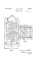
- Fig. l is a vertical sectional View of an thereinthrougha pipeA at the lower portion apparatus constructed'inaccordance with the ofthe waterjaicket. From'thewaterjacket 1 fthe water is delivered-through a; port 513, so Fig. 2 is a horizontal sectional view thereinto the uppermost wedge 'shaped chamber through, on;1ine'-2'2 of-Fig. 1,; f 8 (see Fig.4). It circulates through said, -Fig.
- FIG. 3 is an elevation with the outervja'cket chamber across the widthofftheapparatus
- Fig.4 is a view, like Fig. 3, but at right the inner casing and aroundthe corner of angles'thereto; said casing to the rear side of the wedge
- Like numerals designate correspondlng shaped chamber 9, entering saidchamber at in section and the inner jacket in elevation, andde'aves thef'chamber through-a pipe G, n
- The; evaporating apparatus ofthe'pre'sent. whichyextends obliquely across the; inner 9o '7 V invention comprises an outer wall 5, and an wall'6, and enters the wedge shaped cham- Y inner wall 6",the space between these two ber 10 atcF.
- the water leavesthe chamber walls constituting a liquid, jacket 7. Wedge 10 through a pipe whichextends obliquely shaped compartments 8, 9,10, 11 and 12,proacross the inner wall of, the water jacket ject fromt'he opposite side walls of the inner and enters the wedge shaped'chamber 11, walls'6, these compartmentsbeing-fluid tight at H.
- Ilwo webs 13-14 are tus and enters the wedgeshapedchamber disposed withinthespace bounded by the 12, at J; Thislmovement'of thefcrudesalt inner walls 6, these webs being of zig-z'ag water through the wedge shaped chambers is '10) successively, over rifile plates 15, 26, 16, 27;
- An evaporating apparatus of the character described comprising an inner chamber surrounded by a water jacket, a pair of zigzag webs, each comprising a plurality of riffle plates, saidwebs lying in internested but spacedrelation', and the spaces between said webs constituting acourse of water travel, means for conducting a liquid tovbe Vaporizedthrouigh the Waterj acket to preheat the same, means for delivering the liquid to be vaporizedto the uppermost of the riflle plates, and wedge shaped compartments pro ecting alternately fromthe opposite sides of the inner chamber, the upper and lowerfaces of whichiliein substantial:parallelism with the adjacent portions of the respective webs,.the interiors of said com Jartments constituting parts of the path 0 travel: of the liquid throu h the water'jacket. a j
- I g devicevof-the characterdescribed comprising. an inner compartment. surroundedby a water acket, a plurality otclosed wedge shaped compartments projecting; alternately in opposite directions fromtheoppositeinner side walls of thewater jacket and into said inner compartment, a. pair of zig-z'ag Webs, each shaped to form a plurality of rifiie plates and plane portions connected by ;ver
- a device of the character-described comprising an inner compartment surrounded by a water jacket, a pluralitybf closed wedge shaped chambers projecting alternately in opposite directions from the opposite inner side walls of the water jacket and into said inner compartment, a pair of zig-zag webs, each shaped to form a plurality of riflle plates and plane portions connected by vertical runs, said webs lying in internested but spaced relation with respect to each other, and with respect to the faces of said closed chambers,
Landscapes
- Chemical & Material Sciences (AREA)
- Chemical Kinetics & Catalysis (AREA)
- Heat-Exchange Devices With Radiators And Conduit Assemblies (AREA)
Description
EVAPORATING APPARATUS- Filed May 16, 1950 2 Shets-Sheet 1 INVENTOR.
i ,1, Ul a/1 0406 @(W A TTORNEY Filed May 16. 1930 2 Sheets-Sheet 1 INVENTOR.
am Aa A TTORNEY$ Patented May 10, 193?. l I n T UNrr-ED- STATES T T 04F I3 L; 1"
HAROLD H. ELLISTON, or INDEPENDENCE, KANSAS EVAPORATING APPARATUS i o l I Application filed May 1 1930. Serial No. 452546. 7
.This invention relates, to an 'evaporating formation and lying'in spacedfrelation to apparatus and method ofusing the same, and each other. The web13'comprises alternate 1 it has, for its object, to provide an'evaporatriiile plate sections 15, 16, 17 and plane'sec- 1 ing apparatus of marked efiiciency, capable tions 18, 19 and 20,"connected by the. vertical of use in many fields of industry, but, particuportions 21, 22, 23, 24 and 25. The weblA larly, adapted and intended for use in di'scomprises the alternate riflie'plate sections posing of the saltwater that is broughtto 26, 27, and 28, and plane sections 29-, 30, conthe surface ofthe' ground, in the production nected by the vertlcal portions .31, 32 and of oil-and gas from wells. 33f53-. The webs and the wedge shaped 7 1o The problem of disposingof thissalt water partltions aresoarranged, with respect to becomes increasingly'great'ea'ch year. Every each other, as to form three separate paths,
large oil company is continually confronted indicated by the arrows w -6 c. The ar- With' claims for salt waterdamage,because rows 05 andc indicateythepath'of travel of of the pollution of streams and wells, and heat from chambers 34: and 34*, which may 1'5 injury to the land'caused 'eitherby direct contaln gas burnersindicated'by pipes 85;, 55. passage of the salt waterover the surface of 35*, or may receive products of combustion the land or subterranean leakage'of ponds from externalsources, as, for 'eirampl'e',-from built'by the oil companies to retain the water; an internal combustion engine, or engines,
, Many States have enacted statutes prohibit through said pipes 35,- 35. The path bis-a 1 ing the permitting of salt water toflow over courseofliquid travel over theriflle plates, 1
the surface of the ground or into streams,'and as will be hereinafter described. I
it becomes increasingly important to provide When i salt water is produced from a a practicable and economical method of meetpumplng 011 well itissepar'ated; from the "oil a ing thissituation; 1n a'separ'a'tor which is located from 10'to An apparatus adapted to accomplish the 15 feet above; the surfacejlof thezground. 7 I
3 invention,
foregoing object is illustrated in the accom- The water; consequently, may be conducted panying drawings,-wherein by gravity to'the' evaporator and delivered Fig. l is a vertical sectional View of an thereinthrougha pipeA at the lower portion apparatus constructed'inaccordance with the ofthe waterjaicket. From'thewaterjacket 1 fthe water is delivered-through a; port 513, so Fig. 2 is a horizontal sectional view thereinto the uppermost wedge 'shaped chamber through, on;1ine'-2'2 of-Fig. 1,; f 8 (see Fig.4). It circulates through said, -Fig. 3 is an elevation with the outervja'cket chamber across the widthofftheapparatus Fig.4 is a view, like Fig. 3, but at right the inner casing and aroundthe corner of angles'thereto; said casing to the rear side of the wedge Like numerals designate correspondlng shaped chamber 9, entering saidchamber at in section and the inner jacket in elevation, andde'aves thef'chamber through-a pipe G, n
which extends'obliquely across one side of V parts in allofithe figures of the drawings. D, leaving-1 saidl'chamberthroughiipipe. E, i I
. p45 The; evaporating apparatus ofthe'pre'sent. whichyextends obliquely across the; inner 9o '7 V invention comprises an outer wall 5, and an wall'6, and enters the wedge shaped cham- Y inner wall 6",the space between these two ber 10 atcF. The water leavesthe chamber walls constituting a liquid, jacket 7. Wedge 10 through a pipe whichextends obliquely shaped compartments 8, 9,10, 11 and 12,proacross the inner wall of, the water jacket ject fromt'he opposite side walls of the inner and enters the wedge shaped'chamber 11, walls'6, these compartmentsbeing-fluid tight at H. It leaves chamber 11 througlif pipel, v except for the entrance and exit ports'or'pipes which extends obliquely across the app'ara hereinafter described. Ilwo webs 13-14 are tus and enters the wedgeshapedchamber disposed withinthespace bounded by the 12, at J; Thislmovement'of thefcrudesalt inner walls 6, these webs being of zig-z'ag water through the wedge shaped chambers is '10) successively, over rifile plates 15, 26, 16, 27;
17 and 28,. entering a compartment 37' through the channel 38, the lower end of which is disposed below the level ofan overfiow, pipe 39, Withtheresult that a liquid seal is maintained at the lower end of the channel 38. It will be observed-that both the upper and lower surfaces of the rifile -plates are disposed to receive heat from eitherthe channel aor 0,.the hot gases-passing froinftlie apparatus through the passages lO! andj tl, and the vapors passing a from, the apparatus, at 42.
, It: is to'be understood that the construction illustrated in the accompanying drawings ismerely exemplary, and that the numberof riflie plates and: the number of preheating compartments or chambers, 8,. 9, etc.,.may. be multiplied to'any desired eX-. tent. There is a considerable degree of waste heat,--.available'inthe modern well pumping plants, and-the number ofirifile plates may be increased to the point where. all of the heating capacityof the'plant may be utilized in the-evaporationlprocess.
.Since the water passage bis water sealed by terminating; beneath the liquid level in compartment: 37, it follows that the evapration-of the liquidmay be carried out under sub-normal pressures,- ,byvirtue of which-the efficiency of. the apparatus. is furtherincreasech It will be observed that the rifile plates constitute a series of stairs with risers atthelower sides thereof, so that the liquid is-forcedtorun in a Wide shallow sheet over the. entire surface of the riflle plate and make the entire surface available 'for 'direct heattransfer toithe liquid by the hot gases passing; directly under and over these riflle plates- .The number. ofr'iflieplates which will be installed in any one apparatus will usually: be governed by the temperature of the outgoing. gases or products of combustiona By virtue of the apparatus herein Shownand described, the volumeof salt waten-whichinust. be disposed of maybe reducedto atrelatively small" quantity. of concentrated liquid which leaves the compartment 37 through the overflow pipe 39, and this-is insuch volume that it maybe readily disposed of without contamination of adja centilands, streams, or the like.
"It is to be understood that the invention is not limited to the particular arrangement shownjand' described, but that it includes within its purview whatever changes fairly comewithin'either the terms or. the spirit of th'eappended claims.
Having described my invention, what I claim is: I
1. An evaporating apparatus of the character described, comprising an inner chamber surrounded by a water jacket, a pair of zigzag webs, each comprising a plurality of riffle plates, saidwebs lying in internested but spacedrelation', and the spaces between said webs constituting acourse of water travel, means for conducting a liquid tovbe Vaporizedthrouigh the Waterj acket to preheat the same, means for delivering the liquid to be vaporizedto the uppermost of the riflle plates, and wedge shaped compartments pro ecting alternately fromthe opposite sides of the inner chamber, the upper and lowerfaces of whichiliein substantial:parallelism with the adjacent portions of the respective webs,.the interiors of said com Jartments constituting parts of the path 0 travel: of the liquid throu h the water'jacket. a j
2; I g devicevof-the characterdescribed,comprising. an inner compartment. surroundedby a water acket, a plurality otclosed wedge shaped compartments projecting; alternately in opposite directions fromtheoppositeinner side walls of thewater jacket and into said inner compartment, a. pair of zig-z'ag Webs, each shaped to form a plurality of rifiie plates and plane portions connected by ;ver
ticalruns, saidw'ebs lying in-internested but spaced relationwith respect to'each other; and with respect to the faces of saidclosedchamhere, the space between the confrontin'gfaees of the. webs constituting. a course of water trayel, andthe spaces between the respective webs and their associated closed chambers constituting;coursesotheattravel; and means for conducting a liquid to be vaporized to the water jacket, and means for conducting the said; liquid from the. saidwater jacket suc cessively through the several closedchambers,
andmeans for conducting said. liquid from the last ofsaidclosed chambers to the uppermost of the rifile plates. 3, A-device of. the character described, comprising an inner. compartmentsurroundediby a water jacket, aplurality, of closed, wedge shaped compartments pro ectingalternately in opposite directions from the opposite=in nerside walls of thewater jacket-and intosa id inner compartment, a pair otzig-zgg webs,
each shaped to forma pluralityofri and plane. portions connected :by'vertical runs, sai'di webs lying. internested but spacedvre lation with respect toeach other, and with respect to the faces of said closedchambers,
e plates the spacebetweeni the confronting faces of the webs constituting a course ofw-ater travel, and the spaces between the respectivewebs" and'theirassociated closed chambers constituting courses otheat travel,-means for fconducting a liquid to be vaporizedrtothewatei'. jacket, means for conducting the said-liquid from. the said. Water jacket successively through the several closed chambers, means for conducting said liquid from the last of said closed chambers to the uppermostof the riflie plates, and a liquid compartment at the lower portion of the apparatus into which the liquid is finally discharged and in which the said water channel is water sealed.
4. A device of the character-described, comprising an inner compartment surrounded by a water jacket, a pluralitybf closed wedge shaped chambers projecting alternately in opposite directions from the opposite inner side walls of the water jacket and into said inner compartment, a pair of zig-zag webs, each shaped to form a plurality of riflle plates and plane portions connected by vertical runs, said webs lying in internested but spaced relation with respect to each other, and with respect to the faces of said closed chambers,
the space between the confronting faces of the webs constituting a course of water travel, and the spaces between the respective webs and their associated closed chambers constituting courses of heat travel, means for conducting a liquid to be vaporized to the water jacket, means for conducting said liquid from the said water jacket successively through the several. closed chambers, means for conducting said liquid from the last of said closed chambers to the uppermost of the rifiie plates, a liquid compartment at the lower portion of the apparatus-into which the liquid is finally discharged and in which the said water channel is water sealed, and a concentrated liquid outlet from the last named compartment.
In testimony whereof I affix my signature.
HAROLD H. ELLISTON'.
Priority Applications (1)
| Application Number | Priority Date | Filing Date | Title |
|---|---|---|---|
| US452946A US1857535A (en) | 1930-05-16 | 1930-05-16 | Evaporating apparatus |
Applications Claiming Priority (1)
| Application Number | Priority Date | Filing Date | Title |
|---|---|---|---|
| US452946A US1857535A (en) | 1930-05-16 | 1930-05-16 | Evaporating apparatus |
Publications (1)
| Publication Number | Publication Date |
|---|---|
| US1857535A true US1857535A (en) | 1932-05-10 |
Family
ID=23798610
Family Applications (1)
| Application Number | Title | Priority Date | Filing Date |
|---|---|---|---|
| US452946A Expired - Lifetime US1857535A (en) | 1930-05-16 | 1930-05-16 | Evaporating apparatus |
Country Status (1)
| Country | Link |
|---|---|
| US (1) | US1857535A (en) |
Cited By (5)
| Publication number | Priority date | Publication date | Assignee | Title |
|---|---|---|---|---|
| US3305454A (en) * | 1965-02-19 | 1967-02-21 | Desal Ltd | Series evaporator-tray compressor type vacuum still |
| US3444049A (en) * | 1962-08-23 | 1969-05-13 | Weir Westgarth Ltd | Vertical multistage distillation apparatus |
| US3536591A (en) * | 1962-07-02 | 1970-10-27 | Gen Electric | Multiple effect distillation apparatus |
| US4657638A (en) * | 1985-07-29 | 1987-04-14 | University Of Florida | Distillation column |
| US4744868A (en) * | 1985-07-29 | 1988-05-17 | University Of Florida | Distillation column and method |
-
1930
- 1930-05-16 US US452946A patent/US1857535A/en not_active Expired - Lifetime
Cited By (5)
| Publication number | Priority date | Publication date | Assignee | Title |
|---|---|---|---|---|
| US3536591A (en) * | 1962-07-02 | 1970-10-27 | Gen Electric | Multiple effect distillation apparatus |
| US3444049A (en) * | 1962-08-23 | 1969-05-13 | Weir Westgarth Ltd | Vertical multistage distillation apparatus |
| US3305454A (en) * | 1965-02-19 | 1967-02-21 | Desal Ltd | Series evaporator-tray compressor type vacuum still |
| US4657638A (en) * | 1985-07-29 | 1987-04-14 | University Of Florida | Distillation column |
| US4744868A (en) * | 1985-07-29 | 1988-05-17 | University Of Florida | Distillation column and method |
Similar Documents
| Publication | Publication Date | Title |
|---|---|---|
| US1432351A (en) | Filter | |
| US2009510A (en) | Oil clarifier | |
| US1857535A (en) | Evaporating apparatus | |
| US349990A (en) | Paul henbi auguste gaillet and louis henbi simon hubeet huet | |
| US1966133A (en) | Heating device | |
| US1658063A (en) | Plural-stage heater | |
| US1690537A (en) | Separation of liquids | |
| US1692446A (en) | Heatable sludge-digestion chamber for sewage treatment | |
| US549435A (en) | cabell | |
| US415646A (en) | Vassily kusnezov | |
| US699572A (en) | Apparatus for refining oil. | |
| US1608691A (en) | House electric | |
| US1456312A (en) | Combined sludge separating and drying basin | |
| US1351433A (en) | Steam-separator | |
| US1289439A (en) | Smoke washer or purifier. | |
| US462275A (en) | mcgaiian | |
| US1754789A (en) | Oil separator | |
| US735693A (en) | Feed-water heater and purifier. | |
| US1621782A (en) | hopkins | |
| US604370A (en) | collier | |
| US147624A (en) | Improvement in feed-water heaters for steam-boilers | |
| US649116A (en) | Feed-water purifier for boilers. | |
| US1770217A (en) | Hot-water boiler | |
| US182844A (en) | Improvement in feed-water heaters | |
| SU548295A1 (en) | The device for the purification of oily water |