US1857529A - Conveyer chain - Google Patents
Conveyer chain Download PDFInfo
- Publication number
- US1857529A US1857529A US524699A US52469931A US1857529A US 1857529 A US1857529 A US 1857529A US 524699 A US524699 A US 524699A US 52469931 A US52469931 A US 52469931A US 1857529 A US1857529 A US 1857529A
- Authority
- US
- United States
- Prior art keywords
- links
- chain
- conveyer
- link
- walls
- Prior art date
- Legal status (The legal status is an assumption and is not a legal conclusion. Google has not performed a legal analysis and makes no representation as to the accuracy of the status listed.)
- Expired - Lifetime
Links
Images

Classifications
-
- F—MECHANICAL ENGINEERING; LIGHTING; HEATING; WEAPONS; BLASTING
- F16—ENGINEERING ELEMENTS AND UNITS; GENERAL MEASURES FOR PRODUCING AND MAINTAINING EFFECTIVE FUNCTIONING OF MACHINES OR INSTALLATIONS; THERMAL INSULATION IN GENERAL
- F16G—BELTS, CABLES, OR ROPES, PREDOMINANTLY USED FOR DRIVING PURPOSES; CHAINS; FITTINGS PREDOMINANTLY USED THEREFOR
- F16G13/00—Chains
- F16G13/02—Driving-chains
- F16G13/10—Driving-chains with universal joints
-
- B—PERFORMING OPERATIONS; TRANSPORTING
- B65—CONVEYING; PACKING; STORING; HANDLING THIN OR FILAMENTARY MATERIAL
- B65G—TRANSPORT OR STORAGE DEVICES, e.g. CONVEYORS FOR LOADING OR TIPPING, SHOP CONVEYOR SYSTEMS OR PNEUMATIC TUBE CONVEYORS
- B65G17/00—Conveyors having an endless traction element, e.g. a chain, transmitting movement to a continuous or substantially-continuous load-carrying surface or to a series of individual load-carriers; Endless-chain conveyors in which the chains form the load-carrying surface
- B65G17/06—Conveyors having an endless traction element, e.g. a chain, transmitting movement to a continuous or substantially-continuous load-carrying surface or to a series of individual load-carriers; Endless-chain conveyors in which the chains form the load-carrying surface having a load-carrying surface formed by a series of interconnected, e.g. longitudinal, links, plates, or platforms
- B65G17/08—Conveyors having an endless traction element, e.g. a chain, transmitting movement to a continuous or substantially-continuous load-carrying surface or to a series of individual load-carriers; Endless-chain conveyors in which the chains form the load-carrying surface having a load-carrying surface formed by a series of interconnected, e.g. longitudinal, links, plates, or platforms the surface being formed by the traction element
- B65G17/086—Conveyors having an endless traction element, e.g. a chain, transmitting movement to a continuous or substantially-continuous load-carrying surface or to a series of individual load-carriers; Endless-chain conveyors in which the chains form the load-carrying surface having a load-carrying surface formed by a series of interconnected, e.g. longitudinal, links, plates, or platforms the surface being formed by the traction element specially adapted to follow a curved path
-
- B—PERFORMING OPERATIONS; TRANSPORTING
- B65—CONVEYING; PACKING; STORING; HANDLING THIN OR FILAMENTARY MATERIAL
- B65G—TRANSPORT OR STORAGE DEVICES, e.g. CONVEYORS FOR LOADING OR TIPPING, SHOP CONVEYOR SYSTEMS OR PNEUMATIC TUBE CONVEYORS
- B65G2201/00—Indexing codes relating to handling devices, e.g. conveyors, characterised by the type of product or load being conveyed or handled
- B65G2201/02—Articles
Definitions
- This invention relates to improvements in conveyer chains.
- the primary object of the invention is to provide a conveyer chain having readily detachable and interchangeable links, alternate ones of which have substantially plane surfaces, so that a box or the like supported thereby may be carried to a certain station, and then be halted by some obstructing means, without interfering with the continuous especially advantageous in the handling of boxes of milk bottles within a dairy, for a box placed on the conveyer will be carried automatically to a desired station, and may then remain on the belt in an immovable position While the belt continues to travel beneath the box.
- Another object is to furnish a conveyer of this character having links connected by universal joints to allow the chain to travel in various paths without interference by kinking of portions of the chain. T he universal joints are of such construction however, that the links cannot revolve lengthwise of the chain.
- FIG. 1 is a top plan view of a portion of a conveyer in which the invention is incorporated.
- Fig. 2 is a front elevation of the sax rm.
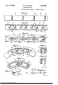
- Fig.3 is an enlarged side elevation of a portion of one of the conveyer chains.
- Fig. 4 is a longitudinal vertical sectional view of the same.
- Fig. 5 is a bottom plan view of the same, partly in horizontal section.
- Fig. 6 is a side elevation partly in longi-. tudinal vertical section, of a portion-of the chain, and illustrating the manner in which the links may pass around a sprocket wheel.
- Fig. 7 is a vertical sectional view of one of the links on the line 7-7 of Fig. 6'.
- Fig. 8 is a horizontal sectional view of some travel of the chain. Such a construction is mouth 20 at that end of the link A. Now, a
- Fig. 9 is a form of link.
- 11 designates a conveyer frame having tracks 12 which guide conveyer chains 13.
- the tracks 12 may extend uphill or down, and may turn corners, as indicated in Fig. 1,
- the chains engage sprocket wheels 14 mounted on shafts 15.
- sprocket wheels 14 mounted on shafts 15.
- "Only one perspective view of a modified of these shafts and its sprocket 'wheels is illustrated, and it will be noted that either one of the shafts may be driven by any suitable prime mover for causing the travel of the chains.
- lower tracks 16 are positioned iIIl-' mediately below the tracks 12 for the purpose of guiding the lower runs of the chains.
- each chain is made up of two types of links A and B, and each link A is ofsubstantially channel shapelengthwise thereof, the bottom of the channel forming a plane surface 17
- the walls 18 of the channel are spaced apart a greater distance at their medial portions, as indicated at 19, than at their end portions, as indicated at20,"an'd the extremities of the Walls are spaced apart by flared mouths 21.
- each channel form pockets 21 at the ends of the link, and these pockets form sockets to receive balls 22 forming theends of the links B.
- a relatively narrow web 23 connects the balls of each of the links B, and extends through the flared mouths 20, and this provides universal joints so that the chain made up of such links may flex in various planes as indicated in Figs. 6 and 8.
- the notches 19 not only provide a gateway for the entrance of the ball 22, but the end walls 24 of such notches form abutments for the engagement of the teeth of the sprocket wheel 14, and if desired, one wall of each channel may be notched as indicated at 25 in Figs. 9 and 10, for the reception of a tooth of the sprocket wheel.
- the links may be made of any suitable material, but I prefer to make them of metal.
- each web 23 is flat and of substantially the same height as each of the links A, and the mouths 2O are so shaped as to co-operate with the webs 23 to prevent rotation of the links lengthwise of the chain.
- a conveyer chain comprising first and second links, each of the first links being of channel shape lengthwise and having side walls, said walls forming pockets in the end portions of each link, each of the second links including balls engaging a pair of pockets of adjacent first links, and a web joining the balls, the ends of the walls of each of the first links forming flaring mouths through which the webs extend, each of said webs and each mouth being shaped to prevent rotation of the links relatively to one another lengthwise of the chain.
- a conveyer chain comprising first and second links, each of the first links being of 7 channel shape lengthwise and having side walls, said walls forming pockets in the end portions of each link, each of the second links including balls engaging a pair of pockets of adjacent first links, and a Web joining the balls, one of the side walls of each of the first links having a notch extending toward the bottom of the channel to provide a sprocket wheel tooth abutment.
- a conveyer chain comprising first and second link, each of the first links being of channel shape lengthwise and having a flat web and opposite side walls, said walls forming curved pockets in the end portions of each link, the edges of the ends of: the side walls forming flaring mouths, each of the second links including balls engaging a pair of pockets of adjacent first links, and aweb joining the balls and extending through the flaring mouths of the last mentioned links, the last mentioned web being of materially less width than any of said mouths to permit relative turning movement of the links laterally, each of said last mentioned webs being of substantially the same height as each of the first links to prevent rotation of the links rlelatively to one another lengthwise of the c mm.
Landscapes
- Engineering & Computer Science (AREA)
- General Engineering & Computer Science (AREA)
- Mechanical Engineering (AREA)
- Chain Conveyers (AREA)
Description
May 10, 1932.
W. R. COPPAGE CONVEYER CHAIN Filed March 23, 1951 2 Sheets-Sheet 1 May 10, 1932. w, COPPAGE 1,857,529
CONVEYER CHAIN Filed March 23, 1931 2 Sheets-Sheet 2 Patented May 10, 1932 [UNITED STATES WILLIAM B. GOPIAGE, F CHERRYDALE, VIRGINIA GONVEYER CHAIN Application filed March 23, 1931. Serial No. 524,699.
This invention relates to improvements in conveyer chains.
The primary object of the invention is to provide a conveyer chain having readily detachable and interchangeable links, alternate ones of which have substantially plane surfaces, so that a box or the like supported thereby may be carried to a certain station, and then be halted by some obstructing means, without interfering with the continuous especially advantageous in the handling of boxes of milk bottles within a dairy, for a box placed on the conveyer will be carried automatically to a desired station, and may then remain on the belt in an immovable position While the belt continues to travel beneath the box.
Another object is to furnish a conveyer of this character having links connected by universal joints to allow the chain to travel in various paths without interference by kinking of portions of the chain. T he universal joints are of such construction however, that the links cannot revolve lengthwise of the chain. With the foregoing objects outlined and with other objects in view which will appear as the description proceeds, the invention consists in the novel features hereinafter described in detail, illustrated in the accompanying drawings, and more particularly pointed out in the appended claims.
In the drawings, 1 V Fig. 1 is a top plan view of a portion of a conveyer in which the invention is incorporated.
Fig. 2 is a front elevation of the sax rm.
Fig.3 is an enlarged side elevation of a portion of one of the conveyer chains.
Fig. 4 is a longitudinal vertical sectional view of the same.
Fig. 5 is a bottom plan view of the same, partly in horizontal section.
Fig. 6 is a side elevation partly in longi-. tudinal vertical section, of a portion-of the chain, and illustrating the manner in which the links may pass around a sprocket wheel.
Fig. 7 is a vertical sectional view of one of the links on the line 7-7 of Fig. 6'.
Fig. 8 is a horizontal sectional view of some travel of the chain. Such a construction is mouth 20 at that end of the link A. Now, a
of the links, and illustrating the manner in which the chain may pass around a corner or the like.
Fig. 9 is a form of link. v Fig. 10 1s a sectional view of the same on the line 10 10 of Fig. 9.
Referring to the drawings, 11 designates a conveyer frame having tracks 12 which guide conveyer chains 13. Owing to the spe- 80 cial construction of my chain, the tracks 12 may extend uphill or down, and may turn corners, as indicated in Fig. 1, At the ends of the track, the chains engage sprocket wheels 14 mounted on shafts 15. "Only one perspective view of a modified of these shafts and its sprocket 'wheels is illustrated, and it will be noted that either one of the shafts may be driven by any suitable prime mover for causing the travel of the chains. To prevent undue slack in the 7 chains, lower tracks 16 are positioned iIIl-' mediately below the tracks 12 for the purpose of guiding the lower runs of the chains.
In accordance with my invention, each chain is made up of two types of links A and B, and each link A is ofsubstantially channel shapelengthwise thereof, the bottom of the channel forming a plane surface 17 The walls 18 of the channel are spaced apart a greater distance at their medial portions, as indicated at 19, than at their end portions, as indicated at20,"an'd the extremities of the Walls are spaced apart by flared mouths 21.
The opposite walls of each channel form pockets 21 at the ends of the link, and these pockets form sockets to receive balls 22 forming theends of the links B. A relatively narrow web 23 connects the balls of each of the links B, and extends through the flared mouths 20, and this provides universal joints so that the chain made up of such links may flex in various planes as indicated in Figs. 6 and 8.
In connecting alink B to a link A, the ball 22 is introduced into the channel of the link A between. the medial portions 19 of the walls, and-is brou ht into contact with the" surface of the poo et 21, and at such time, the web 23 will project through the flared second link A may be connected to the other .ball of the link B and so on, until an endless chain of the desired length is made. Obviously, this construction allows quick replacement of any one of the links.
The notches 19 not only provide a gateway for the entrance of the ball 22, but the end walls 24 of such notches form abutments for the engagement of the teeth of the sprocket wheel 14, and if desired, one wall of each channel may be notched as indicated at 25 in Figs. 9 and 10, for the reception of a tooth of the sprocket wheel.
l/Vhen links of this character are used in the chains 13, it will be understood that their flat surfaces 17 come in engagement with the box that is to be conveyed, and after the box has travelled to a desired station, if an immovable obstruction is placed across the tracks 12, the box will halt without attention by an attendant, but the chains can continue to travel for the smooth surfaces 17 will simply slide underneath the box.
The links may be made of any suitable material, but I prefer to make them of metal.
It will be noted that each web 23 is flat and of substantially the same height as each of the links A, and the mouths 2O are so shaped as to co-operate with the webs 23 to prevent rotation of the links lengthwise of the chain.
While I have disclosed what I now consider to be a preferred embodiment of the invention in such manner that the same may be readily understood by those skilled in the art, I am aware that changes may be made in the detailsdisclosed, without departing from the spirit of the invention, as expressed in the claims.
What I claim and desire to secure by Letters Patent is: 1. A conveyer chain comprising first and second links, each of the first links being of channel shape lengthwise and having side walls, said walls forming pockets in the end portions of each link, each of the second links including balls engaging a pair of pockets of adjacent first links, and a web joining the balls, the ends of the walls of each of the first links forming flaring mouths through which the webs extend, each of said webs and each mouth being shaped to prevent rotation of the links relatively to one another lengthwise of the chain.
2. A conveyer chain comprising first and second links, each of the first links being of 7 channel shape lengthwise and having side walls, said walls forming pockets in the end portions of each link, each of the second links including balls engaging a pair of pockets of adjacent first links, and a Web joining the balls, one of the side walls of each of the first links having a notch extending toward the bottom of the channel to provide a sprocket wheel tooth abutment.
3. A conveyer chain comprising first and second link, each of the first links being of channel shape lengthwise and having a flat web and opposite side walls, said walls forming curved pockets in the end portions of each link, the edges of the ends of: the side walls forming flaring mouths, each of the second links including balls engaging a pair of pockets of adjacent first links, and aweb joining the balls and extending through the flaring mouths of the last mentioned links, the last mentioned web being of materially less width than any of said mouths to permit relative turning movement of the links laterally, each of said last mentioned webs being of substantially the same height as each of the first links to prevent rotation of the links rlelatively to one another lengthwise of the c mm.
In testimony whereof I have signed this specification.
WILLIAM R. COPPAGE.
Priority Applications (1)
| Application Number | Priority Date | Filing Date | Title |
|---|---|---|---|
| US524699A US1857529A (en) | 1931-03-23 | 1931-03-23 | Conveyer chain |
Applications Claiming Priority (1)
| Application Number | Priority Date | Filing Date | Title |
|---|---|---|---|
| US524699A US1857529A (en) | 1931-03-23 | 1931-03-23 | Conveyer chain |
Publications (1)
| Publication Number | Publication Date |
|---|---|
| US1857529A true US1857529A (en) | 1932-05-10 |
Family
ID=24090307
Family Applications (1)
| Application Number | Title | Priority Date | Filing Date |
|---|---|---|---|
| US524699A Expired - Lifetime US1857529A (en) | 1931-03-23 | 1931-03-23 | Conveyer chain |
Country Status (1)
| Country | Link |
|---|---|
| US (1) | US1857529A (en) |
Cited By (2)
| Publication number | Priority date | Publication date | Assignee | Title |
|---|---|---|---|---|
| US2775338A (en) * | 1955-05-16 | 1956-12-25 | Harry L Schmalzried | Channel bars connecting link |
| US3116824A (en) * | 1961-05-24 | 1964-01-07 | Baker Perkins Inc | Conveyor trough structure |
-
1931
- 1931-03-23 US US524699A patent/US1857529A/en not_active Expired - Lifetime
Cited By (2)
| Publication number | Priority date | Publication date | Assignee | Title |
|---|---|---|---|---|
| US2775338A (en) * | 1955-05-16 | 1956-12-25 | Harry L Schmalzried | Channel bars connecting link |
| US3116824A (en) * | 1961-05-24 | 1964-01-07 | Baker Perkins Inc | Conveyor trough structure |
Similar Documents
| Publication | Publication Date | Title |
|---|---|---|
| US3262550A (en) | Conveyor chain | |
| US1768534A (en) | Conveyer | |
| US1000107A (en) | Conveyer. | |
| US1857529A (en) | Conveyer chain | |
| US3497056A (en) | Magnetic conveyor drive unit | |
| US2141876A (en) | Conveyer | |
| US3389662A (en) | Low profile conveyor | |
| US2884118A (en) | Articular conveyor chain | |
| US1854334A (en) | Conveyer | |
| US1692832A (en) | Conveyer-belt guide | |
| US2953240A (en) | Package conveyor | |
| US1869050A (en) | Conveyer chain | |
| US2955699A (en) | Conveying apparatus | |
| GB288954A (en) | Improvements in or relating to conveying apparatus | |
| GB316233A (en) | Improvements in or relating to links and chains for conveyors for goods adapted to be poured or shot and links or chains therefor | |
| US1446270A (en) | Troughing idler for conveyer belts | |
| US2290981A (en) | Conveyer | |
| US1833874A (en) | Clearing out strap for belt conveyers | |
| US1453702A (en) | Universal conveyer chain | |
| US1755450A (en) | Conveyer and driving-motor construction | |
| US1786343A (en) | Universal drag conveyer | |
| US1714721A (en) | Conveyer | |
| GB984757A (en) | Endless chain conveyors | |
| US2201665A (en) | Conveyer belt | |
| GB243082A (en) | Improvements in or relating to chain elevators, conveyers or the like for storing ordisplaying goods |