US1857525A - Gas burning apparatus - Google Patents
Gas burning apparatus Download PDFInfo
- Publication number
- US1857525A US1857525A US438379A US43837930A US1857525A US 1857525 A US1857525 A US 1857525A US 438379 A US438379 A US 438379A US 43837930 A US43837930 A US 43837930A US 1857525 A US1857525 A US 1857525A
- Authority
- US
- United States
- Prior art keywords
- mixing chamber
- manifold
- fuel
- furnace
- combustion
- Prior art date
- Legal status (The legal status is an assumption and is not a legal conclusion. Google has not performed a legal analysis and makes no representation as to the accuracy of the status listed.)
- Expired - Lifetime
Links
- 239000000446 fuel Substances 0.000 description 31
- 238000002485 combustion reaction Methods 0.000 description 20
- 239000000203 mixture Substances 0.000 description 11
- 208000028659 discharge Diseases 0.000 description 9
- XLYOFNOQVPJJNP-UHFFFAOYSA-N water Substances O XLYOFNOQVPJJNP-UHFFFAOYSA-N 0.000 description 9
- 238000010438 heat treatment Methods 0.000 description 7
- 230000000295 complement effect Effects 0.000 description 3
- 238000010276 construction Methods 0.000 description 3
- 238000005266 casting Methods 0.000 description 2
- 239000003245 coal Substances 0.000 description 2
- 210000005069 ears Anatomy 0.000 description 2
- 241001123248 Arma Species 0.000 description 1
- 206010026749 Mania Diseases 0.000 description 1
- 230000006978 adaptation Effects 0.000 description 1
- 239000010425 asbestos Substances 0.000 description 1
- 238000004140 cleaning Methods 0.000 description 1
- 229920000136 polysorbate Polymers 0.000 description 1
- 229910052895 riebeckite Inorganic materials 0.000 description 1
- 125000006850 spacer group Chemical group 0.000 description 1
- 238000006467 substitution reaction Methods 0.000 description 1
Images


Classifications
-
- F—MECHANICAL ENGINEERING; LIGHTING; HEATING; WEAPONS; BLASTING
- F24—HEATING; RANGES; VENTILATING
- F24H—FLUID HEATERS, e.g. WATER OR AIR HEATERS, HAVING HEAT-GENERATING MEANS, e.g. HEAT PUMPS, IN GENERAL
- F24H9/00—Details
- F24H9/18—Arrangement or mounting of grates or heating means
- F24H9/1809—Arrangement or mounting of grates or heating means for water heaters
- F24H9/1832—Arrangement or mounting of combustion heating means, e.g. grates or burners
- F24H9/1836—Arrangement or mounting of combustion heating means, e.g. grates or burners using fluid fuel
Definitions
- ATTORNEYS bined gas burner and water heater design, lnexpensive construction, and hi h efficiency which is so put together as to be Patented May 1c, 1932 it warren era 7 Gas unnrne, Arma WILLIAM ausrm nnoxnrrir, OEKINGSVILLE'ONTABIG, Carmina H Application'filed March a4, 1930; 'Seria1 No.438*, 3 79i
- My invention relates to improvements in gas burnersadapted to employ-either natural or manufactured gas andarranged and con structed to accomplish substantially complete 5 combustion of the gas with the maximum efficiency upon the minimum use of fuel.
- One particular and important embodiment relates to a combined gas burner. andawater heater.
- Another particular and'important 19 embodiment relates to the combination of my improved gas burner with the conventional furnace normally adapted for
- An object of my invention is the provision of a gas burner which achieves a high degree, I of efficiency and produces substantially complete combustion free from the collection of a deposit, in combination with heatingme'ch anism suchas a water heater or the fire pot of a furnace.
- the heater and I combustlon chamber are so relatively arranged that the heat is most effectively used and developed to be applied to the heater.
- Another object is the provision of'a comofsimplereadily disassembled for cleaningpurposes or substitution of various heating elements
- Another object is the provision in a fur-- nace of conventional design of an adaptation of my improved burner, which effectively heats the furnace wall as desired, and wherein a plurality of gas burners may be supplied Y in individually controlled units.
- a meritorious characteristic of my improved gas burner is thatI provide a manie fold which'receives gas fuel through asuitably controlled intake and discharges the same through a pluralityof minute nozzles,
- a mixing chamber which receives the fuel mixture throughfa series of Venturi intake tubes corresponding in number to the discharge nozzles in the manifold and arranged directly 'thereover but spaced therefrom to admit air into the fuelstream to enter the mixing chamber, and wherein the mixing chamber is suitably provided with outlet orifices for the fuel mixture which lead into a combustion chamber.
- heater the intake team fold has two spaced apart rows of discharge outlets and the mixing chamber is divided onerow of outlets and theother section positioned above the other row of'outlets.
- Each section is spaced above the'manifold and is provided with a series of tubular intake elements corresponding in number to the discharge outlets of the manifold and arranged intotwo sections, one'section positioned above directly thereover. but spaced" therefromto receivethe fuel therefrom and to establish a suction to intake air swith the'fuel.
- V The C0mbl1St101'L Ql'la1Ilb81 or space 1s arrangedbetween the two sectlons of the mixing chamber and each section has fuel mixture discharge outlets leading into the combustion chamber space andiopening toward the other section. and the burning, L
- the heating ieljets resulting j therefromfserve to heat the opposite section.
- a pluralityof" individually controlled segmental gas burners are arranged in spaced/apartrelationship ⁇ circumferentially around the circular wall of the fire pot in the conventional furnace,
- the products/of combustion are projected against the wallof the firepot.
- the mixing chamber of each burner becomesvery hot due to its proximity tothe combustion zone.
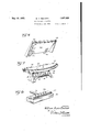
- Fig. 2 illustrates a view taken at right angles to the view of Fig.1 and showing a section through the structure shown in section in Fig. 1,
- FIG. 3 illustrates a fragmentary. sectional view through a furnace fire pot with one of my improved. burners adapted for furnace use installed therein
- I I H r Fig. 4 is a horizontal cross section taken on the line 44 of Fig. 3,
- Fig. 5 is a horizontal sectional view through a furnace fire pot showing a plurality of my individually controlled burner units arranged circumferentially therein, and
- Figs. 6, 7, and 8 are perspectives of the baffle plate, mixing chamber and manifold
- a tubular intake-element 18 is provided foreach discharge nozzle 15 and the mixing chamber sections are supported so that the tubular intakes are positioned above the discharge nozzles and in Figs. 1 and 2 the mixing chamber sections and the manifold are shown as pr0- vided with flanges 20 between which are positioned spacer elements 22 and the assembly is held together by bolts 24:.
- combustion chamber space or zone is between the two sections-16 of the mixing chamber and the fuel mixture enters this space through discharge orifices 26, a plurality of which are providedin the opposite faces of these mixing chamber sections.
- Auxiliary air is permitted'to enter the combustion chamber spacein any amount desired through the use of the perforated slide valve plate 28 which has apertures '30 arranged therealong.
- This slide valve is disposed to I travel over flanges 32 formed on. the opposite faces of the mixing chamber sections 16.
- the mixing chamber sections are provided at the ends with ears or flanges 34 which extend partially across the combustion chamber space as indicated in Fig. 2 and end plates 36 are secured theretoby bolts 38 and extend upwardly therefrom to support a top plate 40 which has an outlet42 for the products of combustion and forms withthe side plates 44 an enclosure about one or more heating ele-, .ments.
- the two side plates are removable and are merely inserted at the top underneath the side flanges formed on the top plate 40 and on the bottom inside of ears as formed on the 5 on the outside and an asbestos sheet 52 posi tioned between'the finish plate and the body portion of the plate 44.
- the heating element is here indicated as comprising upper and lower header elements 54 communicating with each other through 0 vertical water tubes 56.
- the side plates are shown as provided with ,baflie elements 58 which partially embrace the water tubes and with heat retaining vertical fins 60 extending between the water tubes.
- the gas fuel is discharged through the nozzles 15 from the manifold and passes upwardly through the intake tubes 18 into the two sections of the mixing chamber and is there mixed with air which is taken in through the tubes 18 and this fuel mixture discharges into the combustion chamber space between the two sections of the mixing chamberand additional air is admitted into such space through inanipulation of the slide valve 28 and the productsof combustion pass upwardly into the enclosure 7 formed by the end and side walls heretofore described to be suitably exhausted.
- the mixing chamber sections become substantially red hot during combustion and the fins 60 likewise become very hot and the combustion operation is thorough and complete and a high degree of efliciency is attained; It will be apparent that though a.
- Each gas burner unit comprises an intake manifold 82 having an upwardly extending ridge portion 84 which is provided with a plurality of minute fuel discharge nozzles 86.
- the mixing chamber comprises a mixing chamber portion proper indicated as 88 and which communicates with the manifold to receive fuel therefrom through a portion. formed by two complementary castings 90 held together by b'olts92 and adapted, as
- the mixing chamber supports a bafiie plate 99 which is provided with two prongs, or lugs, 100 that extend through apertures provided in thetop wall of the mixing chamber to sup port the baffle plate and is provided with wings 102 at the ends and with lugs, or projections, 104 one at each end extending toward the wall of the furnace to support the baffle plate thereagainst.
- the baffle plate has an upper marginwhich is curved as shown in Fig. 5 of the drawings but is spaced from the furnace wall. supported as described upon the mixing chamber so that it may be taken off to facilitate cleaningof the discharge nozzles of the mixing chamber.
- the mixing chamber has a curved face arranged opposite the wall of the furnace and a series of discharge nozzles 106 through which the fuel mixture is discharged toward the Wall of the furnace and into the space be tween the baflie plate and the furnace wall.
- each burner may be operated individually and apart from every other burner so that only that amount of fuel need be used depending upon the amount of heat desired to be produced and that that portion of the furnace wall which is heated will be highly heated and the combustion will be substantially complete.
- the fuel is drawn into the mixing chamber ventional furnace provided, with grate .bars, a plurality of individual gasxburner: units having individual fuel inlets individually 1 through the tubular intakes andmixed with air entering through the inlet 98 which is also drawn upwardly into the mixing cham ber and the highly heated condition ofthe This bafile plate'is movably.
- the mixing chamber is removably mounted upon .the'manifold andthe lower forked portion straddles the ridge on the upper face of the manifold to position itself thereon.
- the baffle plate has lugs Whichare received in recesses formed adjacent to the rear edge of the mixing chamber in its upper face and is therefore removably supported upon the mixing chamber. This type of 'con-' struction facilitates'the assembling and disassembling of the unit which makes the cleaning of the same more easy.
- WhatIclair'nz' i i 1. In combination with a fire potof a conventional furnace provided with grate "bars, a plurality ofindividualgas burner units.
- each unit having an intake manifold provided with a" gas fuel inlet and with a plurality of.
- a mixingchamber positioned spaced above said manifold and having a plurality of tubular intakes, one intake for each nozzle of-the manifold positioned spaced above said nozzle to admit air into the fuel' stream, a bafiie plate extending upwardly V vided with fuel mixture discharge nozzles from the mixing'chamberprojectingtow'ard the furnace wall, said mixing chamber pro- I r adapted to direct the fuel mixture toward the furnace wall into the space between the furnace wall and the baflle plate.
- each burner unit having a manifold provided with an indimanifold provided with an upwardly extending-ridge having a plurality of minute dis charge nozzles, a'mixing chamber having a part adapted toremovably straddle the ridge of the manifold to support the mixing chamber thereupon and havinga plurality of tubular intakes,.one for each discharged nozzle ofthe manifold arranged spaced thereabout and extending upwardly therefrom, a baflle plate removably supported on the mixing chamber to extend upwardly therefrom toward'the fire pot wall supported at its upper end thereagainst but spaced therefrom, said mixing chamber having an arcuate face arranged opposite but spaced from the fire pot wall and provided with a plurality of fuel mixture discharge nozzles adapted to project the fuel mixture into the space between the baffle
- a gas burner comprising, in combination, a manifold having an inlet and a crown portion provided with a plurality of outlets,
- a gas burner comprising, in combination, a manifold havlng'an lnlet and a crown portion provided with a plurality of outlets, L
- a mixing chamber supported above said man fold by complementary vertically grooved plates secured together and forming tubular passageways leading from the outlets of the manifold into the mixing chamber, said plates seated upon said manifold upon oppo site sides of the'crown to support themixing chamber thereabove.
- a gas burner comprising, in combination, a manifold having an inlet and a crown manifold and a horizontal portion into which 1' the tubular passageways lead, said horizontal portion having aplurality of outlets, and said vertical portion being adapted, to
- V vidual fuel inlet individually controlled
- said V a mixing chamber having a horizontal portion provided with fuel discharge outlets and a vertical portion consisting of grooved complementary plates secured together to form tubular depending inlets into the mixing chamber, said plates flared apart at their base to straddle the crownof the manifold to removably support the mixing chamber over the manifold with the tubular inlet-s of the ies
Landscapes
- Engineering & Computer Science (AREA)
- Physics & Mathematics (AREA)
- Thermal Sciences (AREA)
- Chemical & Material Sciences (AREA)
- Combustion & Propulsion (AREA)
- Mechanical Engineering (AREA)
- General Engineering & Computer Science (AREA)
- Gas Burners (AREA)
Description
. May 10, 1932. WA. BECKETT GAS BURNING APPARATUS Filed Mar'ch 24, 1950 3 Sheets-Sheet I a INVENTOR. h ll/lam Aust/n Beckett ATTORNEY-5' w-. A BECKETT 7,
GAS BURNING APPARATUS May 10, 1932.
Filed March 24, 19:50 3 Sheets-Sh-t 2 I V MY/mm Amt/"25222 (m W0 I ATTORNEYS May 10, 1932. w. A K T 1,857,525
, GAS BURNING APPARATUS Filed March 24, 1950' 5 SheetsSheet 3 INVENTOR.
ATTORNEYS bined gas burner and water heater design, lnexpensive construction, and hi h efficiency which is so put together as to be Patented May 1c, 1932 it warren era 7 Gas unnrne, Arma WILLIAM ausrm nnoxnrrir, OEKINGSVILLE'ONTABIG, Carmina H Application'filed March a4, 1930; 'Seria1 No.438*, 3 79i My invention relates to improvements in gas burnersadapted to employ-either natural or manufactured gas andarranged and con structed to accomplish substantially complete 5 combustion of the gas with the maximum efficiency upon the minimum use of fuel.
One particular and important embodiment relates to a combined gas burner. andawater heater. Another particular and'important 19 embodiment relates to the combination of my improved gas burner with the conventional furnace normally adapted for An object of my invention is the provision of a gas burner which achieves a high degree, I of efficiency and produces substantially complete combustion free from the collection of a deposit, in combination with heatingme'ch anism suchas a water heater or the fire pot of a furnace. The heater and I combustlon chamber are so relatively arranged that the heat is most effectively used and developed to be applied to the heater.
Another object is the provision of'a comofsimplereadily disassembled for cleaningpurposes or substitution of various heating elements;
Another object is the provision in a fur-- nace of conventional design of an adaptation of my improved burner, which effectively heats the furnace wall as desired, and wherein a plurality of gas burners may be supplied Y in individually controlled units.
A meritorious characteristic of my improved gas burner is thatI provide a manie fold which'receives gas fuel through asuitably controlled intake and discharges the same through a pluralityof minute nozzles,
in combination with a mixing chamber which receives the fuel mixture throughfa series of Venturi intake tubes corresponding in number to the discharge nozzles in the manifold and arranged directly 'thereover but spaced therefrom to admit air into the fuelstream to enter the mixing chamber, and wherein the mixing chamber is suitably provided with outlet orifices for the fuel mixture which lead into a combustion chamber.
50 I one preferred form of my construct-ion burning coal.
supported upon the usual grate barsl space.
embodying water; heater the intake team fold has two spaced apart rows of discharge outlets and the mixing chamber is divided onerow of outlets and theother section positioned above the other row of'outlets. Each section is spaced above the'manifold and is provided with a series of tubular intake elements corresponding in number to the discharge outlets of the manifold and arranged intotwo sections, one'section positioned above directly thereover. but spaced" therefromto receivethe fuel therefrom and to establish a suction to intake air swith the'fuel. V The C0mbl1St101'L Ql'la1Ilb81 or space 1s arrangedbetween the two sectlons of the mixing chamber and each section has fuel mixture discharge outlets leading into the combustion chamber space andiopening toward the other section. and the burning, L
In the water heater embodiment, the heating ieljets: resulting j therefromfserve to heat the opposite section.
element, here shown in-the form -of a series of upright water tubes, is positioned directly above'the combustion chamberspaceand the enclosure about said heating element rises,
upwardly fromv the two sections of the mixing 7 1 chamber. I
In the furnace embodiment,a pluralityof" individually controlled segmental gas burners are arranged in spaced/apartrelationship {circumferentially around the circular wall of the fire pot in the conventional furnace,
whether steam or hot air, and these maybe burners donot interfere with the use of coal -on-the grate bars in the ordinary manner.
The products/of combustion are projected against the wallof the firepot. The mixing chamber of each burner becomesvery hot due to its proximity tothe combustion zone.
These Gas fuel mixed with air-isdrawn upwardly heated is discharged into the combustion throughithe intake conduit openings into the -mixing chamber and this mixture highly broken away, of a structure embodying my invention, I
Fig. 2 illustrates a view taken at right angles to the view of Fig.1 and showing a section through the structure shown in section in Fig. 1,
Fig. 3 illustrates a fragmentary. sectional view through a furnace fire pot with one of my improved. burners adapted for furnace use installed therein, I I H r Fig. 4 is a horizontal cross section taken on the line 44 of Fig. 3,
Fig. 5 is a horizontal sectional view through a furnace fire pot showing a plurality of my individually controlled burner units arranged circumferentially therein, and
thebafl'le plate'removed from one unit.
Figs. 6, 7, and 8 are perspectives of the baffle plate, mixing chamber and manifold,
respectively, of my improved burner sepaof two sections each indicated by the numeral 16 and each provided with a series of Venturi tubeintake elements 18. A tubular intake-element 18 is provided foreach discharge nozzle 15 and the mixing chamber sections are supported so that the tubular intakes are positioned above the discharge nozzles and in Figs. 1 and 2 the mixing chamber sections and the manifold are shown as pr0- vided with flanges 20 between which are positioned spacer elements 22 and the assembly is held together by bolts 24:.
'The combustion chamber space or zone is between the two sections-16 of the mixing chamber and the fuel mixture enters this space through discharge orifices 26, a plurality of which are providedin the opposite faces of these mixing chamber sections. Auxiliary air is permitted'to enter the combustion chamber spacein any amount desired through the use of the perforated slide valve plate 28 which has apertures '30 arranged therealong. This slide valve is disposed to I travel over flanges 32 formed on. the opposite faces of the mixing chamber sections 16.
The mixing chamber sections are provided at the ends with ears or flanges 34 which extend partially across the combustion chamber space as indicated in Fig. 2 and end plates 36 are secured theretoby bolts 38 and extend upwardly therefrom to support a top plate 40 which has an outlet42 for the products of combustion and forms withthe side plates 44 an enclosure about one or more heating ele-, .ments. The two side plates are removable and are merely inserted at the top underneath the side flanges formed on the top plate 40 and on the bottom inside of ears as formed on the 5 on the outside and an asbestos sheet 52 posi tioned between'the finish plate and the body portion of the plate 44.
The heating element is here indicated as comprising upper and lower header elements 54 communicating with each other through 0 vertical water tubes 56. The side plates are shown as provided with ,baflie elements 58 which partially embrace the water tubes and with heat retaining vertical fins 60 extending between the water tubes.
In the operation of the structure the gas fuel is discharged through the nozzles 15 from the manifold and passes upwardly through the intake tubes 18 into the two sections of the mixing chamber and is there mixed with air which is taken in through the tubes 18 and this fuel mixture discharges into the combustion chamber space between the two sections of the mixing chamberand additional air is admitted into such space through inanipulation of the slide valve 28 and the productsof combustion pass upwardly into the enclosure 7 formed by the end and side walls heretofore described to be suitably exhausted. The mixing chamber sections become substantially red hot during combustion and the fins 60 likewise become very hot and the combustion operation is thorough and complete and a high degree of efliciency is attained; It will be apparent that though a. water tube heating ele+ 7i ment is here shown that it would be possible to employ an air heating element if desired. In the embodlment of my lnventlon for furnace use the clrcular wall of the fire pot is indicated at 70 and theusual grate bars at #3 72, and in Fig.5 I have shown a plurality of my improved gas burner units located in substantially spaced apart relationship and supported on the grate bars 72. Four units are here shown and each unit indicated in the assembly at 74.- is connected with a gas supply pipe 7 6 through an individual inlet pipe 78 which is individually controlled through valves 80.
Each gas burner unit comprises an intake manifold 82 having an upwardly extending ridge portion 84 which is provided with a plurality of minute fuel discharge nozzles 86.
Positioned above the manifold is a mixing chamber. .The mixing chamber comprises a mixing chamber portion proper indicated as 88 and which communicates with the manifold to receive fuel therefrom through a portion. formed by two complementary castings 90 held together by b'olts92 and adapted, as
shown in Figs. 3 and 4, to straddle the ridge passageways 94., one for each discharge nozzle of the manifold positioned thereaboveto receive fuel therefrom and that casting which is opposite thefurnace wall is cutaway as at 96 providing an air inlet 98 wherein air is drawn to enter the fuel stream to pass upwardly through the passageways 94 into the mixing chamber 88. i 1 V I The mixing chamber supports a bafiie plate 99 which is provided with two prongs, or lugs, 100 that extend through apertures provided in thetop wall of the mixing chamber to sup port the baffle plate and is provided with wings 102 at the ends and with lugs, or projections, 104 one at each end extending toward the wall of the furnace to support the baffle plate thereagainst. The baffle plate has an upper marginwhich is curved as shown in Fig. 5 of the drawings but is spaced from the furnace wall. supported as described upon the mixing chamber so that it may be taken off to facilitate cleaningof the discharge nozzles of the mixing chamber.
The mixing chamber has a curved face arranged opposite the wall of the furnace and a series of discharge nozzles 106 through which the fuel mixture is discharged toward the Wall of the furnace and into the space be tween the baflie plate and the furnace wall.
It is deflected by the baflle platetoward the furnace wall tomaintain the same in a highly heated condition.
In a construction of this type it is ap-" parent that each burner may be operated individually and apart from every other burner so that only that amount of fuel need be used depending upon the amount of heat desired to be produced and that that portion of the furnace wall which is heated will be highly heated and the combustion will be substantially complete.
The fuel is drawn into the mixing chamber ventional furnace provided, with grate .bars, a plurality of individual gasxburner: units having individual fuel inlets individually 1 through the tubular intakes andmixed with air entering through the inlet 98 which is also drawn upwardly into the mixing cham ber and the highly heated condition ofthe This bafile plate'is movably.
ber shown in Fig. and the mixing chamher in turn supports-the baflie plate shown in Fig. 6. The mixing chamber is removably mounted upon .the'manifold andthe lower forked portion straddles the ridge on the upper face of the manifold to position itself thereon. The baffle plate has lugs Whichare received in recesses formed adjacent to the rear edge of the mixing chamber in its upper face and is therefore removably supported upon the mixing chamber. This type of 'con-' struction facilitates'the assembling and disassembling of the unit which makes the cleaning of the same more easy.
It is apparent that the air whichrises up through the grate bars and passesalong the furnace wall and over the manifold and mix- I ing chamber becomes very hot-before it enters the combustion space proper and it-is obvious that the air which entersthe fuel stream and is drawn up into the mixing chamber. with the fuel is, together withthefuel, superheated to a high degree before it is discharged from the V mixing chamber into the combustion space. It is likewise apparent that the wall ofthe fur nace orfire pot is rapidly heated to-a high degree at the combustion zone and that. the eficiency of my combined burner and heater is very high. Q 1
WhatIclair'nz' i i 1. In combination with a fire potof a conventional furnace provided with grate "bars, a plurality ofindividualgas burner units.
havingjindividual fuel inlets individually controlled supported upon the grate bars in circumferentially spaced apart relationship mixture-toward the wall of the furnace;
2. In combination with a firepot of a" con controlled supported uponthe grate bars'in 116 J discharge nozzles adapted to direct .thefuel circumferentially spaced apart relationship about the fire pot, each unit having an intake manifold provided with a" gas fuel inlet and with a plurality of. minute fuel discharge nozzles, a mixingchamber positioned spaced above said manifold and having a plurality of tubular intakes, one intake for each nozzle of-the manifold positioned spaced above said nozzle to admit air into the fuel' stream, a bafiie plate extending upwardly V vided with fuel mixture discharge nozzles from the mixing'chamberprojectingtow'ard the furnace wall, said mixing chamber pro- I r adapted to direct the fuel mixture toward the furnace wall into the space between the furnace wall and the baflle plate. v
3. In combination with a fire pot of a conventional furnace, a plurality of inclividualgas burner units arranged in circum- 20 each mixing chamber extending upwardly therefrom toward the fire pot wall supported at its upper end thereby but spaced therefrom.
4,. In combination with a fire pot of a con- 25 ventional furnace, a plurality of individual gas burner units arranged in circumferentially spaced apartrelationship thereabout adjacent to the fire pot wall, each burner unit having a manifold provided with an indimanifold provided with an upwardly extending-ridge having a plurality of minute dis charge nozzles, a'mixing chamber having a part adapted toremovably straddle the ridge of the manifold to support the mixing chamber thereupon and havinga plurality of tubular intakes,.one for each discharged nozzle ofthe manifold arranged spaced thereabout and extending upwardly therefrom, a baflle plate removably supported on the mixing chamber to extend upwardly therefrom toward'the fire pot wall supported at its upper end thereagainst but spaced therefrom, said mixing chamber having an arcuate face arranged opposite but spaced from the fire pot wall and provided with a plurality of fuel mixture discharge nozzles adapted to project the fuel mixture into the space between the baffle plate and the firepot wall, said mixing chamber having an air inlet into that portion adjacent to the lower end of the tubular intakes, 1;
5. A gas burner comprising, in combination, a manifold having an inlet and a crown portion provided with a plurality of outlets,
mixing chamber .vsurmounting the outlets of the manifold.
,6. A gas burner comprising, in combination, a manifold havlng'an lnlet and a crown portion provided with a plurality of outlets, L
a mixing chamber supported above said man fold by complementary vertically grooved plates secured together and forming tubular passageways leading from the outlets of the manifold into the mixing chamber, said plates seated upon said manifold upon oppo site sides of the'crown to support themixing chamber thereabove.
7. A gas burner comprising, in combination, a manifold having an inlet and a crown manifold and a horizontal portion into which 1' the tubular passageways lead, said horizontal portion having aplurality of outlets, and said vertical portion being adapted, to
straddle the crown of the manifold to be supported thereover.
'In testimony whereof, I, WILLIAM AUSTIN BEOKETT, sign this specification.
WILLIAM AUSTIN BEOKETT.
30 vidual fuel inlet individually controlled, said V a mixing chamber having a horizontal portion provided with fuel discharge outlets and a vertical portion consisting of grooved complementary plates secured together to form tubular depending inlets into the mixing chamber, said plates flared apart at their base to straddle the crownof the manifold to removably support the mixing chamber over the manifold with the tubular inlet-s of the ies
Priority Applications (1)
| Application Number | Priority Date | Filing Date | Title |
|---|---|---|---|
| US438379A US1857525A (en) | 1930-03-24 | 1930-03-24 | Gas burning apparatus |
Applications Claiming Priority (1)
| Application Number | Priority Date | Filing Date | Title |
|---|---|---|---|
| US438379A US1857525A (en) | 1930-03-24 | 1930-03-24 | Gas burning apparatus |
Publications (1)
| Publication Number | Publication Date |
|---|---|
| US1857525A true US1857525A (en) | 1932-05-10 |
Family
ID=23740425
Family Applications (1)
| Application Number | Title | Priority Date | Filing Date |
|---|---|---|---|
| US438379A Expired - Lifetime US1857525A (en) | 1930-03-24 | 1930-03-24 | Gas burning apparatus |
Country Status (1)
| Country | Link |
|---|---|
| US (1) | US1857525A (en) |
Cited By (2)
| Publication number | Priority date | Publication date | Assignee | Title |
|---|---|---|---|---|
| US3208504A (en) * | 1963-06-21 | 1965-09-28 | Richard S Sheehan | Gas-fired furnace element |
| US20080153047A1 (en) * | 2006-12-20 | 2008-06-26 | Dae Rae Lee | Heating cooking appliance and burner system of the same |
-
1930
- 1930-03-24 US US438379A patent/US1857525A/en not_active Expired - Lifetime
Cited By (2)
| Publication number | Priority date | Publication date | Assignee | Title |
|---|---|---|---|---|
| US3208504A (en) * | 1963-06-21 | 1965-09-28 | Richard S Sheehan | Gas-fired furnace element |
| US20080153047A1 (en) * | 2006-12-20 | 2008-06-26 | Dae Rae Lee | Heating cooking appliance and burner system of the same |
Similar Documents
| Publication | Publication Date | Title |
|---|---|---|
| US632341A (en) | Gas-burner. | |
| US2126417A (en) | Burner installation for boilers | |
| US1978517A (en) | Gas burner | |
| US1869939A (en) | Heating apparatus | |
| US2292180A (en) | Hot air furnace | |
| US1857525A (en) | Gas burning apparatus | |
| US2142014A (en) | Gas burning means | |
| US2543033A (en) | Oil burning downdraft floor furnace | |
| US1758790A (en) | Gas-burning device | |
| US2658568A (en) | Pan type oil burner | |
| US1924209A (en) | Boiler | |
| US1140239A (en) | Combined hot-water or steam and hot-air heater. | |
| US1888804A (en) | Heating apparatus and method | |
| US1717667A (en) | Ptjrnace | |
| US1470379A (en) | Oil jubner | |
| US1619889A (en) | Oil-burner boiler | |
| US1672590A (en) | Gas floor furnace | |
| US1599015A (en) | Gas burner | |
| US2609041A (en) | Pot type oil burner | |
| US1712881A (en) | Gas burner | |
| US2296475A (en) | Gas burner | |
| US1947830A (en) | Gas heater | |
| US1914415A (en) | Stove or air heating apparatus | |
| US1498101A (en) | Generating burner | |
| US2388254A (en) | Oil burner |