US1856967A - Cap - Google Patents
Cap Download PDFInfo
- Publication number
- US1856967A US1856967A US499029A US49902930A US1856967A US 1856967 A US1856967 A US 1856967A US 499029 A US499029 A US 499029A US 49902930 A US49902930 A US 49902930A US 1856967 A US1856967 A US 1856967A
- Authority
- US
- United States
- Prior art keywords
- cap
- head band
- crown
- folded
- head
- Prior art date
- Legal status (The legal status is an assumption and is not a legal conclusion. Google has not performed a legal analysis and makes no representation as to the accuracy of the status listed.)
- Expired - Lifetime
Links
Images
Classifications
-
- A—HUMAN NECESSITIES
- A42—HEADWEAR
- A42B—HATS; HEAD COVERINGS
- A42B1/00—Hats; Caps; Hoods
- A42B1/208—Hats; Caps; Hoods made from a flat sheet
Definitions
- My invention relates to fabric caps, such as worn by soda dispensers, cooks, waiters and others where the use of fabric caps is required.
- the object of my present invention is the provision of a cap, which can be washed and ironed in a flat condition.
- a further object of the invention is the pro vision of a cap so constructed that it can be readily folded by the wearer thereof to resemble a cap of the overseas design.
- a still further object of the invention is to provide the cap with a pleated strip of tape and a hookfor engaging a selected pleat so that the cap can be adjusted to any desired head size.
- a further object of the invention resides in the provision of a folded fabric cap, which due to openings being formed at the upper front and rear corners thereof by the folding over of the crown piece, permits the cap to be properly Ventilated.
- a still further object of the invention is the provision of a cap which possesses advantages in points of simplicity and efficiency, and, at the same time proves itself comparatively inexpensive in cost of manufacture.
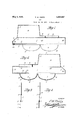
- FIG. 1 is an inside plan view of the cap, inits fiat position, before being folded into cap formation.
- Fig. 2 is an outside elevation of the cap, in itsfiat position, before being folded into cap formation.
- Fig.3 is a sectional View, taken on line -33 of Fig. 2.
- Fig. 4 is a sectional view taken on line 4-4 of Fig. 2.
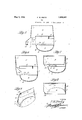
- Fig. 5 is-a side-view of the cap with the head band thereof folded upon itself approximately midway its length.
- Fig. 6 is a side View of the cap, similar to Fig. 5 with one end of the head band folded over for hook connection with the pleated tape carried thereby.
- Fig. 7 is a side view of the cap, similar to Fig. 6 and showing the crown section thereof folded over into engagement with the head. band.
- Fig. 8 is a side view of the cap,- similar to Fig. 7, but with the side flaps folded upwardly and a part of the crown section of the cap interposed between one of the flaps and the head band.
- Fig. 9 is a perspective view of the cap, as folded, the view being taken from the front and one side.
- I employ a normally flat head band 1 made from duck, or any other suitable fabric, the rear upper corner of which is preferably cut away, as at 2,.
- the upper and end edges of the head band 1 are provided with suitable thread stitchings 8, or similarly worked to conceal the raw edges thereof.
- the lower edge of theheadband 1 is preferably hemmed as at 4 and covered with a suitable tape strip 5 which is stitched, as at 6, tothe hemmed edge of the head bandvand adapted to act as i a sweat band.
- Suitable. flat fabric flaps designated 7 and 8 are secured at suitable locations to the lower hemmed edge of the-head band 1 bythe lower row of stitchings 6 and between the head band 1 and the tape strip 5.
- Thefree edges of the flaps 7 and 8 are h mmed, as at 9 and 10, respectively, or otherwise worked, to conceal the raw edges of the flaps, which edges are preferably curved, as at 11 and 12, respectively.
- the free edges ofthe crown section 13 and its end extension 1 1 is provided with suitable thread stitchings 17 or similarly worked to conceal the raw edges thereof.
- the crown section 13 extends from one end of the upper edge of the head band 1, that is from the cut off corner thereof, to a point approximately midway the ends of the head band 1, and the end extension 14 thereof extends a short distance beyond the point midway the ends of the head band 1, as shown in Figs. 1 and 2, to provide a. crown supporting strip.
- the free edges of the crown supporting strip 18 are provided with suitable thread stitchings 21, or equivalently worked, to conceal the raw edges thereof.
- the head band 1 extends beyond the one I end of the crown supporting strip 18 and one end of the flap 8 to provide a head band lap, or extension 22.
- the opposite end of the head band 1 having the cut off corner 2 extends beyond the one end of the crown sec tion 13 to provide a head band lap, or extension 23, both of which extensions are adapted to overlap each other when the material is folded for use as a cap.
- the overlapped ends of the head band are at the rear of the cap and the overlap varies in length, dependent upon the adjustment of the head cap size, as will be apparent hereinafter.
- the lower edge of the outside face of the head band 1, nearest the head band extension 22, as shown in Fig. 2, is provided with a suit able length of tape 24, which is transversely pleated along its length, as at 25, to provide a plurality of engaging means for a book 26,
- the hook 26 may be brought into engagement with any selected plea-t 25 to form a cap of any desired head size.
- the head band size of the cap can be varied, as it is adjustable.
- the cap is folded from its flat condition, as clearly illustrated in Figs. 5, 6, 7 and 8, which folding operations are as follows:
- the cap material is first laid out flat, as
- the head band which makes the first formation of the cap appear, as shown in Fig. 5.
- the head band extension 23 and part of one edge portion of the crown 13 is folded over, as shown in Fig. 6 and the hook 26 is then hooked into aselected tape pleat 25 to give the. cap the desired head size, as ismanifest.
- the crown portion 13 is folded over that part of the head band to which the pleated hook engaging tape is secured.
- the flaps 7 and 8 are folded upwardly to lie against the sides of the cap, as shown in Figs. 8 and 9. As shown, the flap 7 is disposed alongside that part of the head band to which the crown has been secured and the other flap 8 lies alongside a portion of the folded over crown, so that a portion of the crown lies between the flap 8 and that part of the head band carrying the hook engaging pleated tape.
- the cap can be properly ventilated through the upper front and rear corners thereof, due to an opening 28 being provided by the folding over of the crown piece 13, as clearly shown in Fig. 9.
- the crown is not stitched to other parts of the cap excepting along one edge thereof, it is obvious that when folded into position, the end of the crown, where folded, provides the necessary ventilating openings.
- the invention in its preferred form as being made up of ahead band section to which is secured separate crown section, a separate crown supporting strip and two independent side flaps, it is obvious that the headband, crown, crown support and the side flaps may be, if desired, cut as a unit from a single piece of suitable cap forming fabric.
- a head band a flap crown section seamed along its inner edge to a part of the upper edge of the head hand, a crown supporting strip seamed along its inner edge to the upper edge of the head band adjacent one end of the crown section, a pair of side flaps stitched along their inner edges to the lower edge of the head band and adapted to be turned up against the head band to conceal the head hand, a pleated strip stitched to the outer face of the head band near one end thereof and adjacent one of the side flaps and a hook secured to the inner face of the head band opposite the end carrying the pleated strip and adapted for engagement with a selected pleat.
- a cap for waiters and the like made from flexible fabric comprising, in combination, a single elongated headband section having a straight upper and lower edge and having one of its upper corners cut away, a substantially rectangular foldable crown section extending from approximately half of the upper edge of the head band section, a crown supporting strip formed along the upper edge of the head band section adjacent one end of the crown section, means for connecting the head band when folded to fit the wearers head and a pair of flaps formed along the lower edge of the head band section adapted to be folded upwardly with one of the flaps in close engagement with the head hand on one side of the wearers head and the other flap in close engagement with both the head band and the free longitudinal edge of the crown section on the opposite side of the wearers head.
Landscapes
- Details Of Garments (AREA)
Description
F. w. PEETZ' May 3, 1932.
CAP
Filed Nov. 29, 1930 2 ShQQ'bS-ShSQt INVENTOR.
A TTORNE Y.
F. w. PEETZ May 3, .1932.
CAP
2 Sheetsfiheet 2 Filed Nov. 29,. 1950 INVENTOR. [Vi P6653, BY
- ATTORNEY.
Patented May 3, 1932 PATENT OFFICE FREDERICK W. IPEETZ, 0F WEBSTER GROVES, MISSOURI CAP Applicationv filed November 29, 1930. Serial 110. 499,629.
My invention relates to fabric caps, such as worn by soda dispensers, cooks, waiters and others where the use of fabric caps is required.
The object of my present invention is the provision of a cap, which can be washed and ironed in a flat condition.
A further object of the invention is the pro vision of a cap so constructed that it can be readily folded by the wearer thereof to resemble a cap of the overseas design.
A still further object of the invention is to provide the cap with a pleated strip of tape and a hookfor engaging a selected pleat so that the cap can be adjusted to any desired head size.
A further object of the invention resides in the provision of a folded fabric cap, which due to openings being formed at the upper front and rear corners thereof by the folding over of the crown piece, permits the cap to be properly Ventilated.
A still further object of the invention is the provision of a cap which possesses advantages in points of simplicity and efficiency, and, at the same time proves itself comparatively inexpensive in cost of manufacture.
With the above and other objects in view, the invention consists in the novel features of construction, arrangement and combination of parts hereinafter more fully described and finally pointed out in the claims hereto appended.
Referring to the accompanying drawmgs forming a part of this specification, wherein like characters of reference denote similar parts throughout the several views ,Fig. 1 is an inside plan view of the cap, inits fiat position, before being folded into cap formation.
Fig. 2is an outside elevation of the cap, in itsfiat position, before being folded into cap formation.
Fig.3 is a sectional View, taken on line -33 of Fig. 2.
Fig. 4 is a sectional view taken on line 4-4 of Fig. 2.
Fig. 5 is-a side-view of the cap with the head band thereof folded upon itself approximately midway its length.
Fig. 6 is a side View of the cap, similar to Fig. 5 with one end of the head band folded over for hook connection with the pleated tape carried thereby.
Fig. 7 is a side view of the cap, similar to Fig. 6 and showing the crown section thereof folded over into engagement with the head. band.
Fig. 8 is a side view of the cap,- similar to Fig. 7, but with the side flaps folded upwardly and a part of the crown section of the cap interposed between one of the flaps and the head band. A
Fig. 9 is a perspective view of the cap, as folded, the view being taken from the front and one side.
In carrying out the aim of my invention, I employ a normally flat head band 1 made from duck, or any other suitable fabric, the rear upper corner of which is preferably cut away, as at 2,. The upper and end edges of the head band 1 are provided with suitable thread stitchings 8, or similarly worked to conceal the raw edges thereof. The lower edge of theheadband 1 is preferably hemmed as at 4 and covered with a suitable tape strip 5 which is stitched, as at 6, tothe hemmed edge of the head bandvand adapted to act as i a sweat band.
Suitable. flat fabric flaps designated 7 and 8, preferably, although not necessarily, of the same material as the head band 1, are secured at suitable locations to the lower hemmed edge of the-head band 1 bythe lower row of stitchings 6 and between the head band 1 and the tape strip 5. Thefree edges of the flaps 7 and 8 are h mmed, as at 9 and 10, respectively, or otherwise worked, to conceal the raw edges of the flaps, which edges are preferably curved, as at 11 and 12, respectively.
A normally fiat-crown section 13 having an end extension 1 1 of reduced width, preferably, although not necessarily of the same material as the head band 1, is hemmed along one of its edges, as at 15, and secured to the upper edge of the head band by means of the stitchings 16. The free edges ofthe crown section 13 and its end extension 1 1 is provided with suitable thread stitchings 17 or similarly worked to conceal the raw edges thereof.
The crown section 13 extends from one end of the upper edge of the head band 1, that is from the cut off corner thereof, to a point approximately midway the ends of the head band 1, and the end extension 14 thereof extends a short distance beyond the point midway the ends of the head band 1, as shown in Figs. 1 and 2, to provide a. crown supporting strip.
An additional crown supporting strip 18, preferably of the same width as the crown extension 1 1, and although not necessarily of the same material as the head band 1, is hemmed along its lower edge, as at 19 and secured to the upper edge of the head band 1 adjacent the free end edge of the crown extension 14 by means of the stitchings 16, which are a continuation of the stitchings 20. The free edges of the crown supporting strip 18 are provided with suitable thread stitchings 21, or equivalently worked, to conceal the raw edges thereof.
The head band 1 extends beyond the one I end of the crown supporting strip 18 and one end of the flap 8 to provide a head band lap, or extension 22. The opposite end of the head band 1 having the cut off corner 2, extends beyond the one end of the crown sec tion 13 to provide a head band lap, or extension 23, both of which extensions are adapted to overlap each other when the material is folded for use as a cap. The overlapped ends of the head band are at the rear of the cap and the overlap varies in length, dependent upon the adjustment of the head cap size, as will be apparent hereinafter.
The lower edge of the outside face of the head band 1, nearest the head band extension 22, as shown in Fig. 2, is provided with a suit able length of tape 24, which is transversely pleated along its length, as at 25, to provide a plurality of engaging means for a book 26,
which hook is suitably secured upon the head band tape 5 near the lower corner of the head band extension 23. By this arrangement, the hook 26 may be brought into engagement with any selected plea-t 25 to form a cap of any desired head size. the head band size of the cap can be varied, as it is adjustable.
The cap is folded from its flat condition, as clearly illustrated in Figs. 5, 6, 7 and 8, which folding operations are as follows:
The cap material is first laid out flat, as
- shown in Fig. 1 with the side of the material having the pleated hook engaging strip laid to the bottom. The right half of the head band 1, as shown in Fig. 1, is then folded over upon the other half of the head band along the line designated 27 and the end extension 22 is folded under the folded part of Thus, it will be seen that the head band, which makes the first formation of the cap appear, as shown in Fig. 5. After the flat cap material has been folded, as shown in Fig. 5, the. head band extension 23 and part of one edge portion of the crown 13 is folded over, as shown in Fig. 6 and the hook 26 is then hooked into aselected tape pleat 25 to give the. cap the desired head size, as ismanifest. After the cap material has been folded into cap formation, as shown in Fig. 6, the crown portion 13 is folded over that part of the head band to which the pleated hook engaging tape is secured.
Finally, after the material has been folded in the cap formation shown in Fig. 7, the flaps 7 and 8 are folded upwardly to lie against the sides of the cap, as shown in Figs. 8 and 9. As shown, the flap 7 is disposed alongside that part of the head band to which the crown has been secured and the other flap 8 lies alongside a portion of the folded over crown, so that a portion of the crown lies between the flap 8 and that part of the head band carrying the hook engaging pleated tape.
It will be understood that the cap can be properly ventilated through the upper front and rear corners thereof, due to an opening 28 being provided by the folding over of the crown piece 13, as clearly shown in Fig. 9. As the crown is not stitched to other parts of the cap excepting along one edge thereof, it is obvious that when folded into position, the end of the crown, where folded, provides the necessary ventilating openings.
From the foregoing description, it is evident that I provide a fabric cap structure which is normally flat in shape, to enable the cap to be washed and ironed in a flat condition,
. to facilitate the manufacture of the cap, as
only one size is required to be made and yet provide a cap which will fit various sizes of heads due to the use of a hook and hook engaging pleats, as-hereinbefore described.
WhileI have shown and described the invention in its preferred form as being made up of ahead band section to which is secured separate crown section, a separate crown supporting strip and two independent side flaps, it is obvious that the headband, crown, crown support and the side flaps may be, if desired, cut as a unit from a single piece of suitable cap forming fabric.
The many advantages of the herein described invention will readily suggest themselves to those skilled in the art to which it appertains.
' From the foregoing description, it is evident that a simple device for this purpose has been disclosed, but it is to be understood that I do not desire to restrict, or limit myself to the very details of the construction shown and described, which is merely illustrative, it being obvious that changes, not involving the 7 exercise of invention, may be made without conflicting or departing from the spirit of the invention within the scope of the appended claims.
What I claim is:
1. In a cap of the class described, a head band, a flap crown section seamed along its inner edge to a part of the upper edge of the head hand, a crown supporting strip seamed along its inner edge to the upper edge of the head band adjacent one end of the crown section, a pair of side flaps stitched along their inner edges to the lower edge of the head band and adapted to be turned up against the head band to conceal the head hand, a pleated strip stitched to the outer face of the head band near one end thereof and adjacent one of the side flaps and a hook secured to the inner face of the head band opposite the end carrying the pleated strip and adapted for engagement with a selected pleat.
2. A cap for waiters and the like made from flexible fabric comprising, in combination, a single elongated headband section having a straight upper and lower edge and having one of its upper corners cut away, a substantially rectangular foldable crown section extending from approximately half of the upper edge of the head band section, a crown supporting strip formed along the upper edge of the head band section adjacent one end of the crown section, means for connecting the head band when folded to fit the wearers head and a pair of flaps formed along the lower edge of the head band section adapted to be folded upwardly with one of the flaps in close engagement with the head hand on one side of the wearers head and the other flap in close engagement with both the head band and the free longitudinal edge of the crown section on the opposite side of the wearers head.
In testimony whereof, I have hereunto affixed my signature.
4 FREDERICK W. PEETZ.
Priority Applications (1)
| Application Number | Priority Date | Filing Date | Title |
|---|---|---|---|
| US499029A US1856967A (en) | 1930-11-29 | 1930-11-29 | Cap |
Applications Claiming Priority (1)
| Application Number | Priority Date | Filing Date | Title |
|---|---|---|---|
| US499029A US1856967A (en) | 1930-11-29 | 1930-11-29 | Cap |
Publications (1)
| Publication Number | Publication Date |
|---|---|
| US1856967A true US1856967A (en) | 1932-05-03 |
Family
ID=23983510
Family Applications (1)
| Application Number | Title | Priority Date | Filing Date |
|---|---|---|---|
| US499029A Expired - Lifetime US1856967A (en) | 1930-11-29 | 1930-11-29 | Cap |
Country Status (1)
| Country | Link |
|---|---|
| US (1) | US1856967A (en) |
Cited By (2)
| Publication number | Priority date | Publication date | Assignee | Title |
|---|---|---|---|---|
| US2856608A (en) * | 1956-06-11 | 1958-10-21 | Gilbert B Wagenfeld | Adjustable headpiece |
| FR2553633A1 (en) * | 1983-10-25 | 1985-04-26 | Harmand Jean | Device for producing disposable caps, intended for the food, medical and building professions, which can be adjusted to size and delivered flat |
-
1930
- 1930-11-29 US US499029A patent/US1856967A/en not_active Expired - Lifetime
Cited By (2)
| Publication number | Priority date | Publication date | Assignee | Title |
|---|---|---|---|---|
| US2856608A (en) * | 1956-06-11 | 1958-10-21 | Gilbert B Wagenfeld | Adjustable headpiece |
| FR2553633A1 (en) * | 1983-10-25 | 1985-04-26 | Harmand Jean | Device for producing disposable caps, intended for the food, medical and building professions, which can be adjusted to size and delivered flat |
Similar Documents
| Publication | Publication Date | Title |
|---|---|---|
| US3555565A (en) | Nurse's surgical cap | |
| US2245779A (en) | Cover for couches and the like | |
| US2227180A (en) | Reversible automobile seat cover | |
| US3229308A (en) | Head band and an improved fabric jointure | |
| US3213466A (en) | Turban-type cap | |
| US3084346A (en) | Infant's drying garment | |
| US2055560A (en) | Muffler | |
| US2051084A (en) | Adjustable cap | |
| US1780887A (en) | Marcel cap | |
| US1856967A (en) | Cap | |
| US2673350A (en) | Convertible bonnet | |
| US1748890A (en) | Garment | |
| US3187346A (en) | Adjustable garment closure | |
| US5669076A (en) | Adjustable size selectable pie hat | |
| US2343758A (en) | Skull fitting hat | |
| US1600530A (en) | Helmet hair cap | |
| US2396503A (en) | Hat | |
| US2990552A (en) | Discardable cap construction | |
| US1073345A (en) | Automobile-bonnet. | |
| US1651929A (en) | Adjustable cap | |
| US4068319A (en) | Chef's hat | |
| US2624884A (en) | Headdress | |
| US3512180A (en) | Cap | |
| US1629188A (en) | Knitted cap | |
| US2158861A (en) | Visor for collapsible caps |