US1856868A - Seat side arm cover - Google Patents
Seat side arm cover Download PDFInfo
- Publication number
- US1856868A US1856868A US318647A US31864728A US1856868A US 1856868 A US1856868 A US 1856868A US 318647 A US318647 A US 318647A US 31864728 A US31864728 A US 31864728A US 1856868 A US1856868 A US 1856868A
- Authority
- US
- United States
- Prior art keywords
- side arm
- cover
- car
- arm
- reinforcing
- Prior art date
- Legal status (The legal status is an assumption and is not a legal conclusion. Google has not performed a legal analysis and makes no representation as to the accuracy of the status listed.)
- Expired - Lifetime
Links
- 230000003014 reinforcing effect Effects 0.000 description 10
- 230000002787 reinforcement Effects 0.000 description 5
- 239000004744 fabric Substances 0.000 description 1
- 238000007493 shaping process Methods 0.000 description 1
Images
Classifications
-
- A—HUMAN NECESSITIES
- A47—FURNITURE; DOMESTIC ARTICLES OR APPLIANCES; COFFEE MILLS; SPICE MILLS; SUCTION CLEANERS IN GENERAL
- A47C—CHAIRS; SOFAS; BEDS
- A47C7/00—Parts, details, or accessories of chairs or stools
- A47C7/54—Supports for the arms
Definitions
- My invention relates to improvements in removable or so-called slip covers for the side arms of seats, and particularly for the side arms of car seats. As is well known, it
- the object of my invention is to produce a side arm cover which can easily be adapted to various forms'of side arms and, as stated, especially for the side arms of motor car seats, and also'to providemeans for firmly, but detachably, securing the cover in place.
- Fig. 1 is a general front view ofa car seat with the side arm in section and my improved cover applied;
- Fig. 2 is an enlarged cross section of the side arm with the cover slightly removed and in position to be applied;
- Fig. 3 is a view similar to Fig. 2 but with the cover in position;
- Fig. 4. is an inside elevation of the side arm and cover with the latter applied;
- Fig. 5 is a cross section through the side arm showing a slightly modified type of cover adapted to a different shape of side arm;
- Fig. 6 is a view similar to Fig. 5 but showing the cover partly removed;
- Fig. 7 is a cross section of another form of side arm and correspondingly 'modified cover with the cover removed;
- Fig. 8 is a view similar to Fig. 7 but with the cover for the side arm applied;
- Fig. 9 is a vertical longitudinal section through the side arm with parts of the cover portion broken away.
- Fig. 10 is a detail of the reinforcing strip iorming a part of the structure shown in ig. 9. v
- the car seat 10 may beof any usual character and it is illustrated in connection with the adjacent side 11 of the car, and with a rather conventional side arm 12.
- the latter has a. rigid core 13 upon which the upholstering 14 is placed and both the core and the upholstering vary with diiferent makes of cars and with different designs of the same make. Quite frequently, however, these side arms have a little space 15 between the upper part of the upholstery and the adjacent side of the car. This is rather exaggerated in the drawings and in the actual car it usually appears and is not much more than a crack but it exists and a reinforcing and fastening means can be wedged or pushed down into this space because the upholstery will give sufficiently to permit it.
- the cover 16 of any suitable fabric is adapted to envelope the exposed part of the side arm and with the type of side arm shown 80 in the figures referred to it is provided with a reinforced upper edge adapted to be pushed into the space 15.
- Such reinforcement can be, most conveniently, a hem 17 with a stifiening rod or member 18 therein.
- this s'tifi'ening element can be otherwise associated with the upper edge of the cover and it can be any stiffening means'which will permit the said edge to be forced into the space 15.
- the upper, lower and front corners of the side arm cover are preferably reinforced or stifiened in some manner to prevent wear and to better define the shape of the cover so that it will stay in place better and make the corners more durable, as these are the most exposed.
- This corner reinforcement might be a binding, or it can conveniently be secured by making a hem 19 at the exposed parts, which is shown in Fig. 4, extend entirely around the side arm, but if one part or inner end of the side arm would be of such a character to prevent such reinforcement, it will of course be absent.
- the side arm. illustrated in Figs. 1% isessentially rectangular in cross section and therefore the cover on the under side of the side arm is pushed upsnugly in place and secured by a clamping member 20 which can be a rod of the contourof the under side of the side arm and the clamping member can be secured in any convenient way.
- Figs. 5 and 6 a slightly different form of side arm is used in which the core or rigid part 13 tapers downwardly on the under side and of course the arm as a whole is correspondingly shaped.
- the clamping member 20 can be d spensed with and in the figures referred to I have shown the cover left smooth at the corners without the reinforcing 19 above described.
- the bar or clamping member 20 can be omitted and the cover will rather closely follow the curve of the under side of the arm.
- the cover 16 illustrated in these figures hasthe same reinforcement at its upper'edge and its lower edge can be doubled over as at 23 if desired, or can be left without reinforcement and is secured by a fastening means 24 beneath the seat cushion 25.
- Figs; 7 to 10 I have shown another type of side arm and with the cover correspondingly modified to meet the conditions of such a change.
- the side arm has no space left between the upper part of the upholstery and the side of the car 11, consequently the cover 16 has to be correspondingly modified, but as in the other cases, it has reinforcing and securing means at its inner edge.
- a hem 26 extends around the top front and down the sides of the cover at its inner edge and in itis placed astiffening element 27 which can be, conveniently, a metallic strap or strip, and-which is shaped to thecontourof the arm". It is illustrated as having holes 29"through whichithe' screws 28 may pass to fasten it, and the cover connected therewith, in position.
- the cover 16" in this instance is shown as fitting snugly upon the side arm and this type of cover has preferably the reinforced corner part 19.
- my invention comprises a cover which will fit smoothly upon a side arm so as to cover all exposed parts, that it has reinforcing and securing means at the parts adjacent the outer edge of the side arm, and that the details ofsupporting and fastening the cover must, of necessity, vary with the different types and sizes of side arms, but the principle which I have illustrated is easily applicable to these various arms.
- a slip cover for the side arm of a car seat shaped to envelope the side arm, having a stiffened upper edge fitting snugly between the arm and car wallto bind the cover at said parts, and reinforcing and shaping parts disposed to come opposite the exposed corners of the side arm.
- a slip cover for the side arm'of a'motor car seat shaped to envelope the side arm, and having reinforcing and-detachable securing means at points adapted to come at the junction of the upper and lower parts of the side arm with theadjacent carside and to substantially follow the contour of saidjunction parts, said upper securing means comprising a stiffened cover edge shaped to be pushed between the side arm andcar wall and be thereby bound.
- a slip cover for the side arm of a car seat shaped to envelope the said side arm, havlng a stiffened upper edge to fit and be frictionally bound between the side arm and a partof the car, and a separate clamping member to secure the under part of the cover to the'side arm.
- g g 4 A slip cover for the side arm of a car seat, shaped to envelope the said side arm, and stiffening and reinforcing meansassociated with the upper and under side of'th'e cover-adjacent thejunction with the side of the car and adapted to detachably secure the cover in position on the side arm, said upper securing means comprising a stiffened cover edge adapted to lit and befrictionally bound betweenthe side arm and the car wall.
- a slip cover for the side arm of a car seat shaped to envelope the side arm having a stiffened upper edge shaped to fit and be frictionally bound between the side arm and a part of thecar, and means for fastening the cover below the side arm and near the junction of the side arm and .the adjacent part of the car.
Landscapes
- Seats For Vehicles (AREA)
Description
May 3, 1932. w. L. FRY
SEAT SIDE ARM COVER '5 Sheets-Sheet 1 Filed Nov. 12, 1928 wirxapwnrwf May 3, 1932. w 1 1 85'6,868
SEAT SIDE ARM COVER Filed Nov. 12, 1928 a sheets-sh e t 2 May 3,1932. w FRY 1,856,868
SEAT SIDE ARM COVER Filed Nov. 12, 1928 I5 Sheets-Sheet 3' A Mm.
Patented May 3, 1932 UNITED STATES WALTER I1. FRY, OF SCARSDALE, NEW YORK, ASSIGNOR, BY MESNE ASSIGNMENTS, TO WIL-IERY CORPORATION, OF NEW YORK, N. Y., A CORPORATION OF DELAWARE SEAT SIDE ARM COVER My invention relates to improvements in removable or so-called slip covers for the side arms of seats, and particularly for the side arms of car seats. As is well known, it
isa general practice to provide slip covers for car seats and to make the cover for a side arm so that it can be easily applied or removed and will fit nicely thereon is very difficult. It is important that the side arm be covered because it is subject to a good deal of wear and because of its prominence it is desirable that the cover may be handsome and lie smoothly.
The object of my invention is to produce a side arm cover which can easily be adapted to various forms'of side arms and, as stated, especially for the side arms of motor car seats, and also'to providemeans for firmly, but detachably, securing the cover in place.
It will be understood that while I have shown and described a cover suitable for the side arms illustrated in the accompanying drawings the invention includes manyvariations in shape because the side arms of yarious cars and seats difier greatly in design.
Further objects and advantages will appear from the following description and drawings in which similar reference characters refer to similar parts throughout the various views.
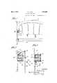
Fig. 1 is a general front view ofa car seat with the side arm in section and my improved cover applied;
Fig. 2 is an enlarged cross section of the side arm with the cover slightly removed and in position to be applied;
Fig. 3 is a view similar to Fig. 2 but with the cover in position;
Fig. 4. is an inside elevation of the side arm and cover with the latter applied;
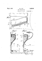
Fig. 5 is a cross section through the side arm showing a slightly modified type of cover adapted to a different shape of side arm;
Fig. 6 is a view similar to Fig. 5 but showing the cover partly removed;
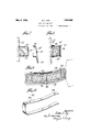
Fig. 7 is a cross section of another form of side arm and correspondingly 'modified cover with the cover removed;
Fig. 8 is a view similar to Fig. 7 but with the cover for the side arm applied;
. Fig. 9 is a vertical longitudinal section through the side arm with parts of the cover portion broken away; and
Fig. 10 is a detail of the reinforcing strip iorming a part of the structure shown in ig. 9. v
As illustrated in Figs. 1 to 4, the car seat 10 may beof any usual character and it is illustrated in connection with the adjacent side 11 of the car, and with a rather conventional side arm 12.
The latter has a. rigid core 13 upon which the upholstering 14 is placed and both the core and the upholstering vary with diiferent makes of cars and with different designs of the same make. Quite frequently, however, these side arms have a little space 15 between the upper part of the upholstery and the adjacent side of the car. This is rather exaggerated in the drawings and in the actual car it usually appears and is not much more than a crack but it exists and a reinforcing and fastening means can be wedged or pushed down into this space because the upholstery will give sufficiently to permit it.
The cover 16 of any suitable fabric is adapted to envelope the exposed part of the side arm and with the type of side arm shown 80 in the figures referred to it is provided with a reinforced upper edge adapted to be pushed into the space 15. Such reinforcement can be, most conveniently, a hem 17 with a stifiening rod or member 18 therein. Obviously this s'tifi'ening element can be otherwise associated with the upper edge of the cover and it can be any stiffening means'which will permit the said edge to be forced into the space 15.
The upper, lower and front corners of the side arm cover are preferably reinforced or stifiened in some manner to prevent wear and to better define the shape of the cover so that it will stay in place better and make the corners more durable, as these are the most exposed.
This corner reinforcement might be a binding, or it can conveniently be secured by making a hem 19 at the exposed parts, which is shown in Fig. 4, extend entirely around the side arm, but if one part or inner end of the side arm would be of such a character to prevent such reinforcement, it will of course be absent. The side arm. illustrated in Figs. 1% isessentially rectangular in cross section and therefore the cover on the under side of the side arm is pushed upsnugly in place and secured by a clamping member 20 which can be a rod of the contourof the under side of the side arm and the clamping member can be secured in any convenient way. A good way is illustrated in which the member is pierced with holes 21 through which extend fastening elements 22 which engage into the adjacent side of the car, or other support which may be present at this point. The lower part of the cover extends downward and can be secured in any way, as for example the way presently described and illustrated in Figs. 5 and 6.
In Figs. 5 and 6 a slightly different form of side arm is used in which the core or rigid part 13 tapers downwardly on the under side and of course the arm as a whole is correspondingly shaped. In this case the clamping member 20 can be d spensed with and in the figures referred to I have shown the cover left smooth at the corners without the reinforcing 19 above described. In a structure of this shape the bar or clamping member 20 can be omitted and the cover will rather closely follow the curve of the under side of the arm.
The cover 16 illustrated in these figures hasthe same reinforcement at its upper'edge and its lower edge can be doubled over as at 23 if desired, or can be left without reinforcement and is secured by a fastening means 24 beneath the seat cushion 25.
In Figs; 7 to 10 I have shown another type of side arm and with the cover correspondingly modified to meet the conditions of such a change. Here the side arm has no space left between the upper part of the upholstery and the side of the car 11, consequently the cover 16 has to be correspondingly modified, but as in the other cases, it has reinforcing and securing means at its inner edge. AS here illustrated, a hem 26 extends around the top front and down the sides of the cover at its inner edge and in itis placed astiffening element 27 which can be, conveniently, a metallic strap or strip, and-which is shaped to thecontourof the arm". It is illustrated as having holes 29"through whichithe' screws 28 may pass to fasten it, and the cover connected therewith, in position. The cover 16" in this instance is shown as fitting snugly upon the side arm and this type of cover has preferably the reinforced corner part 19.
The several illustrations which I have made show that my invention comprises a cover which will fit smoothly upon a side arm so as to cover all exposed parts, that it has reinforcing and securing means at the parts adjacent the outer edge of the side arm, and that the details ofsupporting and fastening the cover must, of necessity, vary with the different types and sizes of side arms, but the principle which I have illustrated is easily applicable to these various arms.
What I claim is:
1. A slip cover for the side arm of a car seat, shaped to envelope the side arm, having a stiffened upper edge fitting snugly between the arm and car wallto bind the cover at said parts, and reinforcing and shaping parts disposed to come opposite the exposed corners of the side arm.
2. A slip cover for the side arm'of a'motor car seat, shaped to envelope the side arm, and having reinforcing and-detachable securing means at points adapted to come at the junction of the upper and lower parts of the side arm with theadjacent carside and to substantially follow the contour of saidjunction parts, said upper securing means comprising a stiffened cover edge shaped to be pushed between the side arm andcar wall and be thereby bound.
3. A slip cover for the side arm of a car seat, shaped to envelope the said side arm, havlng a stiffened upper edge to fit and be frictionally bound between the side arm and a partof the car, and a separate clamping member to secure the under part of the cover to the'side arm. g g 4. A slip cover for the side arm of a car seat, shaped to envelope the said side arm, and stiffening and reinforcing meansassociated with the upper and under side of'th'e cover-adjacent thejunction with the side of the car and adapted to detachably secure the cover in position on the side arm, said upper securing means comprising a stiffened cover edge adapted to lit and befrictionally bound betweenthe side arm and the car wall.
5. A slip cover for the side arm of a car seat shaped to envelope the side arm having a stiffened upper edge shaped to fit and be frictionally bound between the side arm and a part of thecar, and means for fastening the cover below the side arm and near the junction of the side arm and .the adjacent part of the car.
6. A slip cover forthe side arm of a car seat shapedto envelope the side arm having reinforcing and securing means to attach it to the sidefarmon theupper 'andilowe'r parts of said arm and near the junction of the a-rniand the adjacent well, said upper means comprising a stiffening element at the cover edge frictionally held between the side arm and car wall, said cover havin reinforcing parts following the contour o the arm and disposed to lie opposite the greatest wearing parts of the side arm.
In testimony whereof, I have signed my name to this specification this 31st day of October, 1928.
WALTER L. FRY.
Priority Applications (1)
| Application Number | Priority Date | Filing Date | Title |
|---|---|---|---|
| US318647A US1856868A (en) | 1928-11-12 | 1928-11-12 | Seat side arm cover |
Applications Claiming Priority (1)
| Application Number | Priority Date | Filing Date | Title |
|---|---|---|---|
| US318647A US1856868A (en) | 1928-11-12 | 1928-11-12 | Seat side arm cover |
Publications (1)
| Publication Number | Publication Date |
|---|---|
| US1856868A true US1856868A (en) | 1932-05-03 |
Family
ID=23239026
Family Applications (1)
| Application Number | Title | Priority Date | Filing Date |
|---|---|---|---|
| US318647A Expired - Lifetime US1856868A (en) | 1928-11-12 | 1928-11-12 | Seat side arm cover |
Country Status (1)
| Country | Link |
|---|---|
| US (1) | US1856868A (en) |
Cited By (5)
| Publication number | Priority date | Publication date | Assignee | Title |
|---|---|---|---|---|
| US2721605A (en) * | 1953-05-18 | 1955-10-25 | David J Griffiths | Arm rest cover |
| US3046573A (en) * | 1960-12-14 | 1962-07-31 | Sr Robert E Davis | Reversible automobile arm rest pillow |
| US3752533A (en) * | 1972-04-05 | 1973-08-14 | E Gilbert | Upholstered seat |
| US5332288A (en) * | 1993-09-16 | 1994-07-26 | Coates John H | Detachable arm cushion for automobile arm rest |
| US7077479B1 (en) | 2004-12-02 | 2006-07-18 | Phillips Glenda J | Vehicular arm rest cover |
-
1928
- 1928-11-12 US US318647A patent/US1856868A/en not_active Expired - Lifetime
Cited By (5)
| Publication number | Priority date | Publication date | Assignee | Title |
|---|---|---|---|---|
| US2721605A (en) * | 1953-05-18 | 1955-10-25 | David J Griffiths | Arm rest cover |
| US3046573A (en) * | 1960-12-14 | 1962-07-31 | Sr Robert E Davis | Reversible automobile arm rest pillow |
| US3752533A (en) * | 1972-04-05 | 1973-08-14 | E Gilbert | Upholstered seat |
| US5332288A (en) * | 1993-09-16 | 1994-07-26 | Coates John H | Detachable arm cushion for automobile arm rest |
| US7077479B1 (en) | 2004-12-02 | 2006-07-18 | Phillips Glenda J | Vehicular arm rest cover |
Similar Documents
| Publication | Publication Date | Title |
|---|---|---|
| US1733007A (en) | Summer top for automobiles | |
| US1856868A (en) | Seat side arm cover | |
| US2123667A (en) | Slip cover | |
| US2005573A (en) | Loose leaf binder | |
| US2143314A (en) | Slip cover for automobile seat cushions | |
| US2071974A (en) | Chair back | |
| US2261651A (en) | Combined casket and grave vault | |
| US2241473A (en) | Chair seat or the like | |
| US2093912A (en) | Cycle saddle | |
| US1906233A (en) | Chair and supporting device | |
| US1862476A (en) | Seat cover | |
| US1621404A (en) | False roof for motor vehicles | |
| US2004982A (en) | Cover for seat side arms | |
| US2314433A (en) | Device for airchutes | |
| US1768383A (en) | Seat-cushion structure | |
| US2304652A (en) | Spring structure | |
| US2230841A (en) | Safety exit fastener | |
| US2312713A (en) | Waste retainer for journal boxes | |
| US1760144A (en) | Rumble-seat inclosure | |
| US2069628A (en) | Overcoat | |
| US1694358A (en) | Radiator-front cover | |
| AT270120B (en) | Seating | |
| US2087964A (en) | Sleeping car construction | |
| USD108888S (en) | Design for a chair | |
| US2334881A (en) | Upholstered door cover |